Roof Design
OBJECTIVE/PURPOSE:
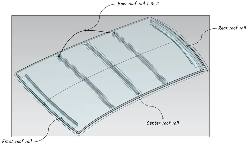
- The main objective of the project is to create the Roof Sheet metal design in NX cad, and also design the Front roof rail, rear roof rail, bow roof front, bow roof rear, and center roof rail, and Reinforcement is creating to build a strong roof.
- To Do a curvature study on the Roof and performance calculations for Heat distortion and Snow load criteria to determine the position of the Bow roofs.
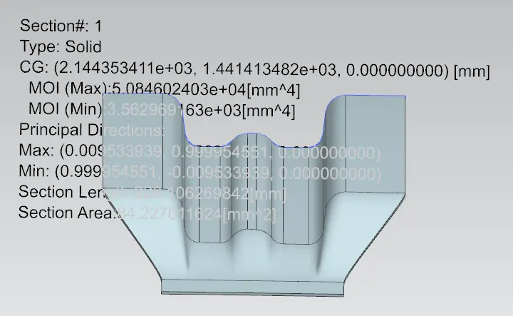
- To Find the moment of inertia and section modulus for Bow-roofs and center roof rail.
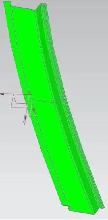
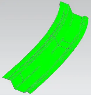
- To Find the Draft Analysis of each part Using NX Cad.
SOFTWARE USED: NX 12.0
- To design the Sheet metal roof in NX by using some Surfacing features.
- NX Cad software is a vastly used automotive, aerospace, and thermal power station. Because it is having modeling, drafting, and manufacturing platform.
Introduction:
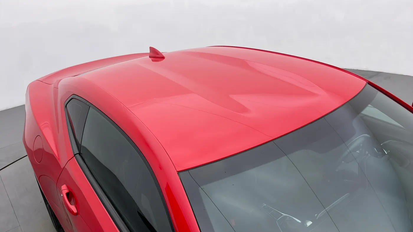
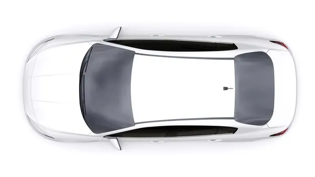
The roof is a crucial component of any vehicle since passengers need a shield to protect them from changing weather conditions.
Passengers prefer cars over other types of vehicles because of the comfort they provide when moving from one location to another.
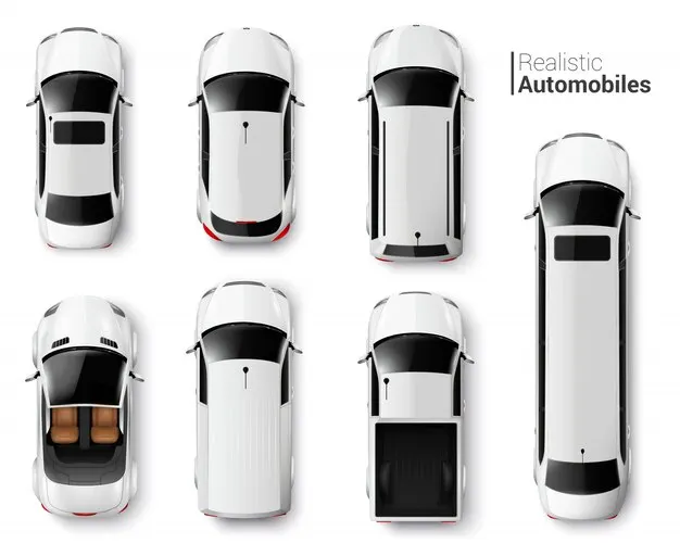
Creating a Roof:
- The roof styling surface obtained from the style team, which takes into account all the design's aesthetic aspects, serves as the
foundation for the roof's structure. - Before beginning the design, the roof design engineer must consider three crucial elements.
They are
- The front visibility standard
- Rear visibility requirements
- Headroom separation
- Curvature study
- Safety parameters
Although they are not load-bearing members, the roofs should be constructed to support loads in order to be
strong and resist permanent deformation in the event of unforeseen circumstances.
Reinforcements for roof:
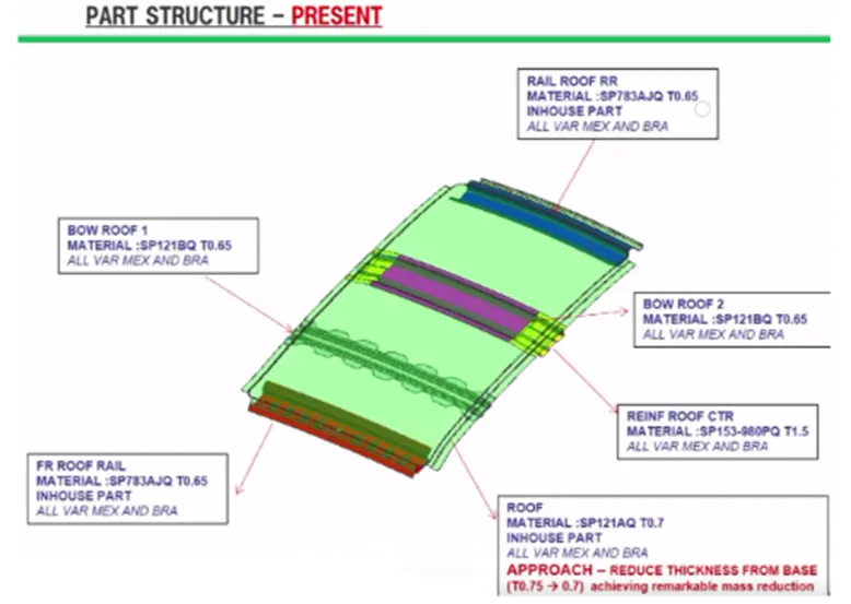
The roofs are reinforced with five structures that act as support members. They are
- Front roof rail
- Rear roof rail
- Center reinforcement roof rail or Center bow roof rail
- Front bow roof rail
- Rear bow roof rail.
Design Consideration:
I believed a simple design would be preferable. I used the procedures below in place of SunRoofs Design.
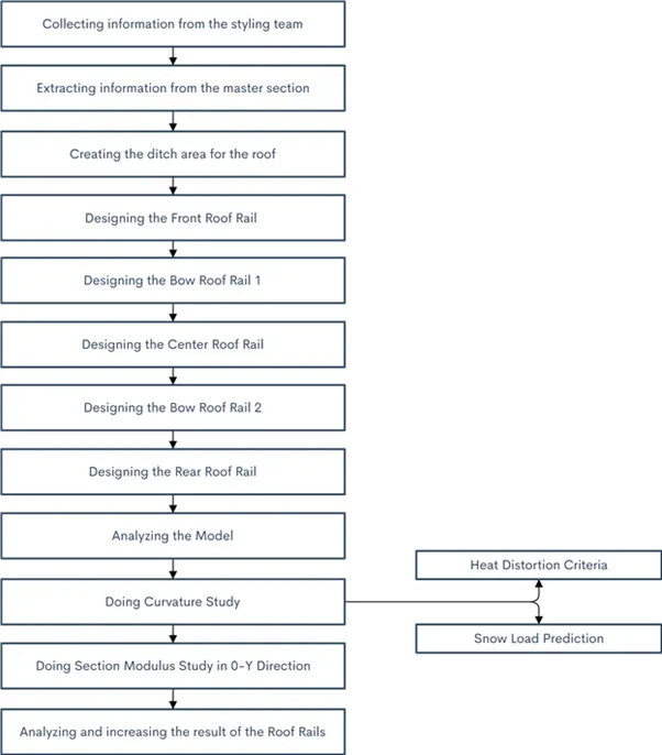
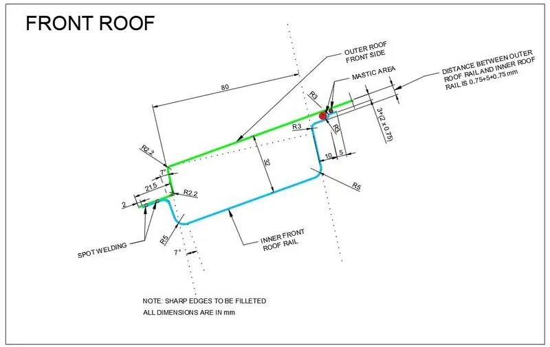
- A draft angle of at least 7 degrees is required.
- The desired height of the bow roof rails added to support the roof surface should not be greater than 20 mm because headroom clearance should be considered.
- The number of bow roof rails and the location of bow roof rails are optimized by taking into consideration empirical formulae like the
- Bow load prediction formula and the Snow load prediction formula.
Reinforcement creation:
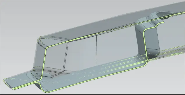
1. Front roof rail:
Input Output
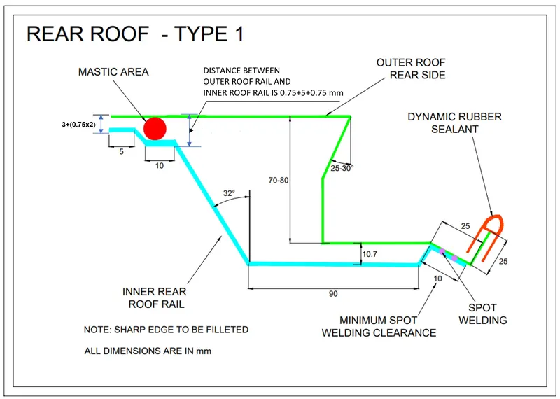
2. Rear roof rail:
Input Output
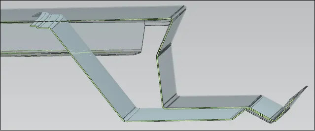
3. Center roof rail:
Input Output
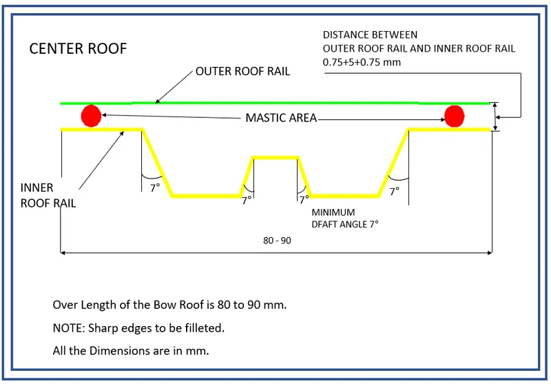
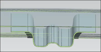
4. Bow roof rail 1&2:
Input Output
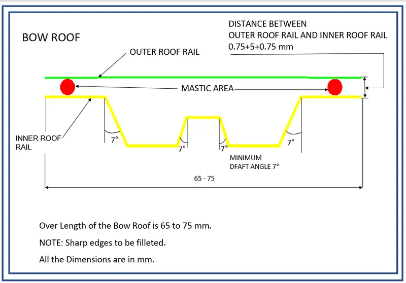

Overview:
Draft Analysis:
1. Front roof rail: 2. Rear roof rail:
3. Center roof rail:

4. Bow roof rail 1&2:

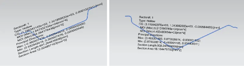
Section modulus:
A geometric characteristic for a specific cross-section that is employed in the design of beams or flexural members is called section modulus. The area for tension and shear, the radius of gyration for compression, the moment of inertia, and the polar moment of inertia for stiffness are further geometric properties employed in the design. Any connection between these attributes depends greatly on the form. Two categories of section moduli exist.
- Elastic section modulus
- Plastic section modulus
The Elastic Section Modulus is defined as, S = I/y
Where,
- S: is the Section Modulus
- I: is the second moment of area(or area moment of inertia, not to be confused with the moment of inertia)
- y: is the distance from the neutral axis to any given fiber. It is often reported using y = c, where c is the distance from the neutral axis to the most extreme fiber
Bow roof rail 1&2: Center roof rail:

Front roof rail: Rear roof rail:
Curvature study/Calculation part:
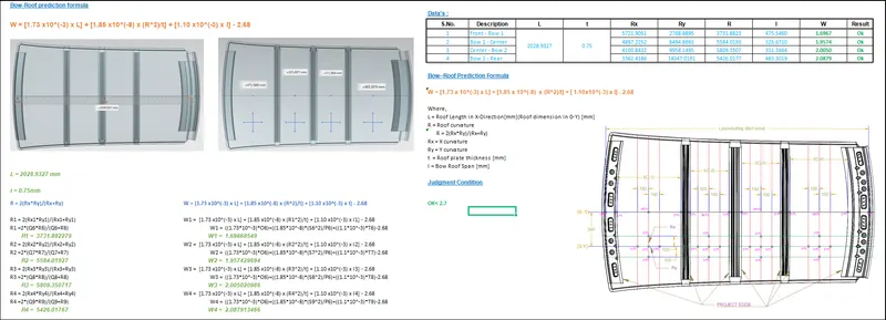
Bow–Roof Prediction Formula
W = [1.73 x 10^(-3) x L] + [1.85 x 10^(-8) x (R^2)/t] + [ 1.10x10^(-3) x l] - 2.68
Where,
L = Roof Length in X-Direction[mm](Roof dimension in 0-Y)
R = Roof curvature
R = 2(Rx*Ry)/(Rx+Ry)
Rx = X curvature
Ry = Y curvature
t = Roof plate thickness [mm]
l = Bow Roof Span [mm]
Judgment Condition
OK< 2.7
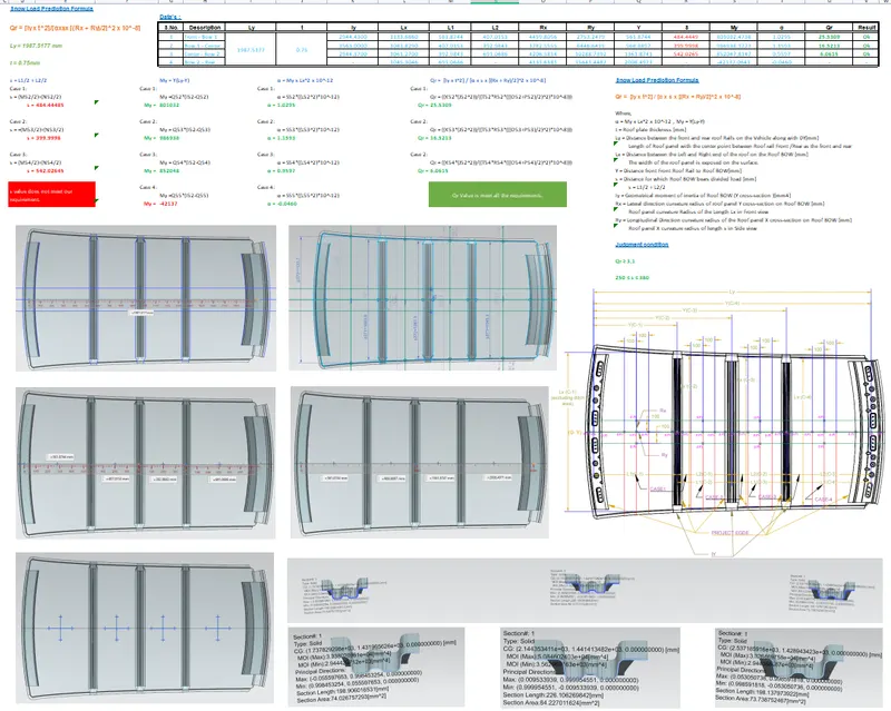
Snow Load Prediction Formula
Qr = [Iy x t2] / [α x s x [(Rx + Ry)/2]2 x 10-8]
Note: The Qr value given over here is correct. There was a typo error in the formula given in the video.
Where,
α = My x Lx2 x 10-12 , My = Y(Ly-Y)
t = Roof plate thickness [mm]
Ly = Distance between the front and rear roof Rails on the Vehicle along with 0Y[mm]
Length of Roof panel with the center point between Roof rail Front /Rear as the front and rear reference point.
Lx = Distance between the Left and Right end of the roof on the Roof BOW [mm]
The width of the roof panel is exposed on the surface.
Y = Distance front Front Roof Rail to Roof BOW[mm]
s = Distance for which Roof BOW bears divided load [mm]
s = L1/2 + L2/2
Iy = Geometrical moment of inertia of Roof BOW (Y cross-section )[mm4]
Rx = Lateral direction curvature radius of roof panel Y cross-section on Roof BOW [mm]
Roof panel curvature Radius of the Length Lx in Front view
Ry = Longitudinal Direction curvature radius of the Roof panel X cross-section on Roof BOW [mm]
Roof panel X curvature radius of length s in Side view
Judgment condition
Qr ≥ 3.1
250 ≤ s ≤ 380
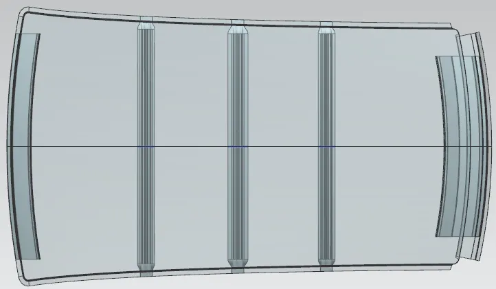
Overall Images
Top view:
Side view:

Isometric view:
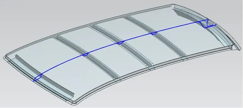
Conclusion:
The success rate of Criteria: The Design meets the requirements for both the snow load prediction and the bow load prediction. Therefore, there is no need to change the roof's design.