Roof Design
ROOF DESIGN
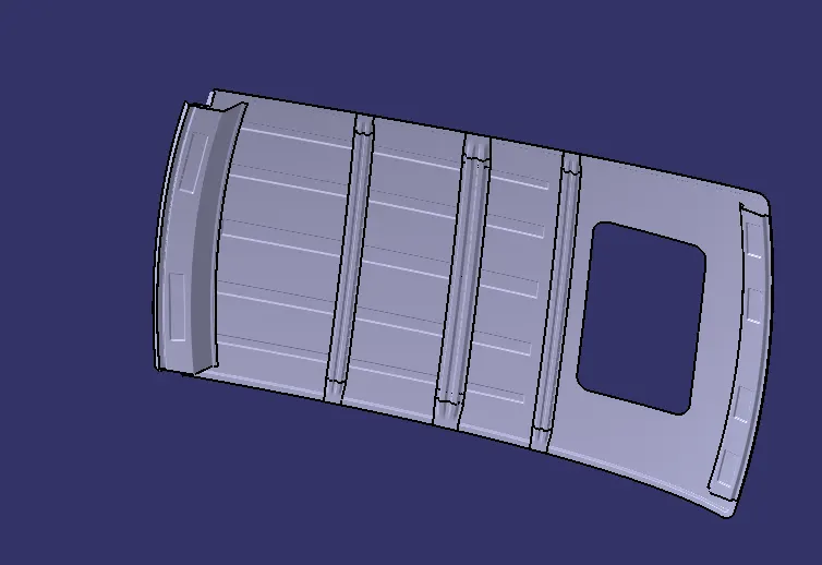
AIM:To create a ROOF ASSEMBLY from the given styling surface and to provide necessary support rails such as FRONT ROOF RAILS,BOW ROOF RAIL1,CENTRE ROOF WITH REINFORCEMENT,BOW ROOF RAIL2 & REAR ROOF RAIL and also to carry out HEAT DISTORTION CALCULATION AND SNOW LOAD PREDICTION calculation.Considering the result we can decide whether or not to give any additonal support such as longitudinal embosses on the roof.
ROOF OF THE CAR
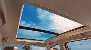
An automobile roof or car top is the portion of an automobile that sits above the passenger compartment, protecting the vehicle occupants from sun, wind, rain, and other external elements.Which is rested on the A,B,C pillars and in some cars there are even D pillars.There are at least three types of roofs commonly installed on cars, namely sunroofs, moonroofs, and also panoramic roofs. Sunroofs are often even called moonroofs. The three are actually different in terms of use and benefits.
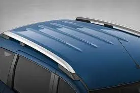
- Solid or hardtop: This is the fixed, solid metal roof that you see on most vehicles, often referred to as a “hardtop,” and it is generally the default roof option.
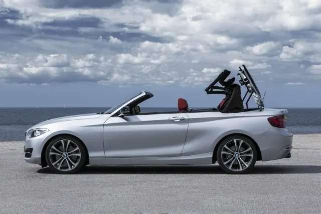
- Convertible: Sometimes also referred to as a “cabriolet,” a convertible gives drivers the option of going roofle
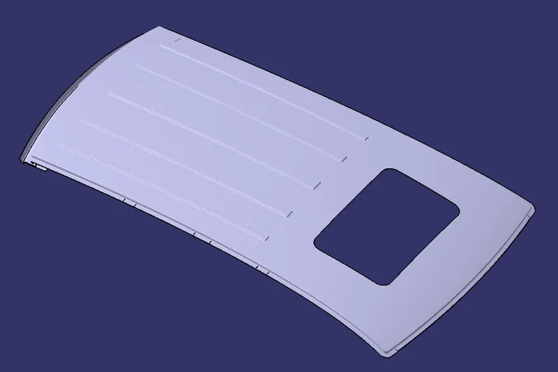
NORMAL ROOF
CONVERTIBLE ROOF
PANORAMIC ROOF
DESIGN CONSIDERATIONS
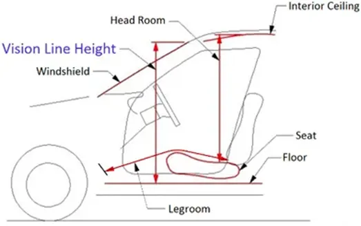
HEAD CLEARANCE
Head room clearance is the distance from the seat bottom to the roof of a car.It is also called 'torso room'.And for most of the cars a maximum value and minimum value is published because the seat can be adjusted in vertical way.
VISIBILITY CRITERIA
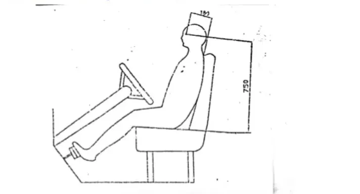
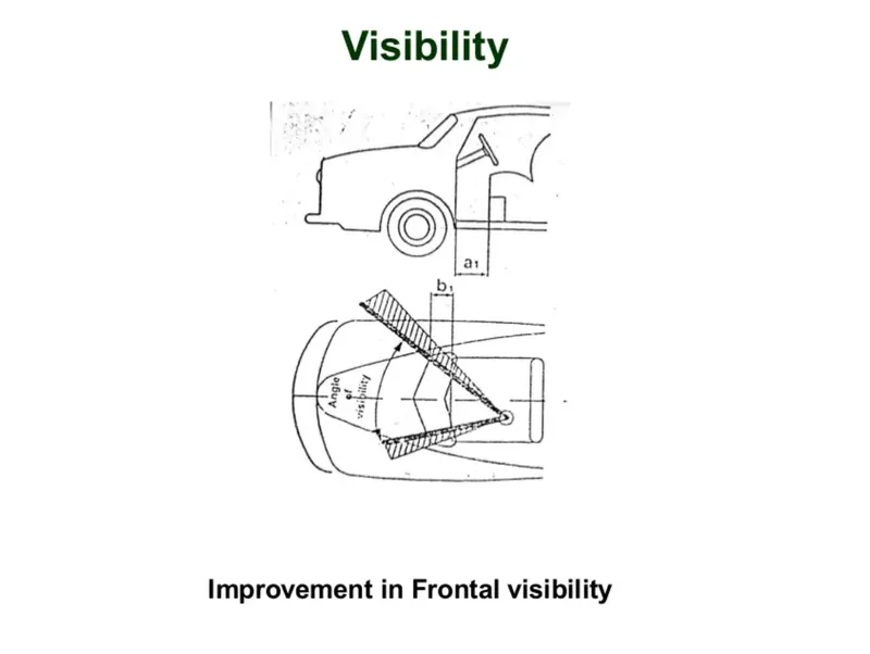
Depending on the shape of the roof there will be difference in the visibilty for the driver in both rear and front side through the wind shield.Good all round visibility is one of the main requirements of body design. Visibilty depends on the window opening and their relative position to the occupants. If occupant is placed close to wind screen the forward visibility is considerably improved but comfortable entry is adversely affected as dimention between pillar and seat is decreased requiring suitable shaping of the door, if possible.Downward visibility can be improved by positioning the driver as high as possible in realation to the lower edge of wind screen. Rearward visibility is achieved by increase in glass area required to maintain rear view vertical angle with back window. Figures below show eye position of driver, angle of visibilty and space between pillar and seat.
NUMBER OF BOW ROOF RAILS
Bow roof rails are one kind of roof rails that is provided below the roof for the support purpose.Number of bow roof rails are decided based the length of the roof and the need of the support.Usually for cars there will be two bow roof rails, one between front roof and centre roof and another between rear roof and centre roof.If the strength of roof is not satisfied after curvature analysis then we can even increase the number of the bow roof rails inorder to increase the support.In larger vehicles like suv,s there will be more bow roof rails inorder to provide additional strenth to the roof as its roof is much bigger compared to normal cars.
SUNROOF OR ALTERNATE ROOF TYPES
Sunroof or panoramic sunroof or convertible roof,there are different varieties of that can be made depending on the type of the car that we want to make.These types of roofs are usually found in premium vehicles but nowadays sunroofs are provided to economy calss vehicles too.
If sunroof is present that will change the position of the roof rails accordinglly inorder to provide more support that is needed to the parts that is nearby the cutoff part.So depending on whether sunroof is present or not, the position of the roof rails will aslo change accordingly.
SHAPE
Shape of the roof and roof rails are also a design consideration depending on which the load bearing and heat distortion of the roof will change.Some shape can withstand more load depending on its area moment of inertia.AREA MOMENT OF INERTIA is the resistance offered by a cross section towards any change in shape.The styling team will give us te shape of the roof outer but we still can increase its area moment of inetia by giving some longitudinal embosses and also the shape of the roof rails that we providing can be adjusted to a much better shape that can withstand more load which will increase the support to the roof and it will inturn increase the strangth of the roof.
MATERIALS
The whole car roof is made of sheet metal, so it is called as BIW. The roof outer panel is the aesthetic part of the roof and also it is the external part which covers the occupant or passenger compartment from the wind shield to the back door. But there are other materials alsop that is use in making of car roofs.which are,
- SHEETMETAL
- PLASTIC
- VINYL ROOFS
- SYNTHETIC FIBRE
- GLASS
JOINING TECHNIQUES
The parts of the roofs are attached to each other mainly using two joining techniques
- MASTIC SEALANT:The mastic sealant can act as a protecting layer between elements. The features of this sealant and how it works makes it different from the others. It forms a smooth exterior which makes the surface flexible while maintaining a hard plastic beneath the surface.Due to its flexibility, the sealant can be sued on different surfaces without preparing the surfaces first. To improve NVH (noise, vibrations, harshness), mastic sealants were provided on the inner panel to attach with outer panel. Here mastic points on the inner panel plays a major role to avoid Noise and Vibration into the cabin. NVH is measured by the instruments, namely microphones, accelerometer and force gauges, or load cells. Component and sub-assembly NVH tests are most commonly performed using a vibration shanker while entire vehicles usually on the test track or road simulator test-beds.
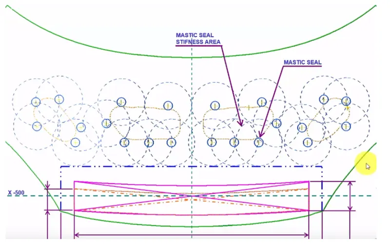
Mastic sealants are provided to the parts that are visible outside because it won't leave any marks on the external surfaces.For those parts where we will use mastic sealants as joining technique then we will maintain a 5mm gap between parts which will allow us to insert the mastic sealant.
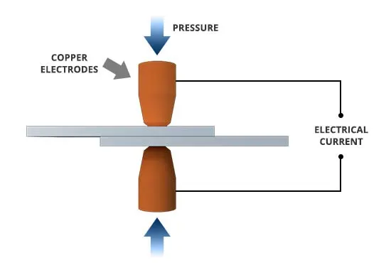
- SPOT WELDING:Spot welding (also known as resistance spot welding) is a resistance welding process. This welding process is used primarily for welding two or more metal sheets together by applying pressure and heat from an electric current to the weld area.Spot welding is done for the parts of the roof like ditch area which is not visible outside and for these parts there will be no clearance between provided as the parts should be in contact to carry out the welding process that is there will be 0mm clearance between parts.
CURVATURE ANALYSIS
Curvature analysis is carried out to find out the strength of the roof when in real time conditions,for example there is curvature analysis for both heat distortion and snow load.Which will give us an idea about how the roof will resist to the loads applied in these conditons.So thera are two types of curvature analysis which are,
- HEAT DISTORTION CALCULATION
- SNOW LOAD CRITERIA
HEAT DISTORTION CLACULATION
The Heat Deflection Temperature (HDT), or Heat Distortion Temperature, is a measure of a polymer's resistance to alteration under a given load at an elevated temperature. It is also known as the 'deflection temperature under load' (DTUL) or 'heat deflection temperature under load (HDTUL)'. Predicting heat distortion for the roof is important since it is exposed to the heat for a long time and high temperature will affect the roof structure if the designing does not confirm with the heat distortion criteria. the study helps to determine the position of roof to provide strength to the route to avoid bending and deflection of the roof due to heat. bow curvature study you see following formula will help best check whether the boardroom potion important required strength of roof.
Bow–Roof Prediction Formula,
W = [1.73 x 10^ (-3) x L] + [1.85 x 10^ (-8) x (R^2)/t] + [ 1.10x10^ (-3) x l] - 2.68
Were,
L = Roof Length in X-Direction[mm](Roof dimension in 0-Y)
R = Roof curvature
R = 2(Rx*Ry)/(Rx+Ry)
Rx = X curvature
Ry = Y curvature
t = Roof plate thickness [mm]
l = Bow Roof Span [mm]
Judgment Condition
OK< 2.7
SNOW LOAD CRITERIA
This evolution is performed in cold regions where snow a occurs. roof design must pass through the calculation to ensure that it has sufficient stiffness to withstand the load due to the accumulation of snow over the roof.In those parts of the world snow will be accumulated over the roof when the vehicle is in rest conditions under snow fall and the vehicle roof must have enough strength to carry the snow load and the curvatuire analysis will give us insights about where we need additional support and whether the roof is strong enough or not.
Qr = [Iyxt2] / [α x s x [(Rx + Ry)/2]2 x 10-8]
Were,
α = My x Lx2 x 10-12, My = Y(Ly-Y)
Judgement condition = Qr ≥ 3.1
250 ≤ s ≤ 380
(S varies depends on the Input)
t = Roof plate thickness [mm]
Ly= Distance between the Front and rear roof Rails on the Vehicle along 0Y [mm]
Length of Roof panel with the centre point between Roof rails Front /Rear as the reference point of the front and the rear.
Lx= Distance between the Left and Right end of the roof on the Roof BOW [mm]
Width of the roof panel exposed on the surface.
Y = Distance front Roof Rail to Roof BOW [mm]
s= Distance for which Roof BOW bears divided load [mm] s = L1/2 + L2/2
Iy = Geometrical moment of inertia of Roof BOW (Y cross section) [mm4]
Rx = Lateral direction curvature radius of roof panel Y cross section on Roof BOW [mm]
Roof panel curvature Radius of the Length Lx in Front view
Ry = Longitudinal Direction curvature radius of the Roof panel X cross section on Roof BOW [mm]
Roof panel X curvature radius of length s in Side view
PROCEDURE
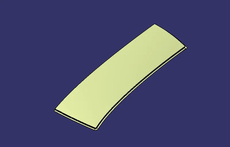
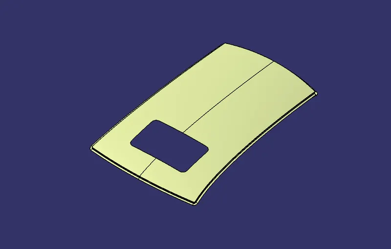
ROOF OUTER PANEL
- Roof outer panel must be created according the master section in front and rear part
- Extract the top part of the roof from the given styling surface
- Split it using a datum plane through the middle
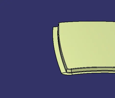
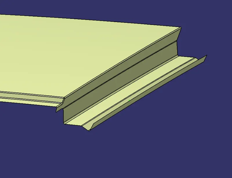
- Then create front and rear ditch areas according to the master sections
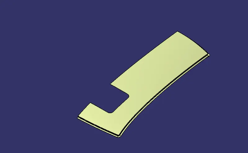
- If needed can provide sun roof between the centre roof rail and front roof rail
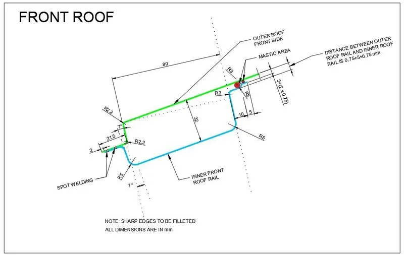
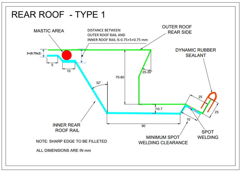
- The ditch areas of the roof outer must craeted as per the master section in the given images above and the green part is the roof outer.For creating the ditch area tools like multi section,sweep are used and they are joined together using shape fillet with applying suitable fillet radius
- Then the half part must be extrapolated and split using the datum plane and again apply symmetry using the same plane that is used to split the surface to get the full outer roof
- Then apply thickness of 0.75mm to inside of the surface
FRONT SIDE DITCH AREA
REAR SIDE DITCH AFREA
FRONT ROOF RAIL
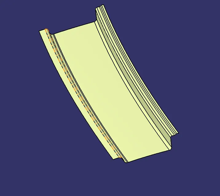
- Extract the surface of the ditch area and also the roof outer and offset the ditch area to 1.5mm and the roof outer 32mm as per the master section
- Then create the sweeps accordinlgy as per the master section
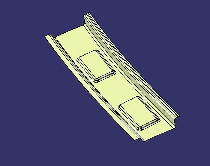
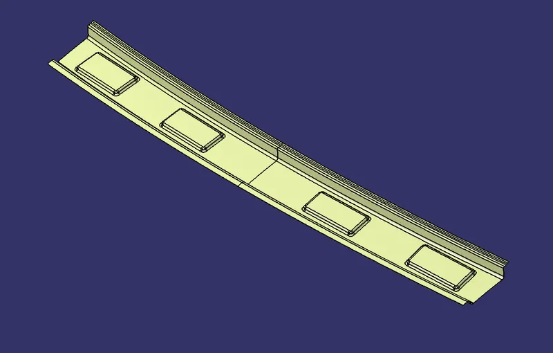
- Provide any embosses for additonal strength if needed
- The surface is splitted on the extreme using a datum plane to leave a spacing from the side part of the roof
- We create this for half part and follow the same steps for the roof outer to use symmetry and create the final surface
- Then apply thickness of 0.75mm to inside in the direction of roof outer so that it will come in contact in ditch area so that we can acrry out the spot welding there
- Sweeps are joined together using shape fillets
DRAFT ANALYSIS
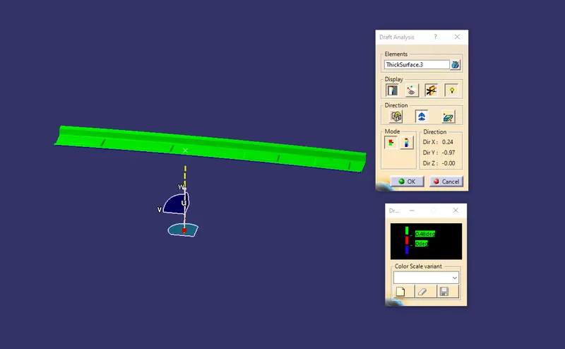
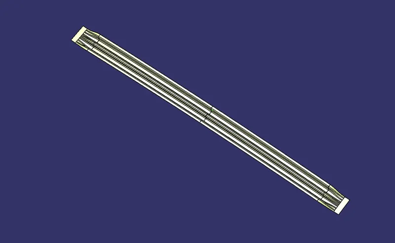
BOW ROOF RAIL 1
- Bow roof rail 1 is created by creating a datum plane in the middle curve of the surface uisng noemal to curve option by considering the master section given and also by assuming the values which are not given in the master section
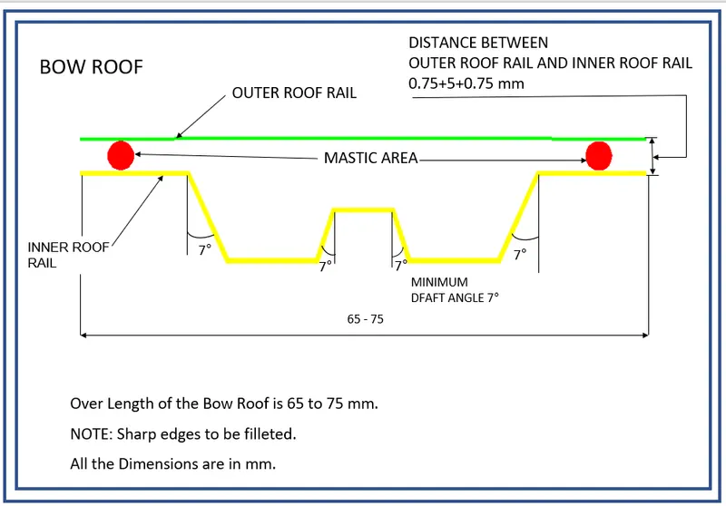
- The datum plane is created by creating a point on which we have control to locate the emboss and also we can relocate it later
- Then the part is plitted using a datum plane from the extreme and we extract the ditch area and offset it to a 1.5mm distance
- Then split the ditch area using two planes that are created in the middle of the extreme edges the above part
- After create splines between the end point of both splines in both ends
- Then using multisection create a surface between and join then tigether using join tool
- Then follow the same steps as in the previous part to create the full surface and apply thickness to inside
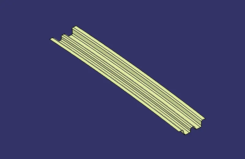
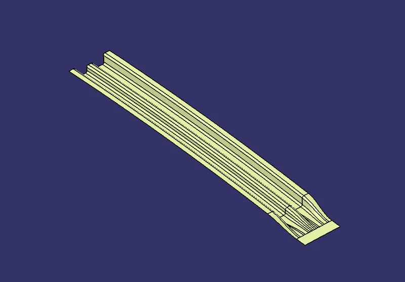
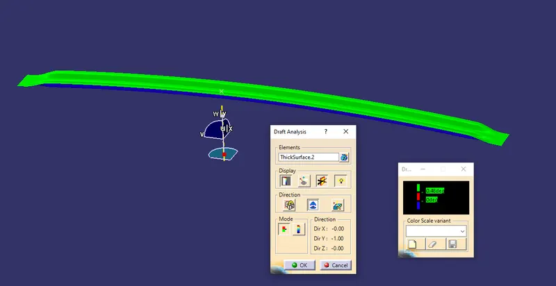
DRAFT ANALYSIS
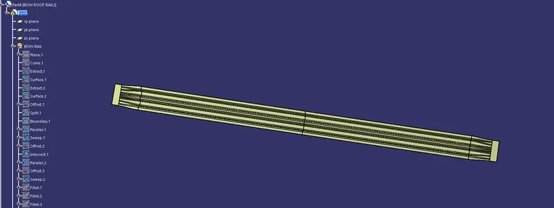
BOW ROOF RAIL 2
- Bow roof rail 2 is created in the same way as bow roof rail 1 but the location will be changed and the location will be in between centre roof rail and rear roof rail
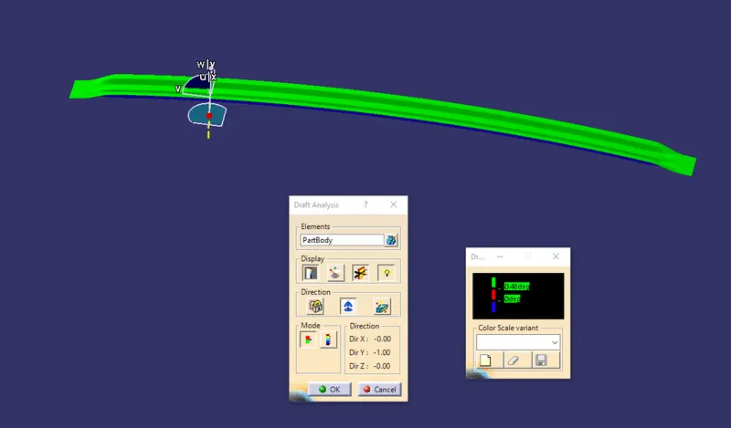
DRAFT ANALYSIS
CENTRE ROOF RAIL WITH REINFORCEMENT
- Centre roof is to be created as per the master section given but reinforcement also should be c reated because our roof consists of sun roof
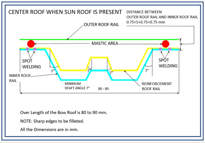
- Yellow part in the master section is the reinforecment
- It will be created as a seperate part and it will be at a distance of 6.5m from the roof outer and the thickness will be done to inside so that there will be a 5mm gap between thicknesses so that mastic sealant can be provided
- REINFORCEMENT PART
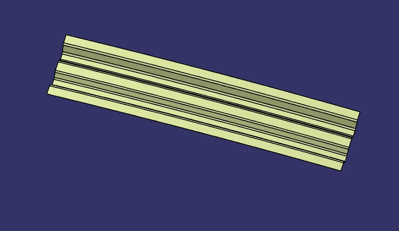
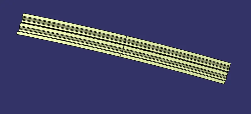
- CENTER ROOF RAIL PART is created in same method as we have done for bow roof rail but dimensions are changed as per the master section
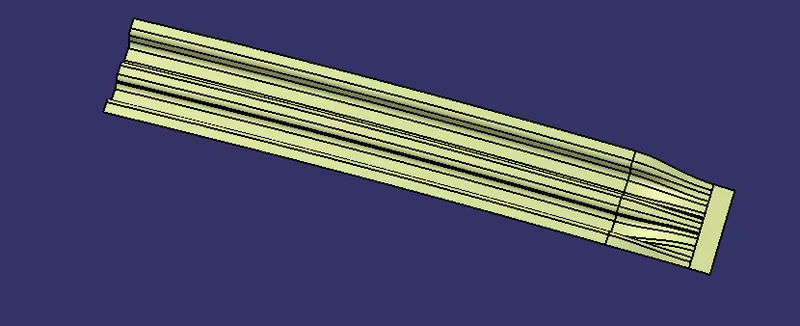
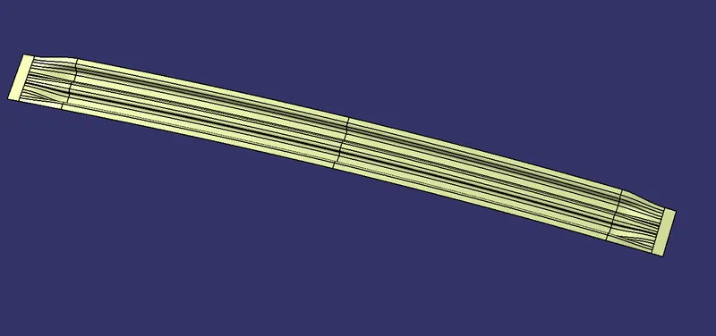
CENTRE ROOF RAIL WITH REINFORCEMENT
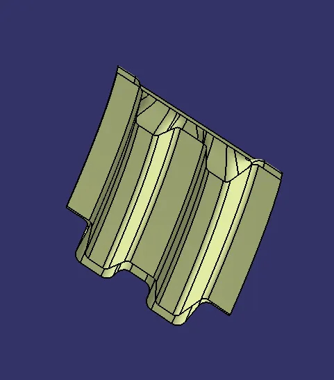
DRAFT ANALYSIS
REINFORCEMENT PART
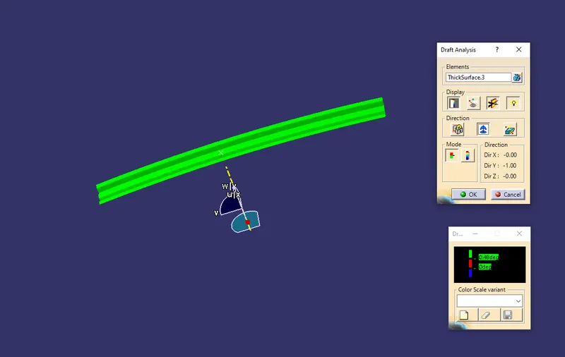
CENTRE ROOF RAIL PART
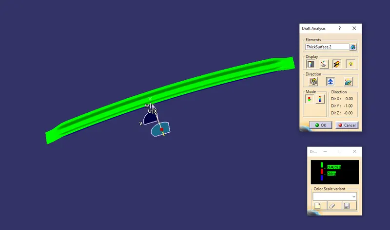
REAR ROOF RAIL
- Rear roof rail part is created as per the multi section given and the steps followed to created the part is same as that of the front roof rail
- The blue part in the master section is to be craeted and the thickness should be given to inside and the dimesions which are not given can be assumed
- Embosses are given to provide additional strength for the rear roof
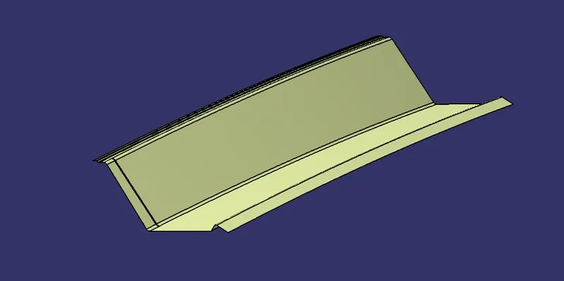
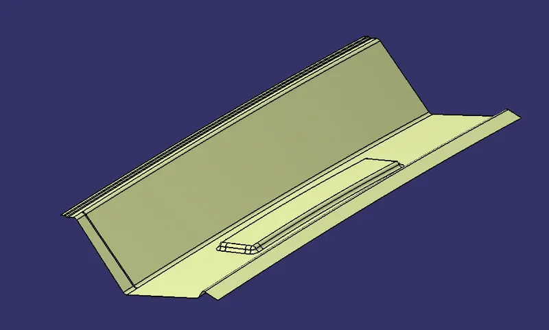
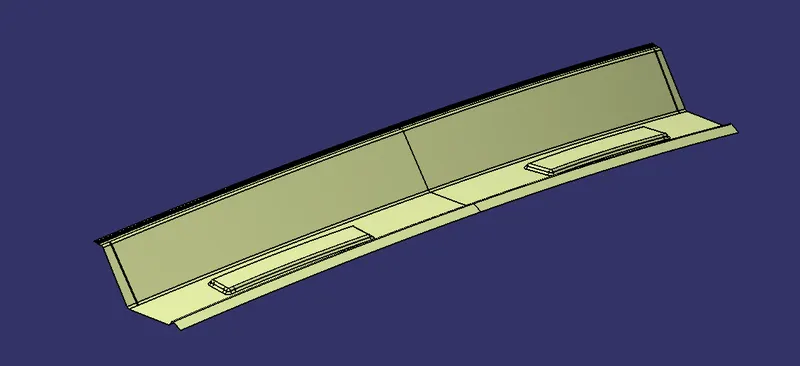
DRAFT ANALYSIS
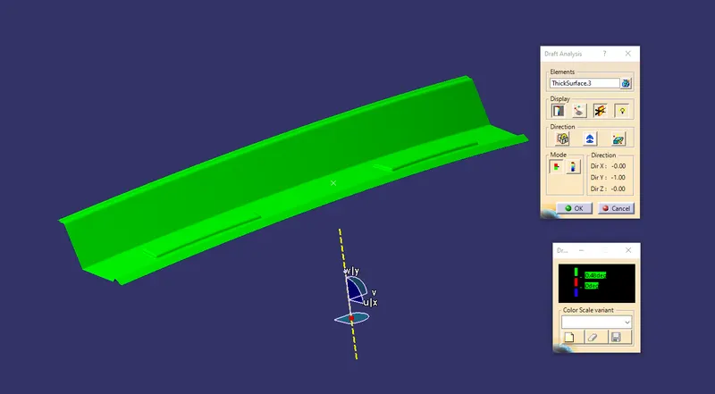
HEAT DISTORTION CALCULATION
- Heat distortion calculation is done by creating a line through the centre (0Y)using datum planes and offseting it to 300 mm(3Y)
- An 100 mm offset is created on both side of 3Y
- Centre line is created by creating centre points for each rails and that line is also offseted 100mm to both sides
- Then we will create intersection points and project them to the surface to find out the values of Rx and Ry
- Then using equations given we will find out the values and make sure it satisfies the conditions or not
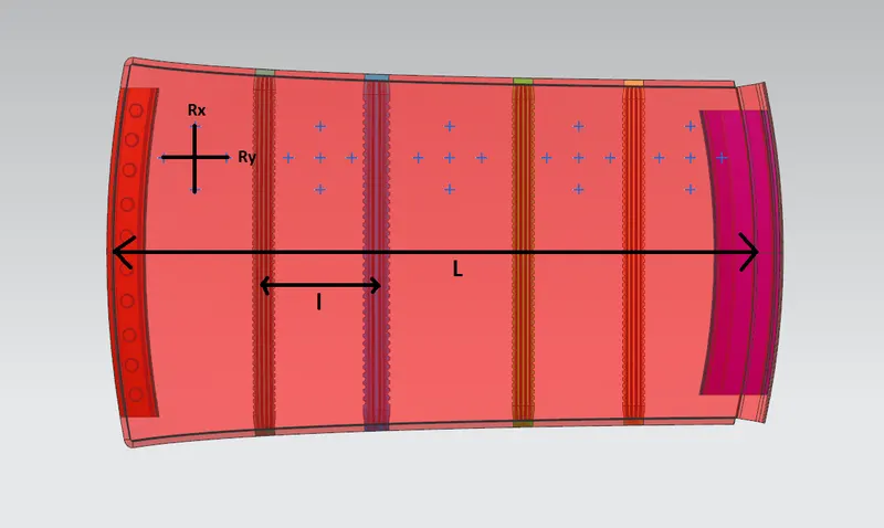

CASE 1:BETWEEN BOW ROOF 1 AND CENTRE ROOF RAIL
CASE 2:BETWEEN CENTRE ROOF RAIL AND BOW ROOF RAIL 2
CASE 3:BETWEEN BOW ROOF RAIL 2 AND REAR ROOF
Here the judgement condition is w must be less than 2.7 and all three cases satisfies the conditon
SNOW LOAD CRITERIA CALCULATION
- Snow load criteria is calculated by creating lines at offset distance of 100mm around OY
- Vertical lines are the same
- create intersection points and project them to the surface and measure the values needed
- Do the calculation using the equations given
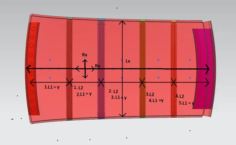

HERE THE JUDGEMENT CONDITOIN IS
-Qr ≥ 3.1,It is satisfied by both the cases
-250 ≤ s ≤ 380 this condition is not satisfied by one of the cases which suggest that the strength is of the roof is not enough at some places
CONCLUSION
After carrying out the curvature analysis it is found out that even if it is satisfying all the heat distortion criteria,it is not satisfying some criteria for the snow load calculation which means that ṭhe strength might not be sufficient at some places for the roof.So we will provide longitudinal embosses o the roof outer sur̥face so that it will improve the strength of the roof oute panel which will help to increase its snow load bearing capacity
FINAL ASSEMBLY OF THE ROOF