Roof Design
Challenge 5: Roof Design
The roof is one single panel which is normally 0.75 mm thick. An automobile roof is the portion of an automobile that sits above the passenger compartment, protecting the vehicle occupants from sun, wind, rain, and other external elements. The roof is provided with reinforcements which improves its strength and stiffness minimizing its failure under different load conditions. These reinforcements are:
- Front Roof Rail
- Bow Roof (1 & 2)
- Center Roof Rail
- Rear Roof Rail
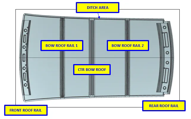

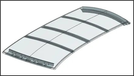
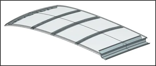
There are cars like vans that could have more reinforcements. Typically, the bow roofs are positioned in the flattest area of the car because this region is kind of weak. To improve the strength of the flattest regions of the roof, you can make the flat region kind of tilted or introduce some Bow Roofs.
ROOF MANUFACTURING TECHNIQUES
Bending
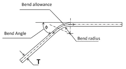
The bending die is one of the most used stamping dies due to its ability to form different channel structures and other shapes, but also because such shapes increase the panel stiffness by increasing its moment of inertia. The bending process is achieved through applying a bending moment on the blank. The most important thing to compute is the minimum bend radius to the blank thickness . To evaluate the minimum bending radius, one can compute the strain through the formula for any location within the blank thickness, i.e. at a distance of R.
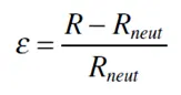
where is the radius measured from the neutral axis (or line).
Deep Drawing
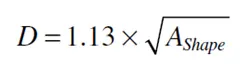
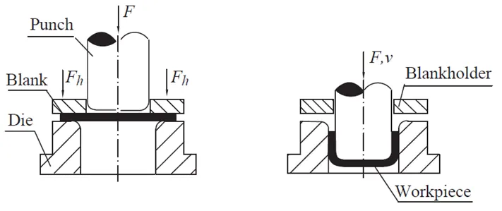
The drawing of metal or ‘Deep Drawing’ is the process by which a punch is used to force sheet metal to flow between the die cavity and punch surfaces. Typically, the deep drawing process can generate final shapes that do not require subsequent steps. It is possible to produce a final workpiece using minimal operations and generating minimal scrap when compared with other stamping processes. Deep drawability is often expressed as the blank diameter to the punch diameter, and the number of needed successive drawing processes is described by the ratio of the part (cup, pan) height to its diameter. Additionally, one can compute the required blank size to produce a certain deep drawn shape through the formula, where is the area of the final produced shape.
A schematic illustration of these deep drawing processes is shown in Figure.
Resistance Welding (Spot Welding)
Resistance welding is accomplished when a current is caused to flow through the electrode tips and the separate metal panels (to be joined). The resistance of the base metal to the current flow causes localized heating in the joint, leading to the formation of the weld nugget at the interface between the two panels. The heat generated is simply described by Ohm’s law which means that the heat is the product of the current value squared and the interfacial resistance (caused by the air gap between the two panels). The resistance welding process is achieved through two welding electrodes (upper and lower), while the joined panels are inserted between them, as displayed in Figure.
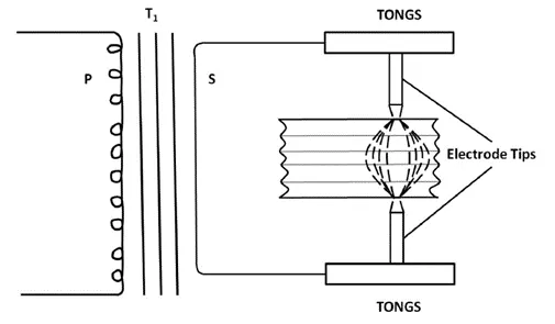
Another important feature of the resistance welding process is that it forms internal joints (nuggets) within the joined panels. In MIG and TIG welding, the joint is external to the joined metals. At the same time spot welding is the most used welding practice in automotive manufacturing, a completed body shell features at least 4000 – 5000 spot welds. The resistance welding process includes different variations depending on the shape of the electrode. The main types are:
- Spot welding
- Projection welding
- Seam welding
FRONT ROOF RAIL
Front Roof Rail is the part which joins with the Windshield Glass and the Body Side Outer. A Front Roof Rail is an additional commodity which is being given as a reinforcement and has certain features which will be supporting the bracket map lamp and the room lamp which is being mounted on this rail.
Front Roof Rail Master Section
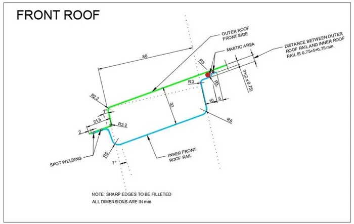
Summary of Design Parameters, Dimensions and Features
|
Parameter/Feature |
Explanation |
Dimensions |
|
Deep Drawing (32 mm Depth) |
Depends upon the Visibility Criteria. |
32 mm |
|
Windshield Glass Mounting Area (21.5 mm Flange Length) |
It should be considered to prepare flange that will be the windshield glass surface. This dimension considers several factors like: Rubber Paste (minimum thickness is 5 mm. + Molding (minimum most flange is 8 mm) + Windshield Glass Dimension + Rubbers Dimension. |
21.5 mm |
|
Front Roof Rail Length |
Depends upon the Visibility Criteria. |
80 mm |
|
Roof Thickness |
|
0.75 mm |
|
Minimum Radius |
Always on steel parts, you should have a minimum (base) radius of 3 mm + Thickness. In this case, according to the project rules, Th = 0.75 mm. Then, minimum radius to be used in all the fillets should be 3.5 mm. |
3.5 mm |
|
Tool Opening Angle |
According to the project rules. |
Min 7° |
|
Bow Roof Height |
According to the project rules. |
12-15 mm |
|
Spotweld Offset Distance |
According to the project rules, it should be 0.75*2 + 0.2
|
1.7 mm |
|
Spotweld Common Land Area |
According to the project rules. |
15 mm |
|
Pitch between 2 Spots |
According to the project rules. |
20-25 mm |
|
Mastic Sealant Offset Distance |
According to the project rules, it should be 0.75*2 + 5
|
6.5 mm |
Visibility Criteria
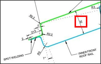
The engineer should try to obey this criterion trying to keep Front Roof Rail Length as 80 mm and Deep Drawing Depth as 32 mm. If these values are kept, then we will gain enough Headroom space.
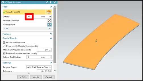
Deep Drawing Depth
This design was started by offsetting the untrimmed surface to the Deep Drawing distance of 32 mm downwards.
Windshield Glass Mounting Area
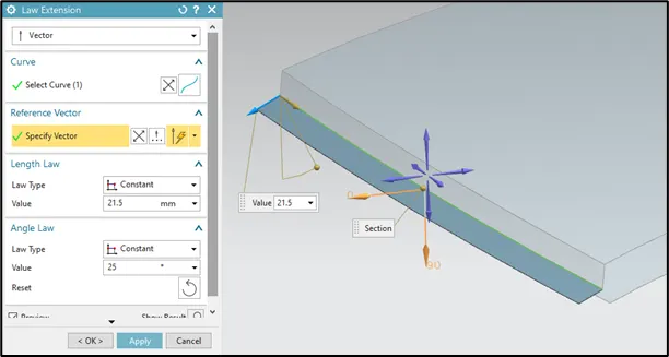
It is also needed to draw the 21.5 mm flange for Windshield Glass Mounting Area.
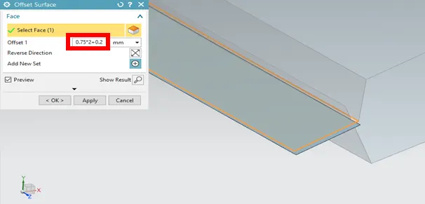
Offset Distance for Spot Welding
It should be provided enough offset distance between Front Roof Rail’s Outer and Inner flanges for Spot Welding purposes.

Front Roof Rail’s Inner Panel
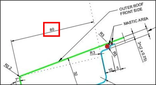
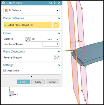
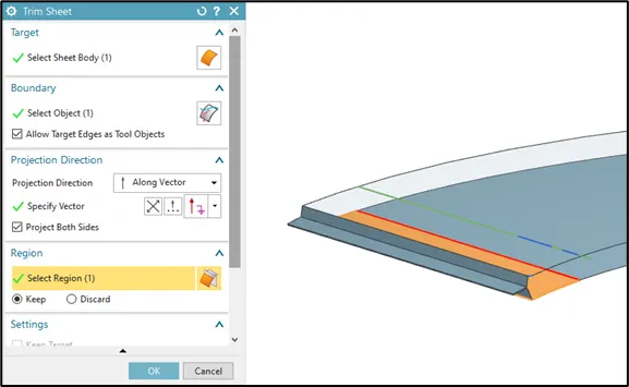
First, it was created this 80 mm dimension used as reference to create Offset Surface.
Mastic Sealant Flange
Create the Mastic Sealant Flange by offsetting surface to a distance of 6.5 mm.

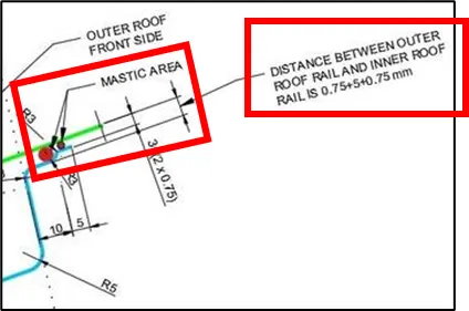
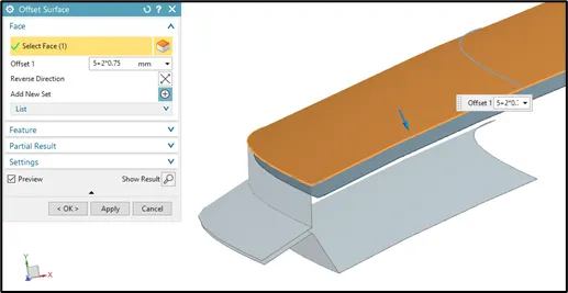
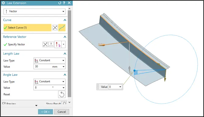
For Front Roof Rail’s Inner Panel, it was given an angle of 8° (Min Tooling Angle is 7°) to satisfy the Draft Analysis.
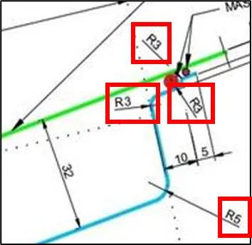
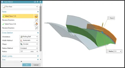
It was applied Face Blends using fillet radius values indicated in Master Section.
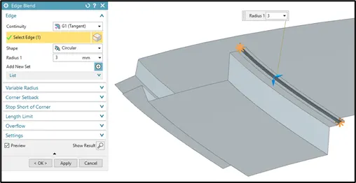
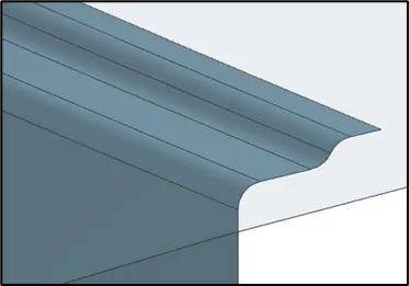
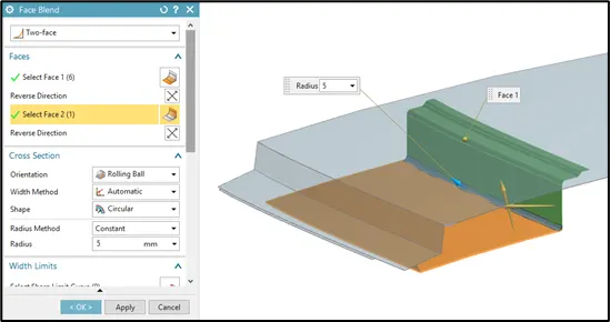
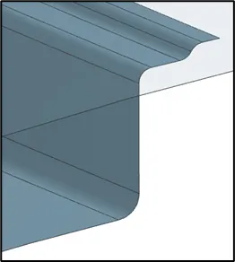
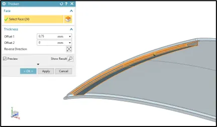
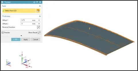
Thicken Front Roof Rail (Inner Panel) by 0.75 mm upwards and Roof Outer Panel by 0.75 downwards.
Roof Ditch Area
The Ditch Area is the extended portion of the main roof covered by other BIW panels. The rail supports of the roof are attached to the Ditch Area using spot welds.
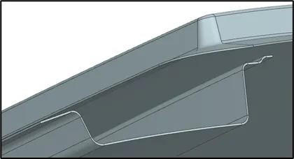
For Ditch Area, it was used Draft Angle. It is supposed to be more than 3°. Minimum Draft Angle for sheet metal components, especially for steel should be 7°.
For Front Flanges, it was given a tool opening angle of 7° as indicated in Master Section.
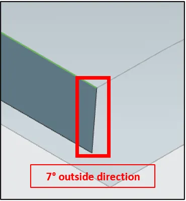
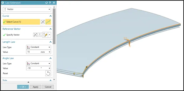
For Side Flanges, it was given a value of -10°.
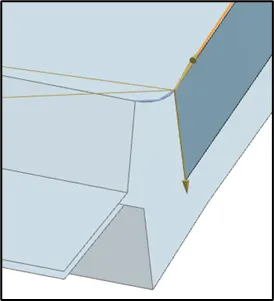
Added fillet radius of 2.2 mm as indicated in Master Section.
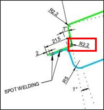
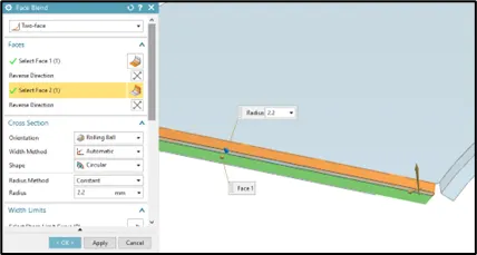
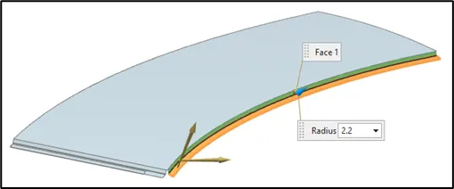
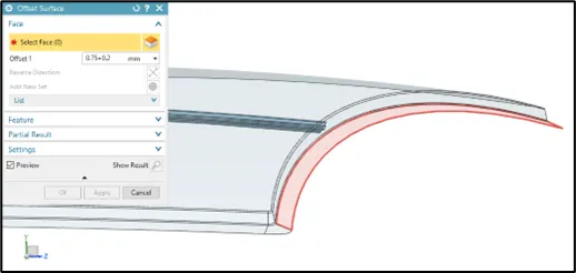
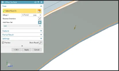
Finally, it was also provided Offset Distance for Spot Welding of 0.75 + 0.2 = 0.95 mm as indicated in Master Section.
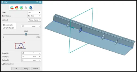
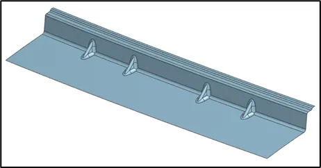
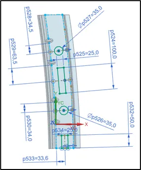
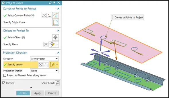
Creation of Embosses for the Front Roof Rail
Adding final strengthening features like Darts and Embosses.
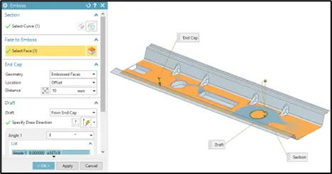
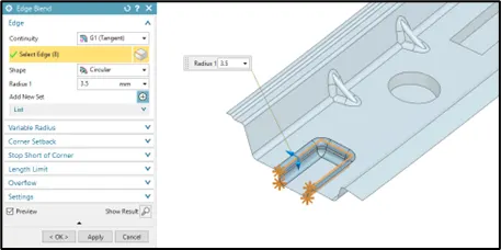
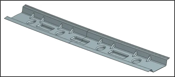
REAR ROOF RAIL
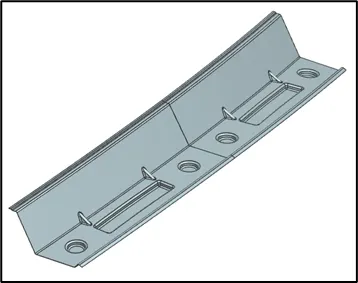
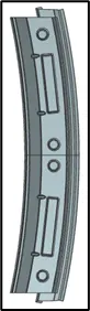
This part joins the back door and the body side outer. The rear roof provides enough space for back door hinge placement. The field of vision and head room clearance are to be considered while dimensioning.
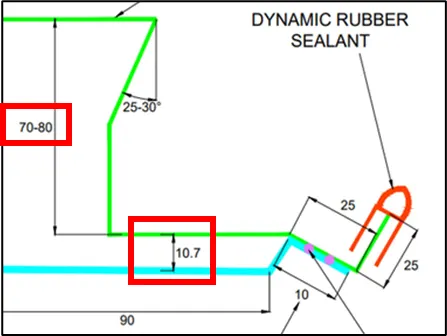
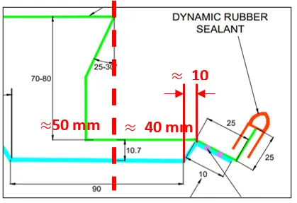
Master section of the Rear Roof Rail
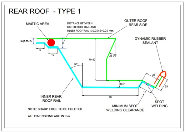
First, it was offset the base surface to a distance of: 75 + 10.7 = 85.7 mm.
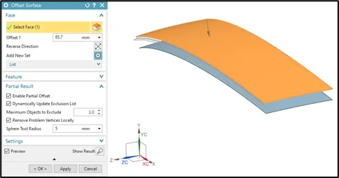
Then, it was extended the offset bottom sheet to create other flanges.
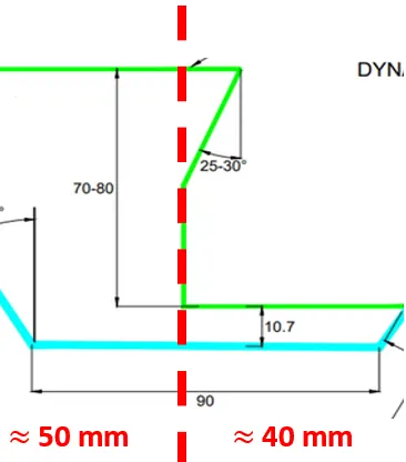
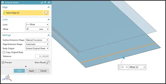
It was created this top flange. This flange will result in negative draft angle further but is needed as indicated in Master Section.
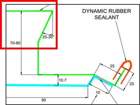
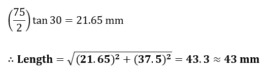
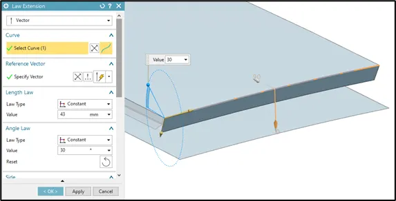
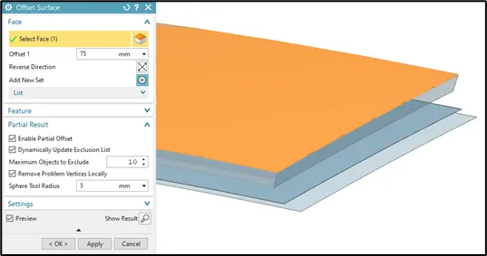
Offset base surface to distance of 75 mm.
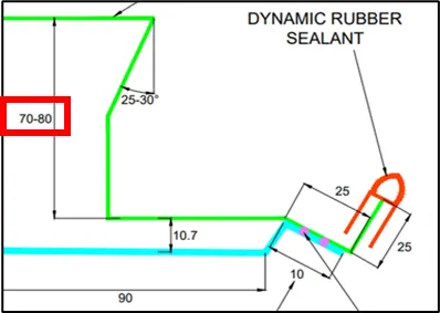
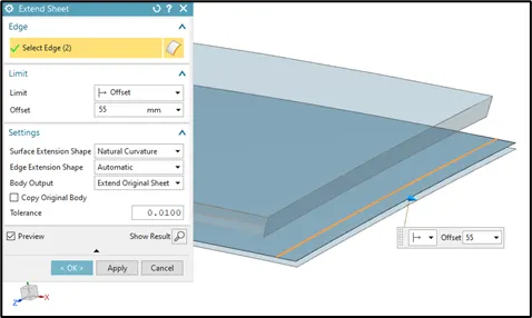
Extended offset middle sheet to create other flanges.
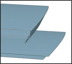
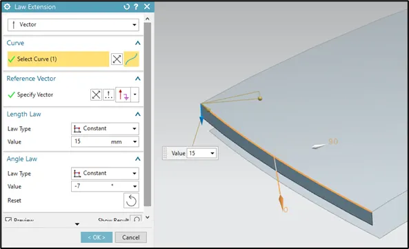
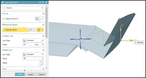
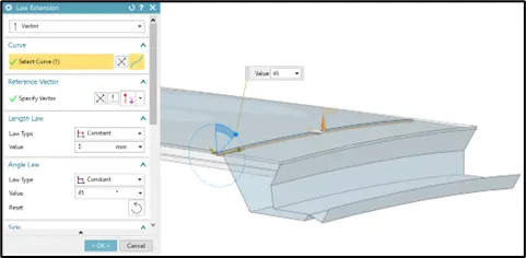
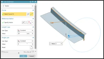
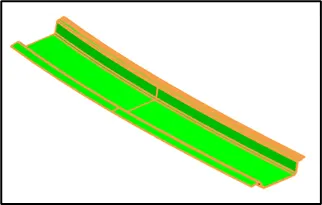
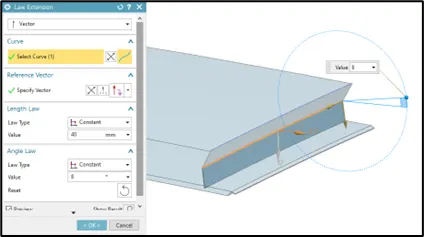
Using Law Extension command, flanges shown below were created.
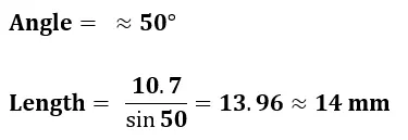
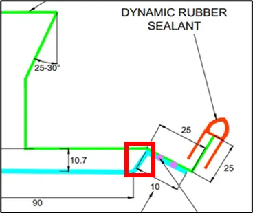
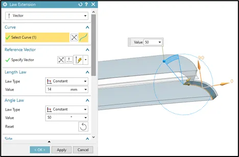
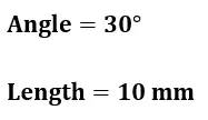
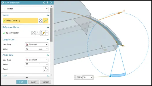
Then, it was offset the last surface to Minimum Spotweld distance: 0.75*2 + 0.2 = 1.7 mm as indicated in Master Section.
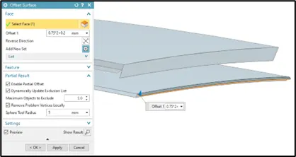
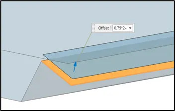
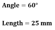
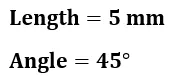
Then, created ‘Law Extension’ surface using 8° angle (Min Tooling Angle should be 7°) to satisfy the Draft Analysis.
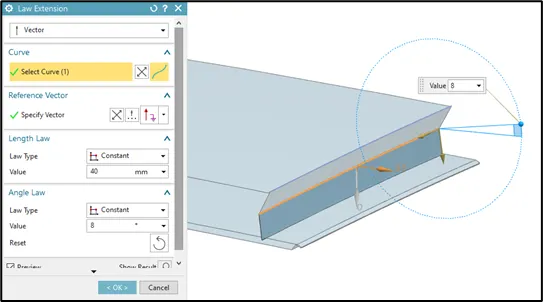
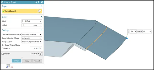
Extended the flange sheet shown below by 15 mm.
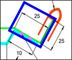
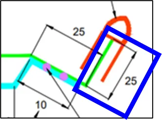
Then, created another flange using Law Extension command.
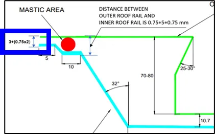
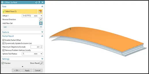
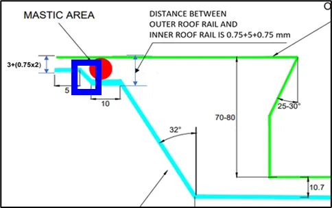
Again, offset the base surface by a distance of: 3 + (0.75*2) = 4.5 mm
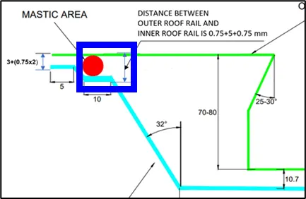
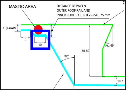
Mastic Sealant Area
As indicated in Master Section, offset the base surface by a distance of: 5 + (0.75*2) = 6.5 mm
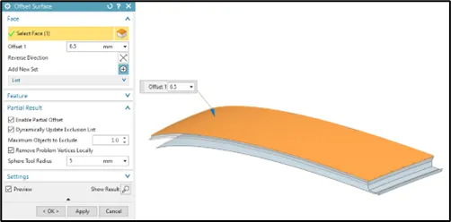
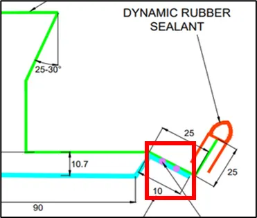
Offset the edge of bottom sheet by distance of 90 mm using ‘Offset Curve in Face’ command. Trim the sheet using ‘Trim Sheet’ command.
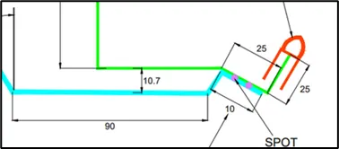
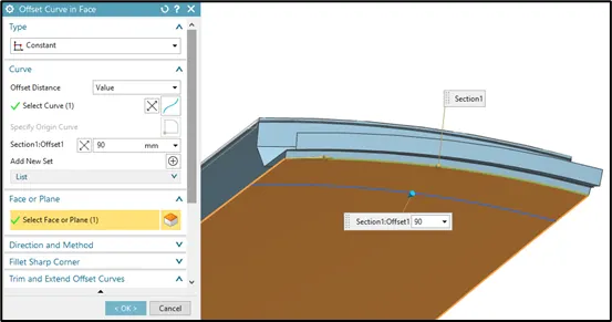
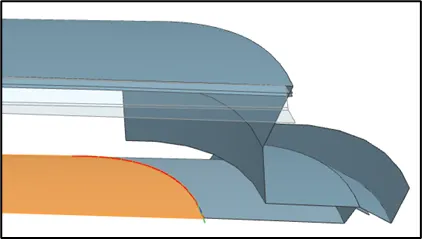
Create another flange using Law Extension command.
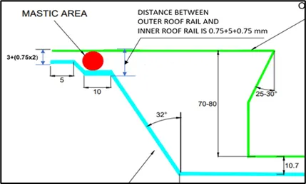
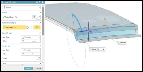
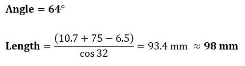
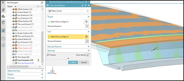
Offset the edge of the sheet by distance of 10 mm using ‘Offset Curve in Face’ command.
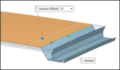
Created another flange using Law Extension command.
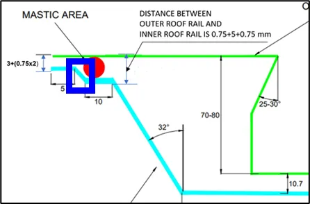
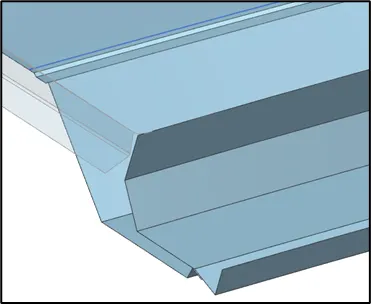
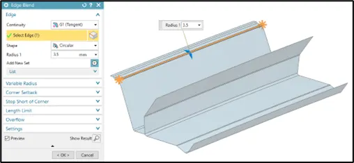
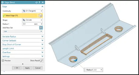
Added fillet radius of 3.5 mm.
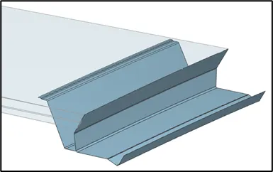
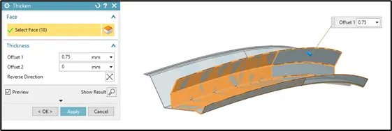
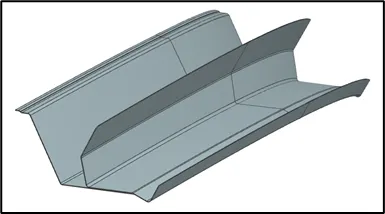
Thicken Rear Roof Rail’s Inner Panel by 0.75 mm upwards.
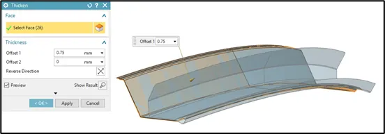
Thicken Rear Roof Rail’s Outer Panel by 0.75 mm downwards.
Creation of embosses for the Rear Roof Rail
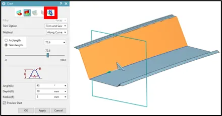
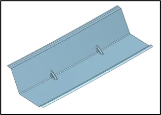
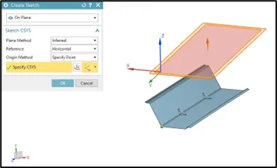
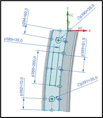
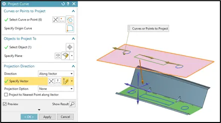
Now, we can go and create again the Dart and Emboss features.
BOW ROOFS
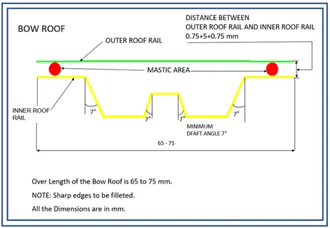
Bow Roof Rails are given to improve the torsional stiffness and load-bearing capacity of the roof structure. The number of bow roofs provided will depend upon the overall dimensions of the roof. They are attached to the outer panel using mastic sealants. The positioning of bow roofs is done based on curvature study. Bow Roof Rails and Centre Roof Rail are joined with the help of Mastic Sealant. It is not allowed to use the spot welding because it can damage Class A Surface areas of the Roof.
This design will consist of only CTR Roof Rail and 2 Bow Roofs.
BOW ROOF RAIL 1
Master section of Bow Roof
Proposed Cross Section Dimensions
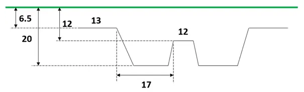
We need to have 5 mm for Mastic Points.
So, Offset value should be: (0.75 mm * 2) + 5 mm. It will create an offset surface at distance of 6.5 mm.
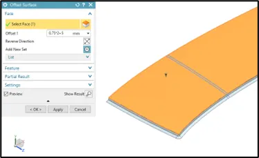
The other two offset surfaces were created based appropriate Bow Roof Rail’s height that result in adequate MOI value.
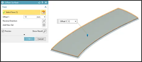
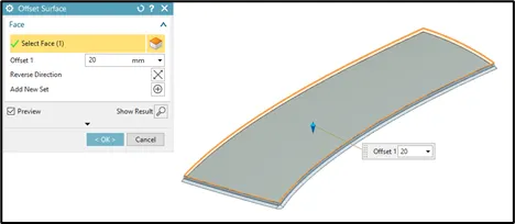
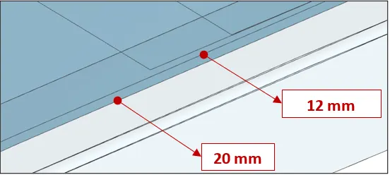
Offset Curves were created based on dimensions proposed for cross section to get the adequate Bow Roof Rail’s width of 70 mm (65 to 75 mm).
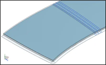
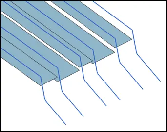
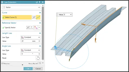
Adding Tooling Angle of 8° for all Law Extension sheets.
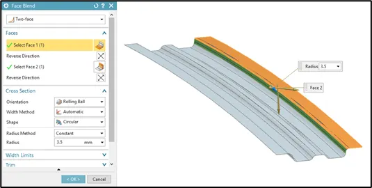
Face Blends created using Min Fillet Radius of 3.5 mm.
In this case, we used Studio Surface to create Bow Roof Rail 1. Then we verified no gaps were generated.
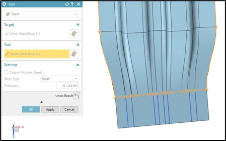
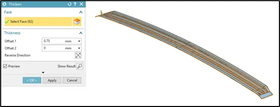
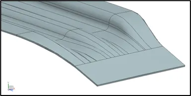
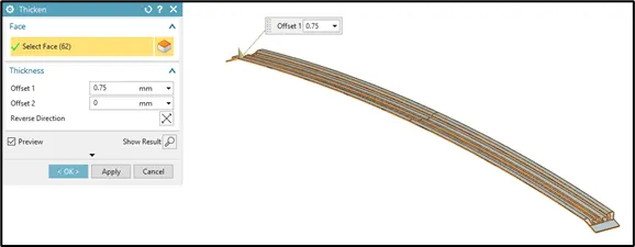
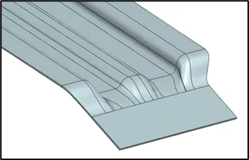
Finally, thicken by 0.75 mm upwards.
CTR BOW ROOF
Master section of CTR Bow Roof
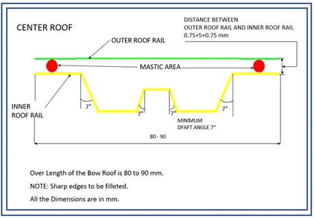
Proposed Cross Section Dimensions
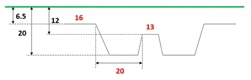
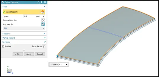
We need to have 5 mm for Mastic Points. So, Offset value should be: (0.75*2) + 5. It will create an offset surface at distance of 6.5 mm.
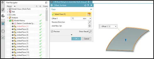
The other two offset surfaces were created based appropriate Bow Roof Rail’s height that result in adequate MOI value.
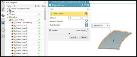
Offset Curves were created based on dimensions proposed for cross section to get the adequate Bow Roof Rail’s width of 85 mm (80 to 90 mm).
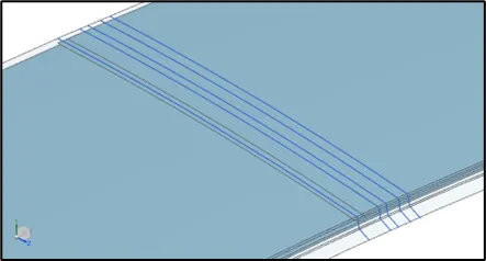
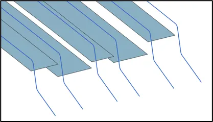
CTR Bow Roof flanges were created using a Tooling Angle of 8° to satisfy the Draft Analysis (Min Draft Angle is 7°).
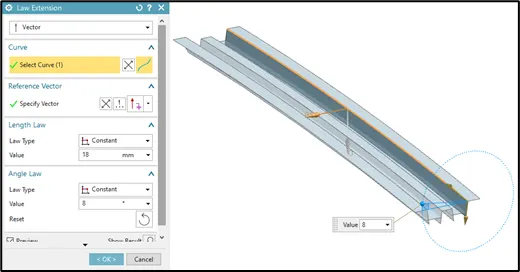
The Face Blends were created using Min Fillet Radius of 3.5 mm.
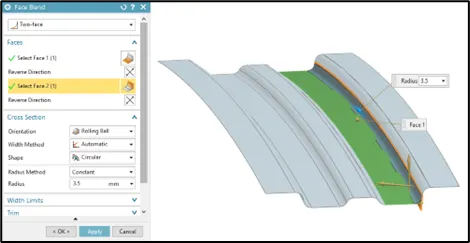
Using ‘Through Curve Mesh’ command to create CTR Bow Roof Rail. Then, verified that no gaps were created.
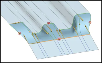
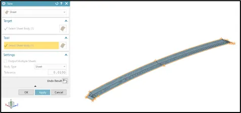
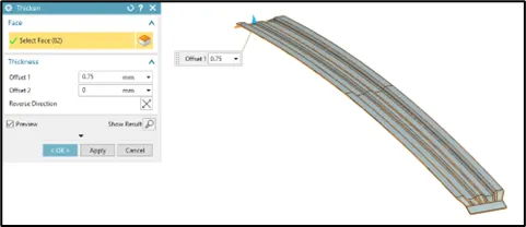
Thicken CTR Roof Rail by 0.75 mm upwards.
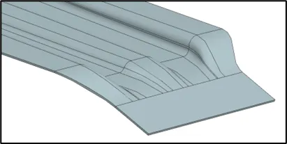
BOW ROOF RAIL 2
Master section of Bow Roof
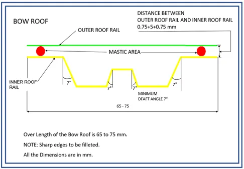
Proposed Cross Section Dimensions
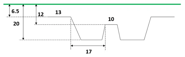
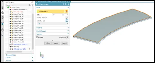
We need to have 5 mm for Mastic Points. So, Offset value should be: (0.75 mm * 2) + 5 mm. It will create an offset surface at distance of 6.5 mm.
The other two offset surfaces were created based appropriate Bow Roof Rail’s height that result in adequate MOI value.
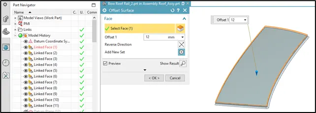
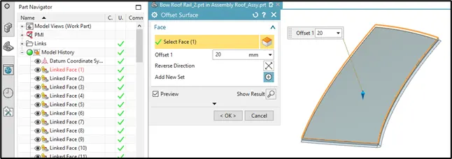
Offset Curves were created based on dimensions proposed for cross section to get the adequate Bow Roof Rail’s width of 70 mm (65 to 75 mm).
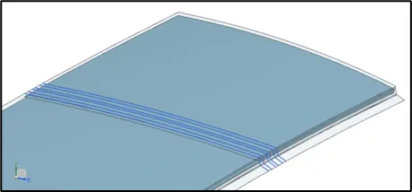
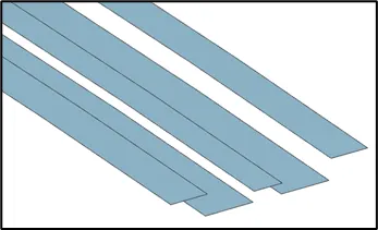
CTR Bow Roof flanges were created using a Tooling Angle of 8° to satisfy the Draft Analysis (Min Draft Angle is 7°).
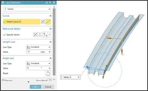
The Face Blends were created using Min Fillet Radius of 3.5 mm.
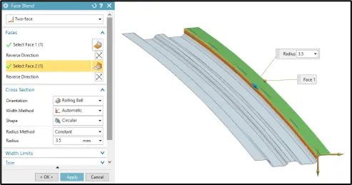
Using ‘Through Curve Mesh’ command to create CTR Bow Roof Rail. Then, verified that no gaps were created.
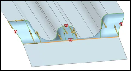
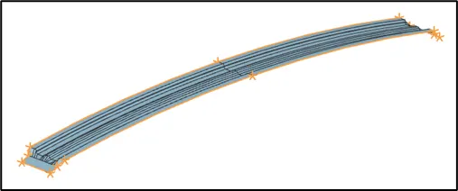
Thicken CTR Roof Rail by 0.75 mm upwards.
BOW ROOF POSITIONS
Curvature Study based on Bow Roof Prediction Calculation
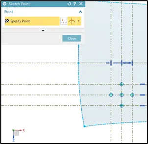
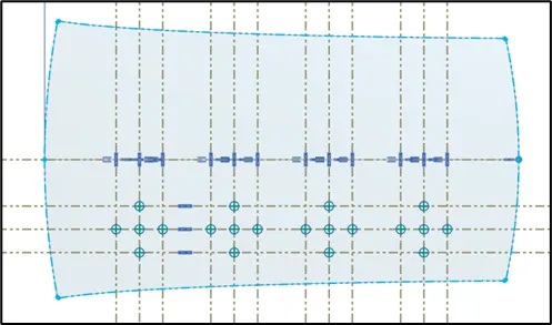
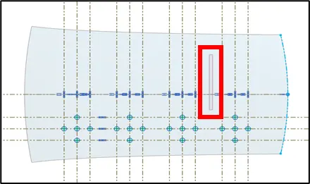
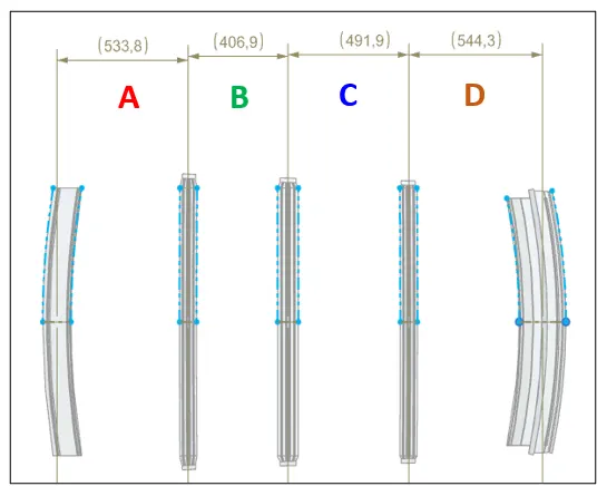
Defining the Bow Roof positions into the roof is a trial-and-error process that is validated by calculations. For this design, it was started doing a preliminary roof calculation to have an early idea about the distances at which we should position the bow roofs before to start its creation. The lines that separate regions between reinforcements were created. For this design, we planned to have 5 reinforcements (FRR + RRR + BRR 1 & 2 + CTR BRR), which means that roof calculation will be divided in 5 regions. So, Total Roof Length (without Ditch Area, only styling) available was 2,033.2 mm, so we will have 4 reinforcement lines separated by 406.64 mm (2,033.2 mm/5).
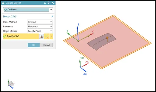
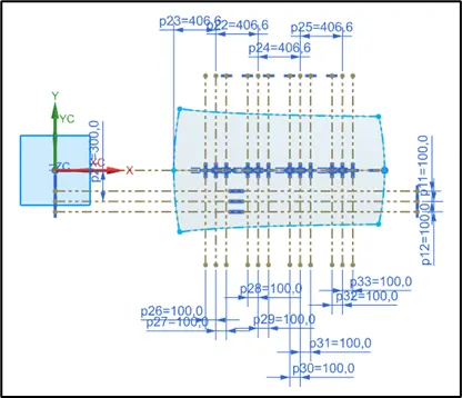
Finally, it was completed the sketch adding constraints and dimensions, creating the intersection points, and taking the midpoints between sections.
Bow Roof 1 Position
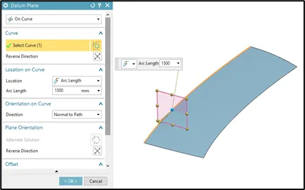
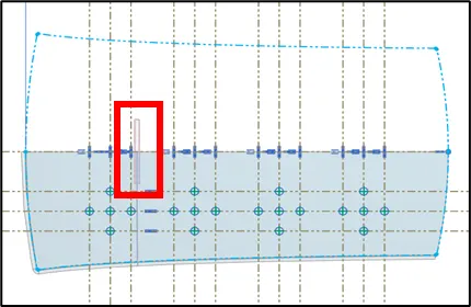
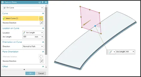
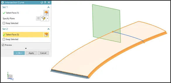
For this, it was created a Datum Plane to a distance of 1,500 mm to position this between RRR-BRR1 and BRR1-CTR RR reinforcement lines.
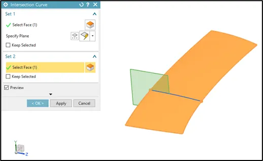
CTR Bow Roof Position
For this, it was created a Datum Plane to a distance of 1,100 mm to position this between BRR1-CTR RR and CTR RR – BRR2 reinforcement lines.
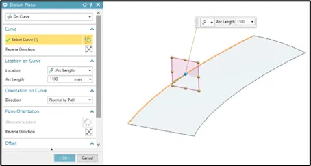
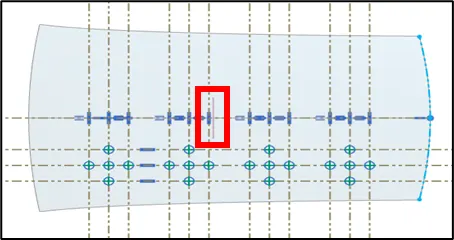
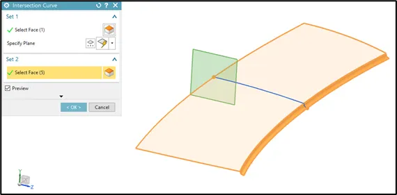
Bow Roof 2 Position
For this, it was created a Datum Plane to a distance of 600 mm to position this between CTR RR – RR2 and BRR2-RRR reinforcement lines.
Bow–Roof Prediction Formulas
Heat Distortion Criteria
Heat distortion temperature is the temperature at which the metal softens and deforms under a specific load. This study is done to check the ability of the roof to withstand high temperature with respect to the positioning of the reinforcements which contribute to increased strength. Some studies have noted issues with the outside quality when thinner outer panels are employed. The surfaces of shells bend owing to thermal strain during the painting and drying processes in addition to issues with the stamping performance. If thermal distortion is discovered, it requires a significant amount of reworking and checks for numerous parts across multiple manufacturing processes. Thermal distortion is frequently evaluated by the exterior check conducted for completed vehicles with various parts installed. Countries where the summer is high, there are chances of heat distortion due to sun heat. When the radiation of sun falls on the form of your car, then due to that heat, thermal expansion occurs and due to some thermal expansion, possibility of hanging the roof of the car is more in that area and the roof of your car becomes weak in that area.
By this calculation we verify these things whether your roof will be able to withstand in that condition or not. If that the area is not able to tolerate this condition, then we have to give better support on that area to make your roof stronger.
Prediction Formula:
W = [1.73 x 10^(-3) x L] + [1.85 x 10^(-8) x (R^2)/t] + [ 1.10x10^(-3) x l] - 2.68
where:
L = Roof Length in X-Direction [mm] (Roof dimension in 0-Y)
R = Roof curvature = 2(Rx*Ry)/(Rx+Ry)
Rx = X curvature
Ry = Y curvature
t = Roof plate thickness [mm]
l = Bow Roof Span [mm]
Judgment Condition: OK< 2.7
After creating all the reinforcements, we made some adjustments to the original sketch.
- After the design is frozen which means that you have thicken it, then create a datum plane on the top of the roof.
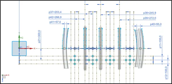
- Start a sketch in that plane and draw the lines which divide the reinforcements. Using these lines, divide the roof into different sections based on the position of these reinforcements.
- Take the midpoints between sections. For each section, get the distance between midpoints, divide it by 2 and draw a vertical line based on that half distance.
- On the plane, offset the 0Y line to 300 mm and draw the -3Y line.
- Now offset this -3Y line by 2 (100 mm above and 100 mm below).
- Offset the earlier reinforcement lines (which divide each reinforcement) by 2: 100 mm left and 100 mm right.
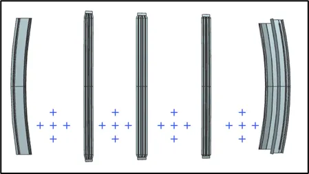
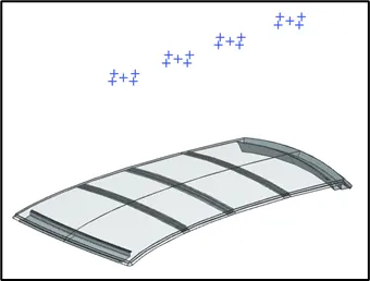
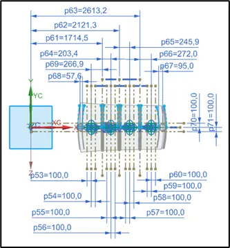
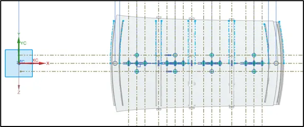
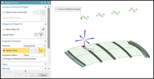
- Use the intersection of lines to create points. So, convert all these offset lines into reference lines because we do not need them on the sketch. Then, create intersection points between these lines. Finally, project the whole sketch on the roof surface. When you do that, only the plotted points will get projected because the lines and everything else are reference entities. Repeat the same for all the other places where we have reinforcement lines. Project only these 6 points plotted (3 for horizontal direction and 3 for vertical direction) up to the surface.
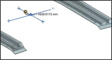
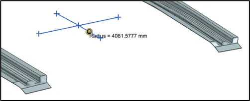
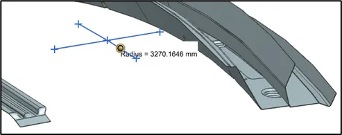
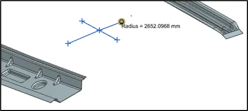
- Then you go to Curve → Arc/Circle → Three Point Arc. After the projection, you will have your points lying on the roof.
- You have to connect the 3 points in vertical direction with an arc. That will be named as ‘Rx’.
- You have to connect the 3 points in horizontal direction with an arc. That will be named as ‘Ry’.
- Then, you have to get the values for Rx and Ry.
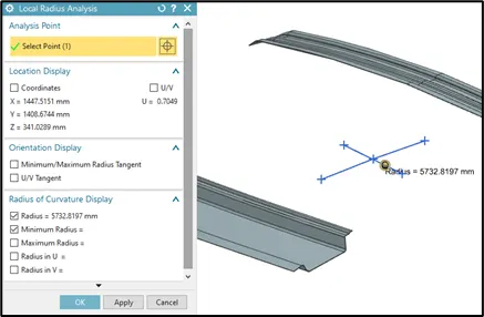
- To do that, go to Analysis → Local Radius → Click on the arc to get the Minimum Radius. Also, you can go to Menu → Analysis → Minimum Radius (or search for this command in the Command Finder).
- Also, you can go to Menu → Analysis → Minimum Radius (or search for this command in the Command Finder).
Using the real reinforcements, create points/lines at the middle of each reinforcement to separate the roof into regions. After that, take distance of each region to create midpoints between them. Finally, adjust the vertical lines at half distance between regions to give the final position.
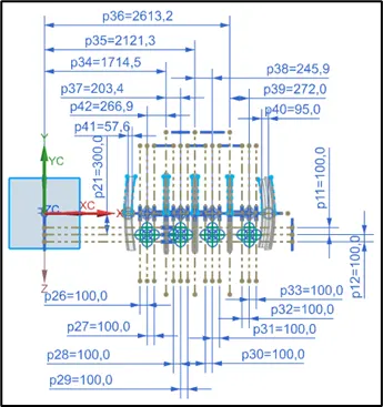
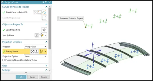
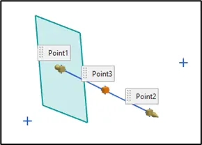
Using ‘Arc/Circle’ command, selected the ‘Three Point Arc’ option and then selected the points.
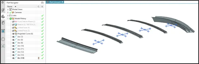
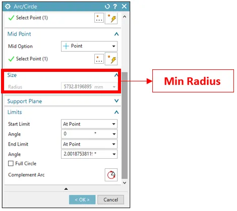
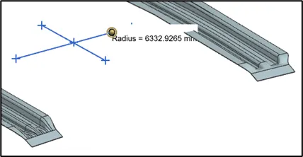
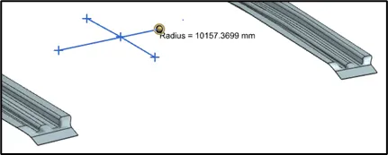
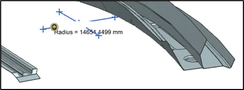
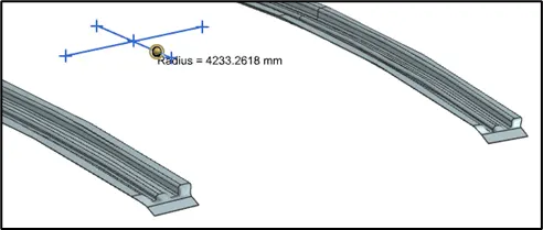
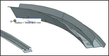
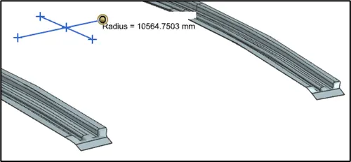
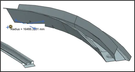
Get the Min Radius value for each arc. You can find it below in ‘Size’ section of the same ‘Arc/Circle’ dialog box. Also, another option is to measure it using the ‘Local Radius’ command.
For Rx:
For Ry:
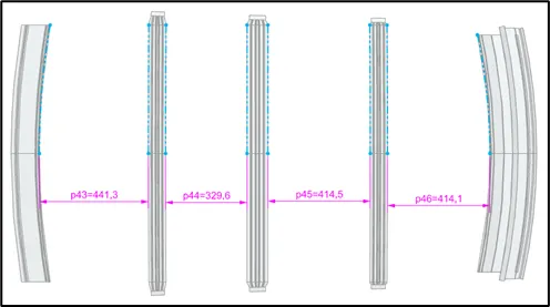
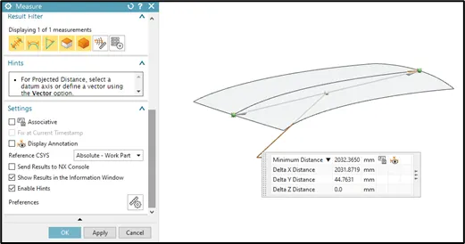
To measure the Bow Roof Span (I) needed for the Heat Distortion calculation, you can create a sketch and project Bow Roof edges to get dimensions between them. Remember that all of these dimensions should be taken in the 0-Y line.
L is nothing but the Length of the Roof in X direction (only the styling, do not take the ditch area). For clarity, you can take the 0Y line.
Making the calculations for each Roof section results in the table shown below. As shown. the Heat Distortion criteria is satisfied.

Snow Load Criteria
Snow Load Criteria study is done to check the withstand ability when the snow loads over the roof during winter in snow fall regions. This study will also analyze the roof that whether the permanent deformation occurs after removing the snow load. That it may bend but needs to be bounce back to its original position.
Roof design must pass through these calculations to ensure that it has sufficient stiffness to withstand the load due to accumulation of snow over the roof.
Formula:
Qr = [Iy x t2] / [α x s x [(Rx + Ry)/2]2 x 10-8]
where:
α = My x Lx2 x 10-12 , My = Y(Ly-Y)
t = Roof plate thickness [mm]
Ly = Distance between the front and rear roof Rails on the Vehicle along with 0Y [mm. Length of Roof panel with the center point between Roof rail Front /Rear as the front and rear reference point.
Lx = Distance between the Left and Right end of the roof on the Roof BOW [mm]. The width of the roof panel is exposed on the surface.
Y = Distance from Front Roof Rail to Roof BOW [mm]
s = L1/2 + L2/2 = Distance for which Roof BOW bears divided load [mm]
Iy = Geometrical moment of inertia of Roof BOW (Y cross-section ) [mm4]
Rx = Lateral direction curvature radius of roof panel Y cross-section on Roof BOW [mm]. Roof panel curvature Radius of the Length Lx in Front view.
Ry = Longitudinal Direction curvature radius of the Roof panel X cross-section on Roof BOW [mm]. Roof panel X curvature radius of length s in Side view
Judgment condition: Qr ≥ 3.1 and 250 ≤ s ≤ 380
BOW ROOF SECTIONS AND MOI CALCULATION
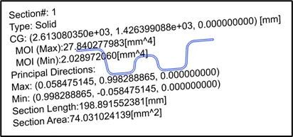
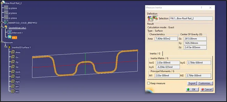
The first parameter to be calculated are the Principal Area Moments of Inertia (MOI), defined as Iy. According to the project rules, it was provided the appropriate dimensions to the Bow Roof sections in order to get adequate values that satisfies this prediction criteria.
- Length: 65-75 mm for Bow Roof 1 & 2 / 80 -90 mm for CTR Bow Roof.
- Height: 12-15 mm
Bow Roof Rail-1’s Cross Section:
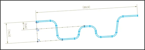
Length = 69.9 mm
Height = 14.3 mm
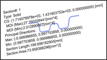
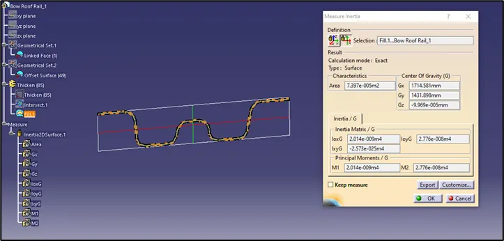
MOI = 2,014 (CATIA showing better results than NX which reflects lower values).
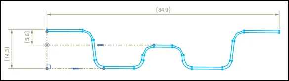
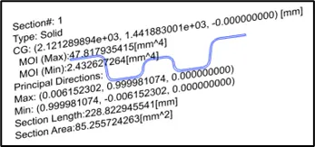
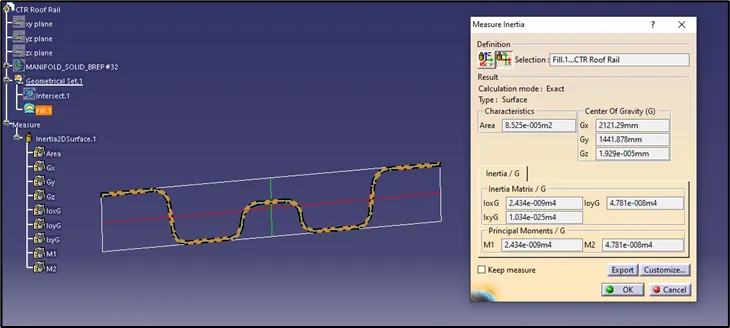
CTR Bow Roof Rail’s Cross Section:
Length = 84.9 mm
Height = 14.3 mm
MOI = 2,434 (CATIA showing better results than NX which reflects lower values).
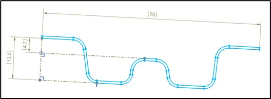
Bow Roof Rail-2’s Cross Section:
Length = 70 mm
Height = 13.5 mm
MOI = 2,030 (CATIA showing better results than NX which reflects lower values).
GETTING OTHER ROOF DIMENSIONS
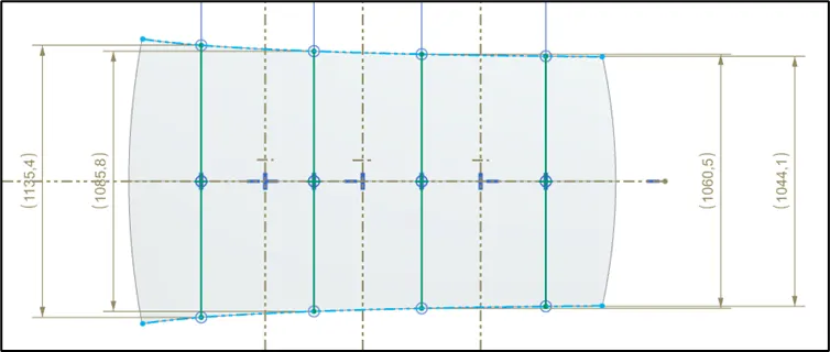
Lx: Vertical Distance between Styling Edges at midpoint between Reinforcements.
Y: Distance from Front Roof Rail to Bow Roof [mm]
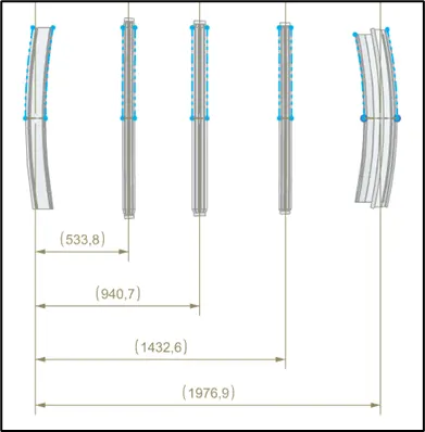
'L1' and 'L2': Distances for which Bow Roof bears divided load [mm].
Each section will have its L1 and L2.
- For section I: L1=A and L2=B.
- For section II: L1=B and L2=C.
- For section III: L1=C and L2=D.
- For section IV: L1=D and there is no L2. Leave L2 in blank because we do not have space for it.
For Snowload criteria, it was followed the same steps to get intersection points and arc radius than followed for Heat Distortion criteria. The only difference is that these points should be projected in 0-Y instead of 3-Y line.
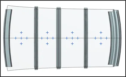
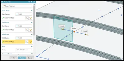

For Rx:
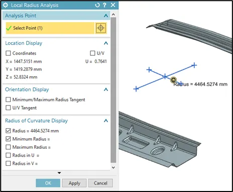
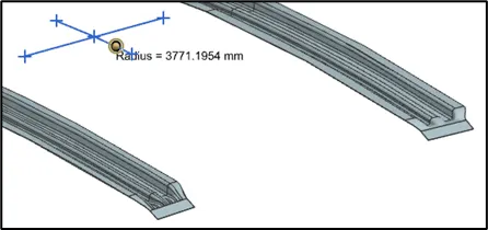
For Ry:
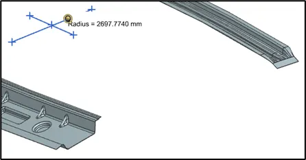
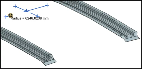

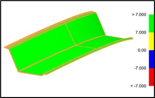
Draft Analysis
No parts can be ejected from the tool if it is having a straight 90° profile from its base surface. So, a small draft angle and a direction in which components should eject is provided to each area of the component in order to get an easy removal of the component from the tool and avoid tool wear during the manufacturing process. In addition, it helps to achieve good surface finish of the part.
Draft Analysis is a technique used to analyze whether the CAD part model is manufacturable based on the draft condition applied. During the design stage, the appropriate dimensions to the part should be provided to avoid that negative drawing angles and ensure a smooth manufacturing process. Draft Analysis is performed on components where the ejection of material happens after the material is made inside the tools. In case of Automotive Sheet Metal Manufacturing, the blank sheet metal after turning into automotive panels like Hood, Fender, Roof, Side Doors, Back Doors, etc. need to be removed from Panel Dies. If a considerable amount of draft angle is not provided, the component removal from the tool will be difficult.
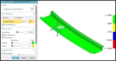
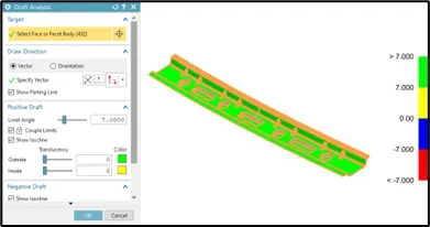
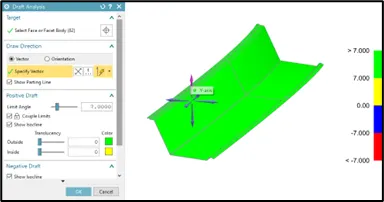
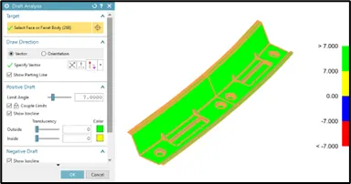
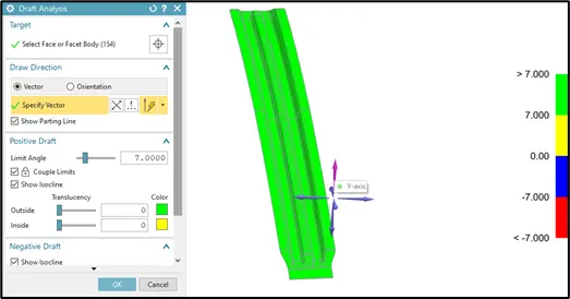
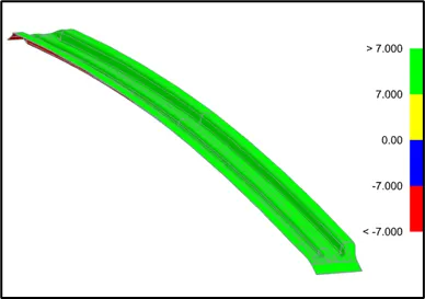
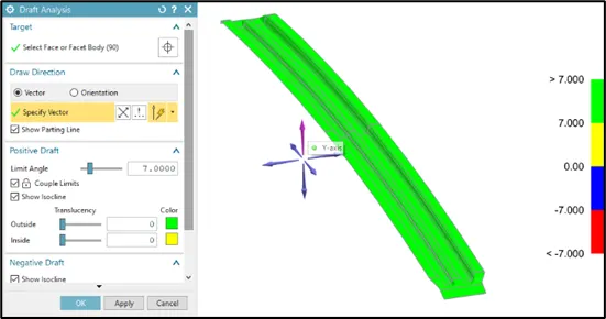
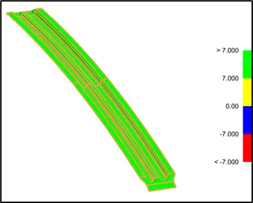
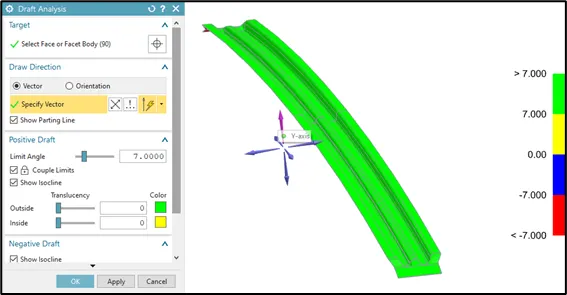
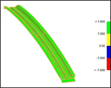
According to the project rules, the appropriate dimension must by more than 7° for a positive draft. So, the Draft Angle simulation results should be interpreted as follows:
- Green – All the region that is green is supposed to be Positive. It covers all the regions that are more than 7°.
- Yellow, Blue, or Red – Regions that are considered Negative.
- Yellow = Between 0 and 5°. Sometimes, in critical situations, it can be accepted.
- Blue = Between 0 and -5°. It is considered ‘Not Accepted’.
- Red = Les than -5°. Definitively considered ‘Not Accepted’.
Front Roof Rail
Rear Roof Rail
Inner Rear Roof Rail
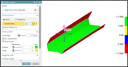
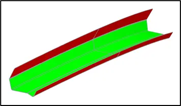
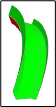
The rear ditch area flange is bending inwards. This is because it is done in 2 operations: Deep drawing followed by bending operation. So, the red portion shown there is not an issue since that operation is bending and not deep drawing. That portion can be obtained via bending process as well. Even if we are going with stamping process, that portion can be obtained with another die with negative draft, designed for that specific portion.
Outer Rear Roof Rail
Bow Roof 1
CTR Bow Roof
Bow Roof 2
REFERENCES
- Mohammed A. Omar, ‘The Automotive Body Manufacturing Systems and Processes’, Wiley (2011).
- Boljanovic, Vukota, ‘Sheet Metal Forming Processes and Die Design’, Industrial Press, Inc., 2nd Edition (2014).