Hood design-Week 2
HOOD DESIGN CHALLENGE
Theoretical Background
Hood and Components
The Hood (also called Bonnet) of a car is considered as the frontal BIW enclosure component. The hood is an opening body panel that covers the engine in a front-engine vehicle compartment. It’s critical component because:
- Frontal Crash
- Pedestrian safety requirements.
- Dissipates the energy outside the car body rather than sending it inside the car body.
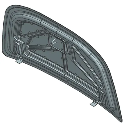
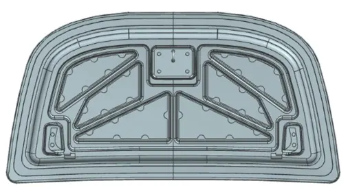
The hood is also considered as another type of door un a vehicle as it consists of an outer panel and inner panel. The inner panel provides the strength while the outer panel functions as the metal cover. The Hood or the Bonnet consists of the following parts:
- Hood outer panel
- Hood inner panel
- Latch and Striker re-enforcement
- Hinge re-enforcement
- Gas stays re-enforcement
Hood Outer Panel
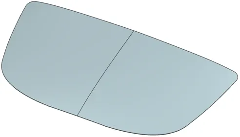
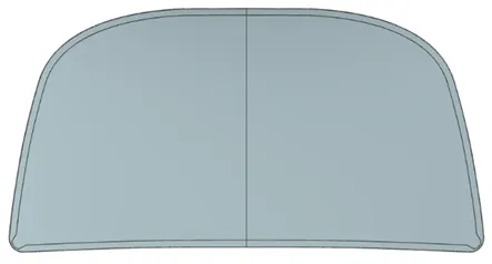
Outer panels are the aesthetic elements of a car. It is the styling team who provides the skin for the outer panel. The shape, position and size of the hood should satisfy the safety norms. So, while designing the hood we should give more importance to pedestrian safety. The outer panel is attached to the inner panel by hemming. So, it is necessary to provide required hemming flange and reliefs for the hemming operation. We also provide mastic sealants between outer panel and inner panel to reduce vibration.
Hood Inner Panel
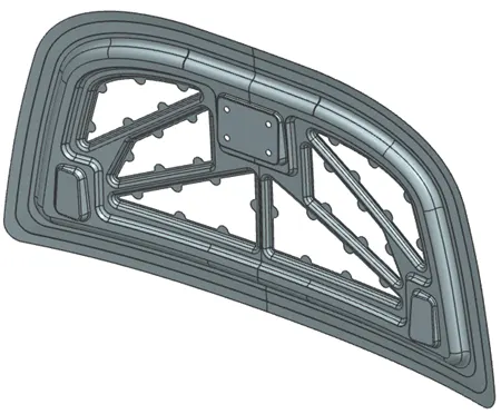
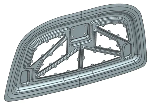
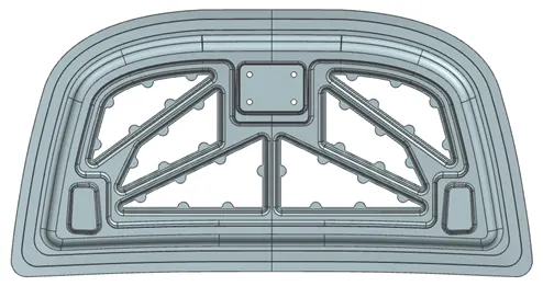
Inner panel is the part found into the vehicle compartment that gives strength and rigidity to the outer panel.
Hinge Assembly
Striker
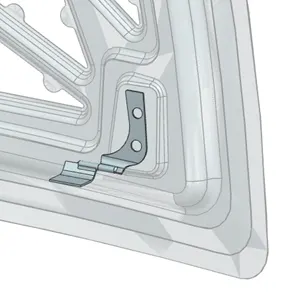
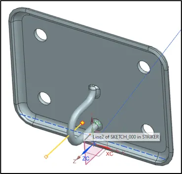
The striker is the point that locks the hood when it’s needed to keep it closed. Whenever that the hood is opened, there should be a gap between the hood tip and the striker. In cases in which the striker is unlocked, there is a second latch available outside the car.
Reinforcements
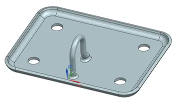
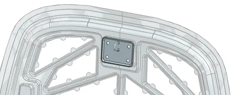
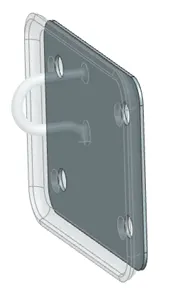
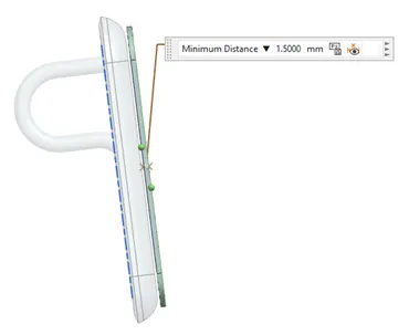
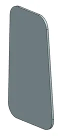
Reinforcements are provided according to the design requirements. Mainly it is provided at the hinge and latch regions to improve the strength locally. Usually thickness of reinforcements will be higher than that of the inner panels and the value varies according to cost and requirement. Typically, reinforcements are parts of thickness in a range between 1.5 mm to 2 mm provided to improve the strength of the sheet locally due to strength loss by mounting devices like hinges or striker. When hinge is fixed to the sheet the strength of the sheet reduces locally because you are adding weight. To compensate for the loss of this strength, a reinforcement is provided. Always that weight is added to a material, it produces strength is lost locally in that area. The reinforcements are mounted intentionally to help to compensate that local loss of strength due to addition of certain devices. In summary, reinforcement is material added to improve strength.
After the development of the entire inner panel for the hood, it is needed to develop some additional necessary re-enforcements for the Latch striker and the hinges. The re-enforcements are attached to the hood inner panel using the spot-welding method. The positions to be spot-welded are provided by the design team.
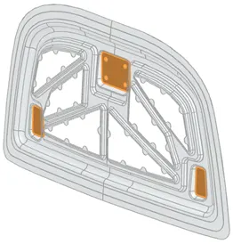
In what area of the Inner Panel should the reinforcements be added?
- Latch and Striker – In the central area of the Inner Panel where the Latch and Striker are mounted.
- Hinge – In the corners where the Hinges are mounted. The Hood motion would not be possible without hinges. To get opening and closure motions, it’s required hinges are activated, as well as an axis across the motion will be performed.
In general, reinforcements are added in the whole hood. The inner panel for itself is used as a large reinforcement for the Outer Panel.
Striker Reinforcement
Hinge Reinforcement
Designing the Hood in NX
Master Inputs
Hood Dimensions
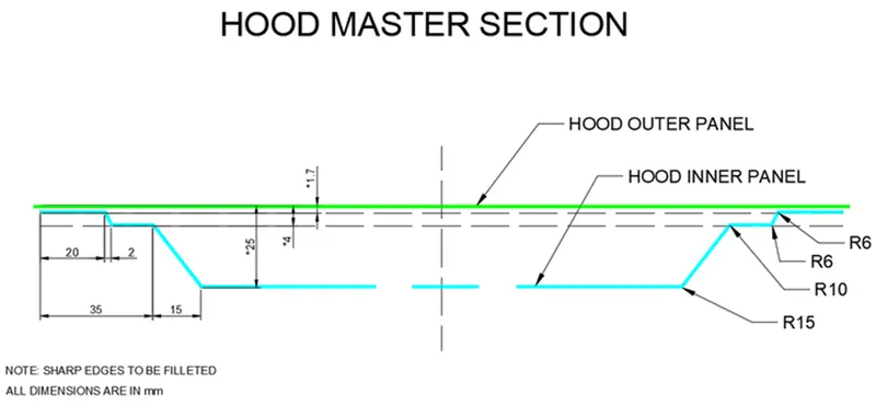
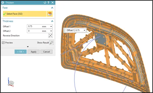
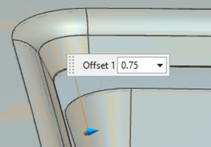
- Outer Panel Thickness = 0.75mm
- Inner Panel Thickness = 0.75mm
- Reinforcement Thickness = 1.5mm
Hemming Requirements:
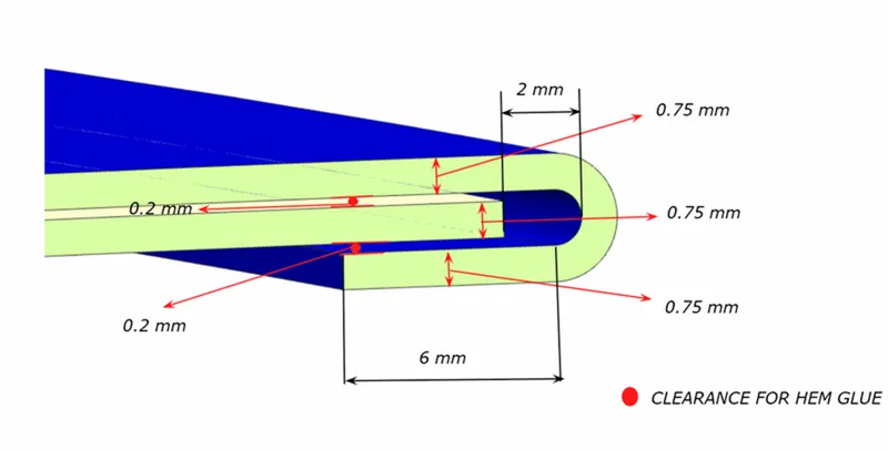
Relief Rear & Front Sections:
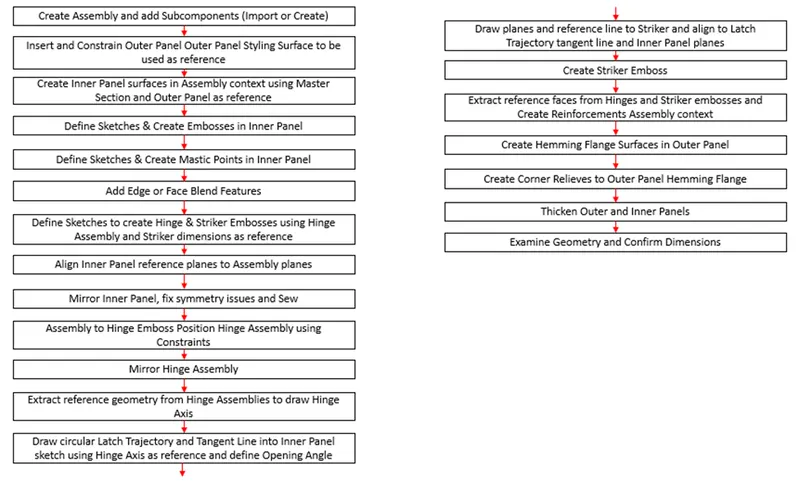
Flow Chart of Hood Design Process in NX
The flow chart below summarized all the steps followed during Hood development in NX.
Design Parameters Used in Hood Development
In summary, the most important engineering parameters considered for Hood design were:
Emboss Definitions
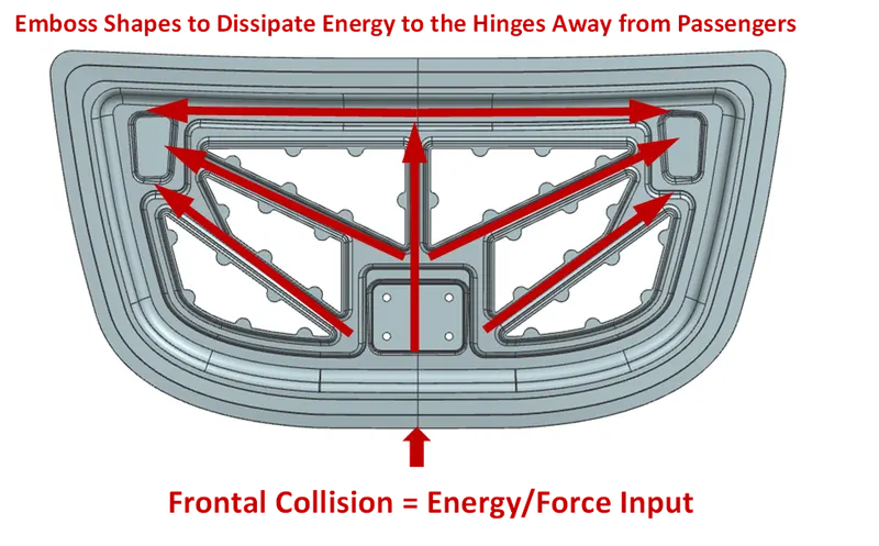
The most significant design intention for a hood is for the frontal collision requirement. It means that now that the hood crushes in a collision, the force gets into the hood directly and it should be designed to dissipate forces in the upward direction up to the hard points and deflect that force away to the passengers. The hood design engineer should be capable to come up with ideas about how to dissipate these forces outside the car as far as possible. The component is designed to divert the force away from the passengers into the hinges. One way to achieve this is creating structures like embosses in such a way that the force is diverted to the hinges. There are no specific criteria for emboss design. However, the best practices propose Y or V structures that provide ways to dissipate energy appropriately.
Therefore, this design includes the next features:
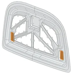
- Multilevel embosses to increase the stiffness of the inner panel.
- Shape and size of the embosses that makes sure that the direction of the force distribution from frontal collision should be always distributed away from the passengers.
- Embosses with drawing angles about 80º to ensure tooling extraction.
The image below shows how the pattern of embosses will deviate force in such a way that it will be diverted to either side of the car.
Design of Flat End Embosses to mount Hinge and Striker
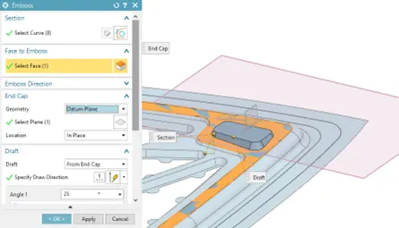
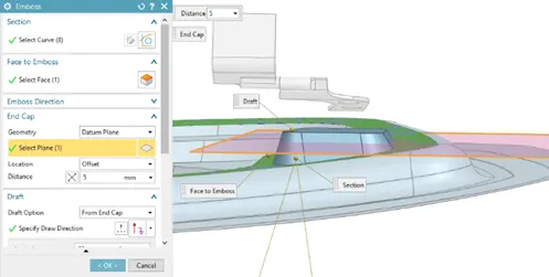
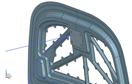
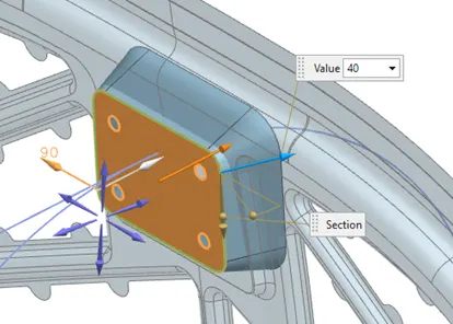
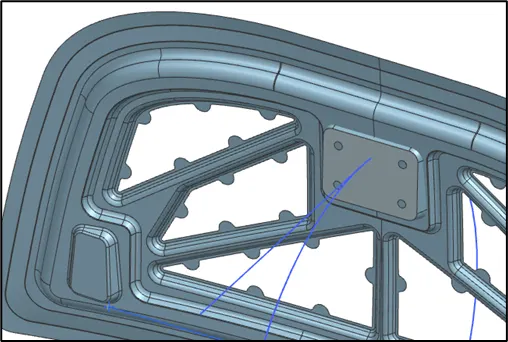
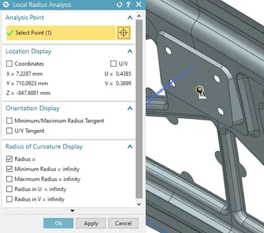
Because of hood inner panel surfaces present certain degree of curvature, it will make difficult to mount devices with flat surfaces. It was considered the creation of flat surfaces for the embosses to place appropriately the Hinge and Striker devices. To do that, it was used Datum Plane as flat reference for emboss creation.
Hinge Embosses
Striker Emboss
Mastic Data
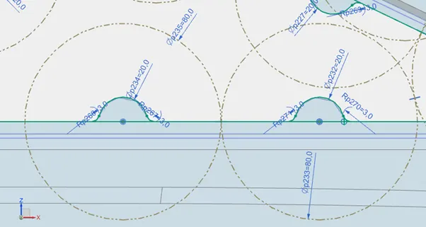
Mastic sealant is an elastic compound (gel-type substance) that behaves like a rubber and is applied between the inner and outer panels of the Hood. The mastic points are defined on the hood inner panel where the hood can easily deform. They help the hood outer panel to come back to its original shape after it gets deformed. The mastic effects have a range (influence area) of 80 mm diameter. The mastic point will reduce the NVH for the radius of 80mm. So, providing several mastic points on the center area of the hood will increase the performance of the car.
The benefits of Mastics are:
- Improved NVH factor
- Increased strength locally and increase structural integrity of the assembly.
- Effective Joining method without compromising the aesthetic factor of the Vehicle.
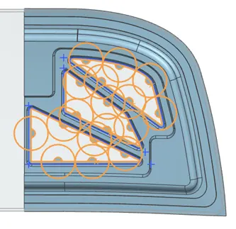
There are cutouts on the inner panel emboss that represent Mastic positions. The gap between the inner panel emboss on which Mastics are to be placed (cutouts created) and the Outer Panel should be 5mm since that is the optimum gap for Mastics to spread.
For this design was considered the recommended influence area of 80 mm diameter to separate adjacent mastic points (as shown in the image below).
In summary, Hood design involves 3 correlated parameters:

Hood Opening Angle
This is a parameter defined in design early stages and should be determined because it affects other parameter like Support Rod length and Lock Striker location. The limit values depend on each region and market. Eventhe same car model in different regions could have different opening angle values.
- India – Average Height is 5.5 ft (1.68 m).
- Europe – Average Height is 6 ft (1.83 m). Opening angle for this market is higher.
Latch Trajectory
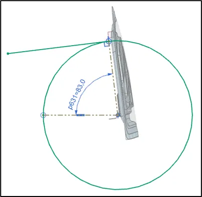
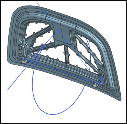
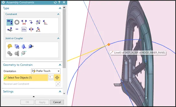
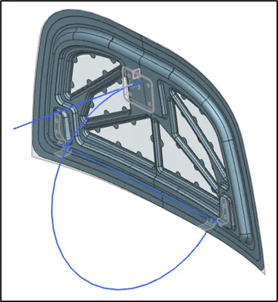
The other major function of the hood is the opening and closing of hood. This is done with the help of the latch and striker. Latch is a part where the striker pin gets locked. Latch trajectory is the path in which the latch moves. Latch trajectory is given by the circle drawn from the hinge axis point. Hinge axis point is the center point of the hinge axis. First, we can fix either the latch or the hinge. If we have fixed the hinge position, then we should plot the trajectory circle for the latch. For proper mating condition the striker axis through the tip of the striker should be tangential to the latch trajectory. Only if the hinge position is correct, the lock will get aligned to the hole which enables locking. Similarly, we need to align the striker provided with the trajectory or path (circle) created by using the hinge line as center.
Another design requirement considered in this hood design is the adequate position of the striker device to ensure a good alignment and the correct hood closure. A sketch was created in Inner Panel to constrain the tangent line in latch trajectory to striker center line.
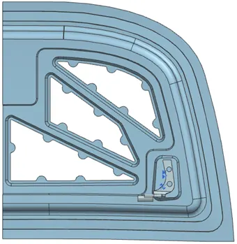
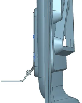
Now, using the hinge axis as the center, we draw a big circle to the position where we need the latch to be placed. Then, we draw a tangent line to the circle at that point and place the latch in that region. This circle represents the represents the path of Hood Opening Enclosing. If the striker remains exactly perpendicular to the path, it means that the hinges positions are correct. On the contrary, the hinges should be moved either inside or outside to achieve that the striker stays in perpendicular position.
Hinge Axis
The hinges are elements that allow Hood rotation. These are typically mounted within the engine compartment, one in right side and another one in left side. Both hinges share same axis named Hinge Axis. The correct positioning of this axis is extremely important for hood design because it directly affects to the appropriate hood closure. To position the latch and striker effectively, we position the hinge and draw the hinge axis.
Latch Point
This is a point that is correlated to the Hinge Axis. If one is displaced, therefore, the another one also will do to achieve the perpendicularity of the striker. Also, this correlation encourages the correct positioning of the latch. The latch is located into the engine compartment, but if the perpendicularity is not kept between striker and circular path, therefore when the striker reaches the latch, it will not close adequately.
Hemming
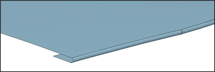
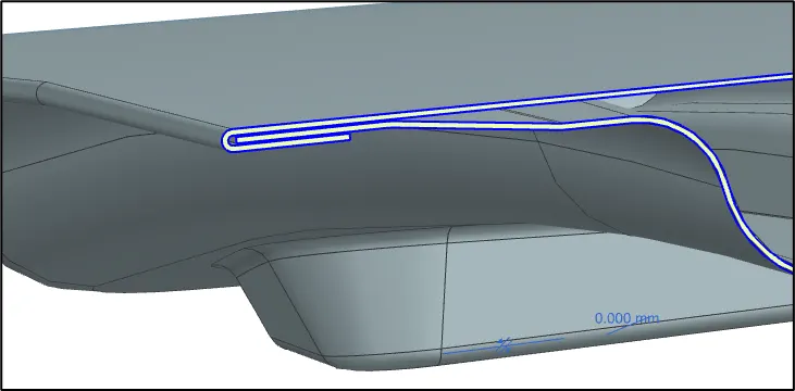
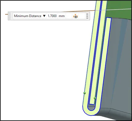
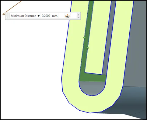
Hemming is a forming operation in which the edges of the sheet are folded or folded over another part to connect parts together achieving a tight fit to improve the appearance of a part and to reinforce part edges. This is the process used to join both the outer and inner panels together. The hemming process roles and wraps the hood outer panel around the inner panel and holds it tightly together.
The design intention for this Hood design was fulfulled achieving the next he requirements:
- Outer Race to Inner Panel Gap = 1.7 mm
- Outer Panel Lower Surface to Inner Panel Upper Surface = 0.2 mm.
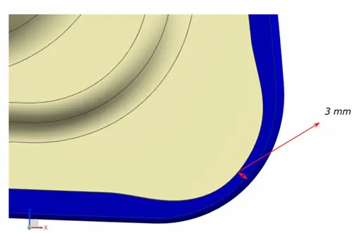
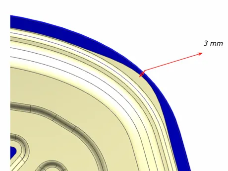
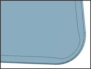
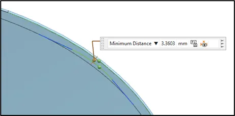
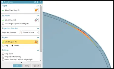
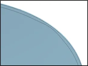
Hem Corner Reliefs
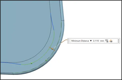
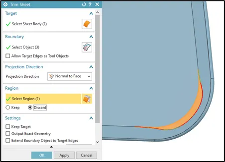
When hem joint process is carried out, corner relaxation should be considered. The corner relief process is based on the rolling process, but in this, rollers are positioned in the different hood corners. Each roller will pass over the sheet metal edges to lock it against the inners panel. This process will be repeated 2 or 3 times to improve the hem closure each time up to get a constant and perfect closure. The reason why different rollers are used is because only one is not enough to roll over all the regions. Several rollers can work in parallel to save time and complete the process. The relief is achieved making the roller do not pass completely over the corner. When the ball is close to the corner, it does not press the panel completely, but it gets apart a little to apply less pressure.
For this design, the intended 3 mm relief corners were included.
Relief Rear Section:
Relief Front Section:
Pedestrian Head Injury Criteria
Inlaid Hood
In Inlaid Hood the end point of the car lies on Fender.
Wrap Around Hood
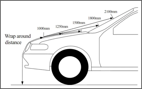
When endpoint of car lies on hood then it is called wraparound hood. Wrap Around Distance (WAD) is the trace of the points received on the front structure when one end of flexible tape of required length held at ground level and other end in contact with the front structure.
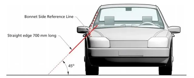
Side Reference Line - It means the trace of the highest contact point between straight edge inclined at an angle of 45 degree and side of the vehicle.
Side Reference Line
It means the trace of the highest contact point between straight edge inclined at angle of 45º and side of the vehicle. It is a 45º line with respect to ground that extends to touch tangently the car. This line is used as reference to understand ther parameters like:
- Head Impact
- Pedestrian Euro-NCAP Assessment
Wrap Around Distance (WAD)
WAD means the trace of the points received on the front structure, when one end of flexible tape of required length held at ground reference level and other end in contact with the front structure. WAD depends on:
- Hood size.
- Car length.
The designer should define where Lateral and WAD reference lines (or planes) will be located when making the styling. These two parameters determine how much área I count for the design.
- If line is located inside, it means that it lies on the Hood. It means that the car has Wrap Around Hood, so that WAD will be shorter, and head impact zone will be more extensive. If hood dimensions are larger, so that hood impact area will increase.
- If line is located outside, it means that it lies on the Fender. It means that the car has Inlaid Hood, so that WAD will be longer, and head impact zone will be less extensive. If hood dimensions are larger, so that hood impact area will reduce.
Pedestrian Head Impact and Injury
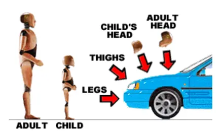
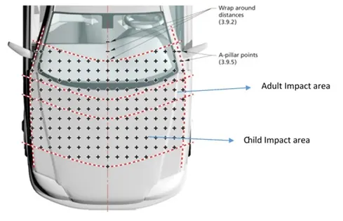
When pedestrian collision takes place, it will hit its head against the hood. This hitting zone define 2 categories:
- Child Head Impact – WAD: 1000-1500
- Adult Head Impact – WAD: 1500-2100
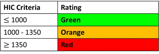
HIC (Head Injury Criteria)
This is the rating that is received from a Hood Engineer. Therefore, it is a critical parameter that affect how a car model will be assessed in terms of safety.

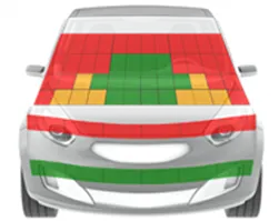
Euro-NCAP 5 Star Rating Criteria
A new car model requires of approving these rigorous safety assessments to improve its rating.


Deformable Brackets
This kind of brackets are easy to be deformed during a collision due to weaker cross sections and their purpose is to reduce the force exerted over the human when impact occurs. The objective is that the designer adds this kind of bracket to increase the green region assessed by Euro-NCAP.