Roof Design
ROOOF CHALLENGE
AIM
To create an assembly by developing the essential flanges for The outer roof and create the reinforcements.
ROOF DEFINITION
An automobile roof or car top is the portion of an automobile that sits above the passenger compartment, protecting the vehicle occupants from sun,wind,rain,and other external elements. because the earliest automobiles were designed in an era of horse-drawn carriages,early automobile roofs used similar materials and design.
In later years many variations on the autombile roof developed, they are
TYPES IN ROOF
a) CONVERTIBLE ROOF
A convertible or cabriolet roof is a passanger car that can be driven without a roof in place. The methods of retracting and storing the roof vary among eras and manufacturers.A convertible car's design allows an open-air driving experience, with the ability to provide a roof when required. A potential drawback of convertible roofs their reduced structural rigidity ( requiring significant engineering and modification to counteract the effects of removing a car's roof).
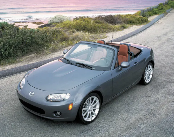
FIG:- CONVERTIBLE ROOF
b) HARDTOP ROOF
A hardtop is a rigid form of a autombile roof, which for modern cars is typically constructed from metal. A hardtop roof can be either fixed (i.e not removable), detachable for separate storing or retractable within the vehicle itself.
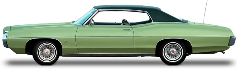
FIG:- HARDTOP ROOF
c) SUNROOF
A sunroof is a movable panel that opens to uncover a window in an automobile roof,allowing light and fresh air eneter the passenger compartment. Sunroofs can be manually operated or motor driven,and are availabe in many shapes,sizes and styles. While the term "sunroof" is now used to genercially to describe any glass panel in the roof, the term "moonroof" was historically used to describe stationary glass panes rigidly mounted in the roof panel over the passenger compartment.A moonroof has g glass panel that is transparent and usually tinted. Previous terms include sunshine roof, sliding head and sliding roof.
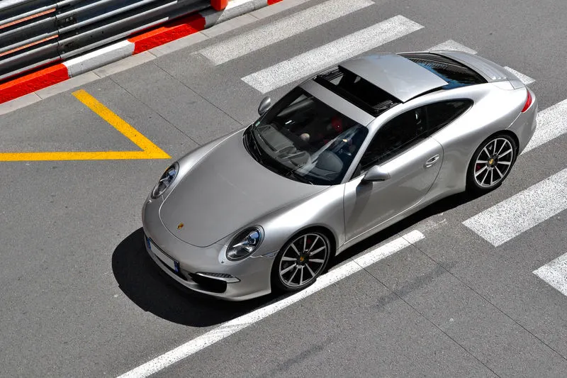
FIG:- SUNROOF
d) T-BAR ROOF
A T-top (UK: T-BAR) is an automobile roof with a removable panel on each side of the rigid bar running from the center of one structural bar between pillars to the center of the next structural bar.The panels of a traditional T-top are usually made of auto grade safety glass.
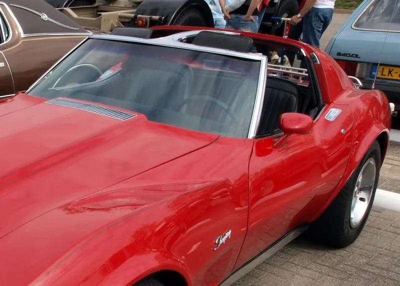
FIG:- T-bar ROOF
e) TARGA TOP ROOF
Targa top , or targa for short , is a semi-convertible car body with a removal roof section and a full width roll bar behind the sheets. The rear window is normally fixedm but on some targa models, it is a reemovable plastic foldable window, making convertible-typr vehicle. Any piece of normally fixed metal or trim which rises up from onse side, over the roof and down the other side is sometimes called a targa band , targa bar, or a wrapover band. Targa tops are different from T-tops , which have a solid, non-removable bar running between the top of the windscreen and the rear roll bar, and generally have two separate roof panels above the seats that fit between the window and central t-bar.
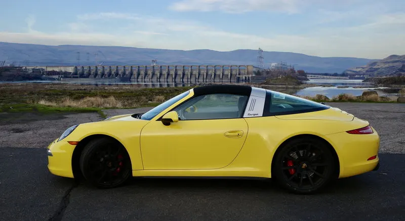
FIG:- TARGA TOP ROOF
f) VINYL ROOF
This covering was originally designed to give the appearance of a convertible models with fixed roof and eventually evolved ino a styling statement in its own right. Vinyl roofs were most popular i the American market, and they are considered one of the period hallmarks of the 1970s domestic cars. Vinyl roofs were also popular on European-(especially UK) and Japanese-built cars during the 19070s, and tended to be applied to suporting or luxury trim versions of standard saloon (sedan) models.
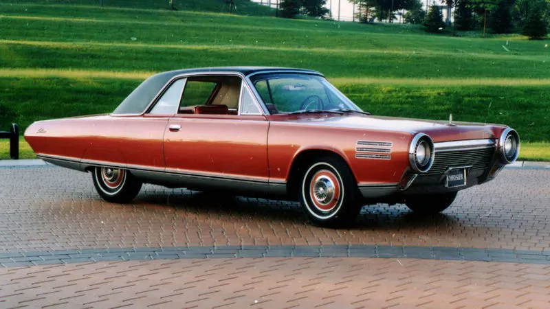
FIG:- VINYL ROOF
COMPONENTS OF ROOF
a) Front roof rail
b) Bow roof
c) Center roof
d) Rear roof rail
a)FRONT ROOF RAIL
Front roof rail joints the windshield class to the outer side of the car body. At the starting edge from the outer surface its have the 3degree inclination to maintain the 21.5mm flange length. According to the windshield class thickness, rubber paste thickness (under the windshield glass) and the sealent ( behind the glass) the flange length is need to maintain.Acccording to the visibility criteria the height of the front roof rail is fixed. The length of the roof rail is depends on the head room clearance of the driver.
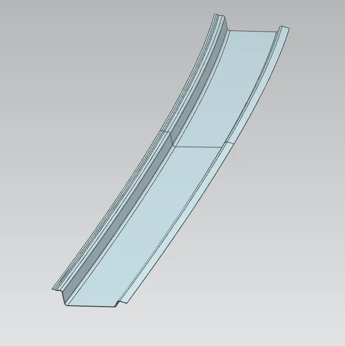
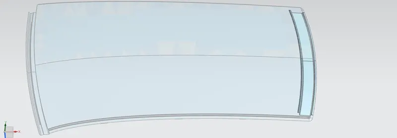
FIG:- FRON ROOF RAIL
b) REAR ROOF RAIL
Back door of the car is mounting on this rail. The structural design of the roof is changes according to the way of back door opening and closing.The upper edge of the roof rail is joined to the roof surface by using maestic sealents. The lower edge of the roof rail is joined by the way of spot welding to the outer surface . It have the 10mm clearance for spot welding.
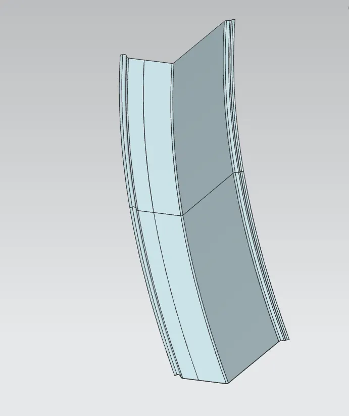
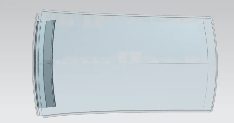
FIG:- REAR ROOF RAIL
c)BOW ROOF
Bow roof gives the additional strength to the roof. According to the length and curvature of the roof the number of boroof will be change. It have the length of 65-75mm and its joined to thr roof surface by maestic sealents.
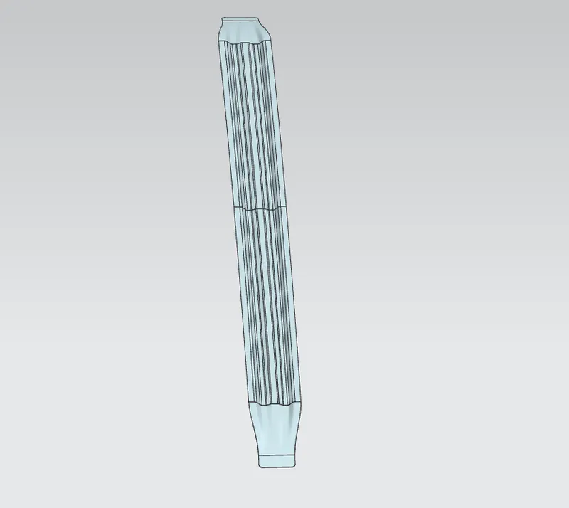
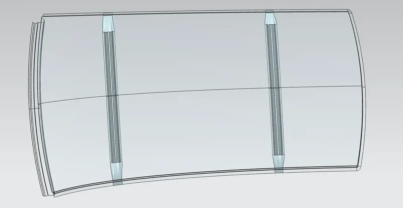
FIG:- BOW ROOF
d) CENTER ROOF
Center roof rail also gives the additional strength to the roof . If the roof have better curvature no need bow roof only the center roof is enough.Its have the length of 80-90mm. According to the bowroof length it little bit high and its also joined by maestic sealents for better roof surface.
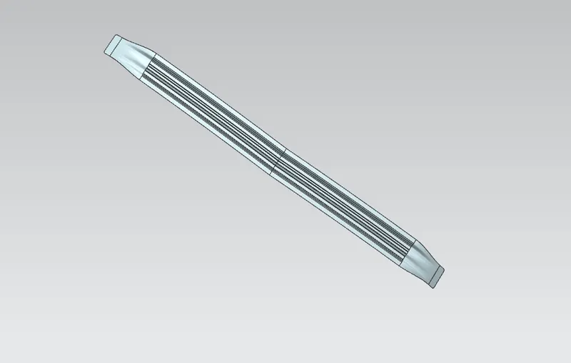
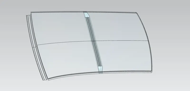
FIG:- CENTER ROOF
DRAFT ANALYSIS
a) ROOF SURFACE
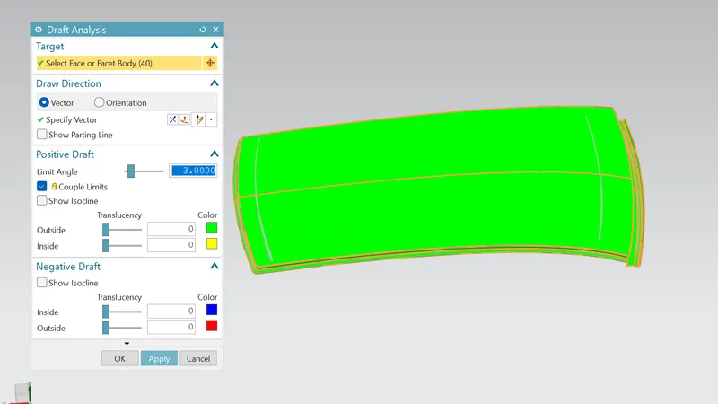
FIG:- DRAFT ANALYSIS ON ROOF
b) FRONT ROOF RAIL
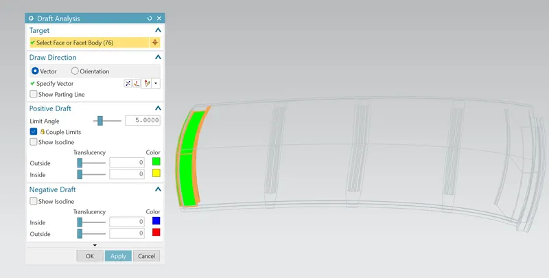
FIG:- DRAFT ANALYSIS ON FRONT ROOF RAIL
c) REAR ROOF RAIL
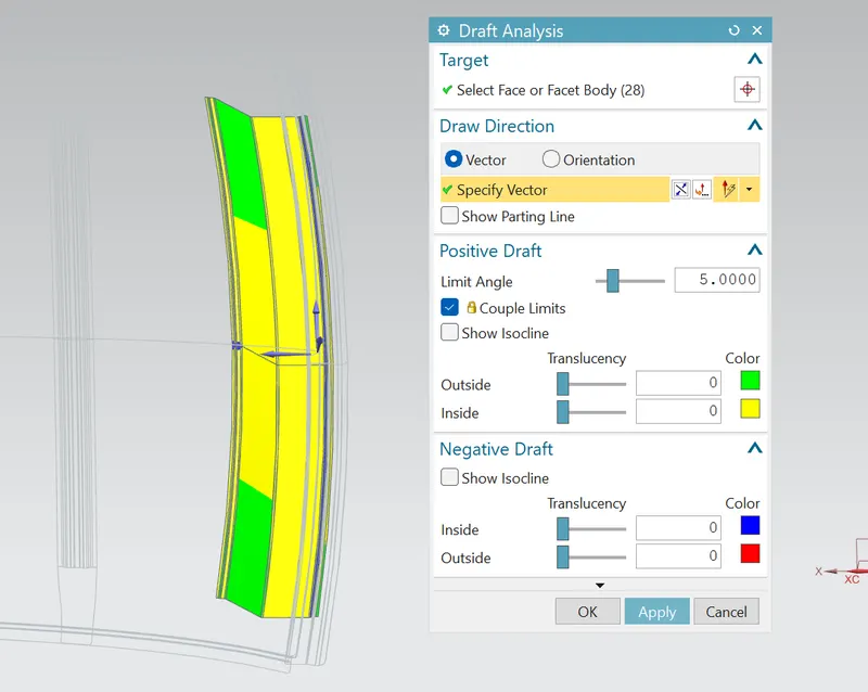
FIG:- DRAFT ANALYSIS ON REAR ROOF
d) BOW ROOF
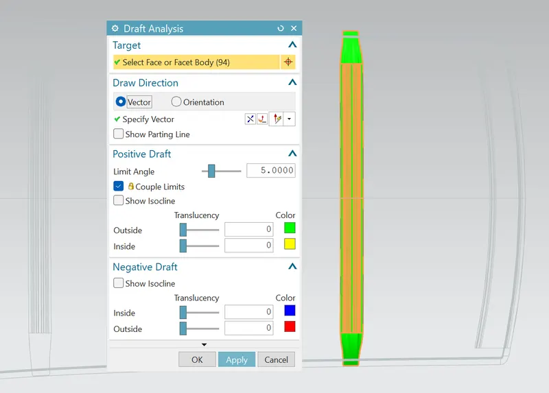
FIG:- DRAFT ANALTSIS ON BOWROOF
e) DRAFT ANALYSIS ON CENTER ROOF
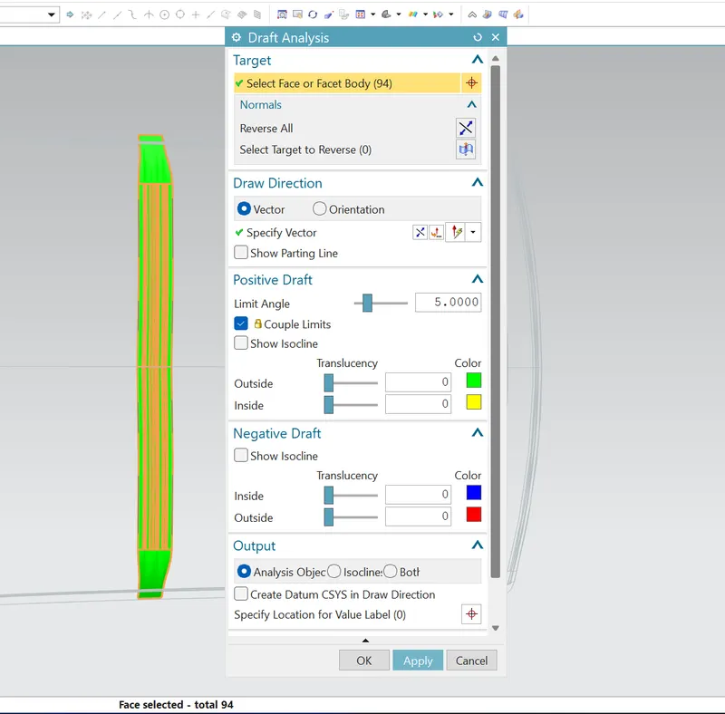
FG:- DRAFT ANALYSIS ON CENTER ROOF
ROOF CALCULATIONS
a) BOW-ROOF PREDICTION CONDITIONS
FORMULA
W = [1.73* 10^(-3)*L] + [ 1.85*10^(-8) * (R^2)/t] + [1.10*10^(-3)*l] - 2.68
Where,
L = ROOF LENGTH IN X DIRECTION [mm] ( Roof dimension in O-Y)
R= ROOF CURVATURE
R= 2(Rx*Ry)/(Rx+Ry)
Rx= X Curvature
Ry= Y Curvature
t = roof plate thickness [mm]
l = bow roof span [mm]
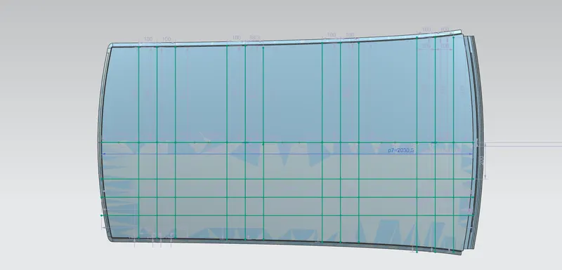
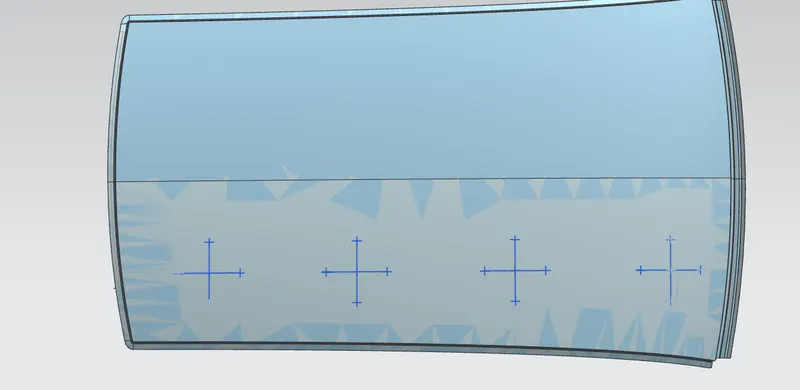
FIG :- SKETCHING FOR BOWROOF PREDICTION
BOWROOF PREDICTION TABULATION ( JUDGEMENT CONDITION OK<2.7)
| S.NO | BOW's | Rx | Ry | R | l | L | t | W | RESULT |
| 1 | FRONT&FIRST | 6449 | 6968 | 6698.46 | 414.20 | 2030.5 | 0.75 | 2.38 | OK |
| 2 | FIRST&CENTER | 3093 | 10367 | 4764.50 | 404.63 | 2030.5 | 0.75 | 1.83 | OK |
| 3 | CENTER&SECOND | 8070 |
55382 |
14087.27 | 450.8 | 2030.5 | 0.75 | 6.21 | NOT OK |
| 4 | SECOND&REAR | 3056 | 2016 | 2429.37 | 432.9 | 2030.5 | 0.75 | 1.45 | OK |
( According to the judgement of W<2.7, it satisfies only at the three posityions. At the gap between center roof to the second bow roof the judgement not satisfied, here we need to add the additional supports to improve the roof strength and remodeling this section at required position.)
b) SNOW LOAD PREDICTION CONDITION
FORMULA TO BE USED,
Qr=[Iy*t^2]/[@*s*[(Rx+Ry)/2]^2*10^-8]
where,
@=My*Lx^2*10^-12, My=(Ly-y)
t = roog plate thickness [mm]
Ly= distance between the front and rear roof rails on the vehicle along with 0Y [mm]
Lx= distance between the left and right end of the roof on the roof bow[mm]
Y= distance from front roof rail to roof bow [mm]
S= distance for which roof bow bears divided load [mm]
S= L1/2+L2/2
Iy= Geometrical moment of inertia of roof bow (Y cross section)[mm^4]
Rx= Lareral direction curvature radius of roof panel Y cross-section on roof bow [mm]
roof panel curvature radius of the length Lx in front view
Ry= Longitudinal direction curvature radius of the roof panel X cross-section on roof bow [mm]
roof panlel X curvature radius of length s in side view
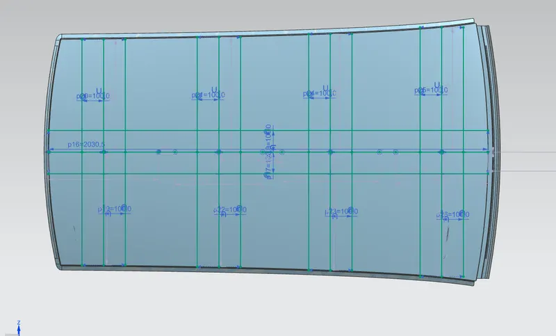
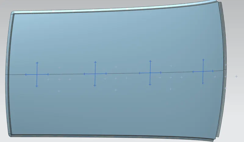
FIG:- SKETCHING FOR SNOW LAOD PREDICTION
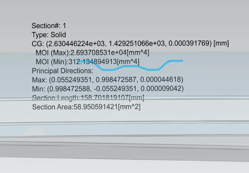
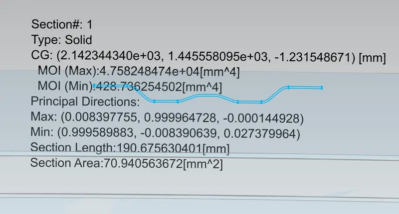
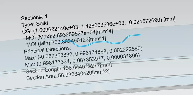
FIG:- MOMENT OF INERTIA OF BOWROOFS
SNOW LOAD PREDICTION TABULATION ( JUDGEMENT CONDITION Qr greater than or equal to 3.1)
| S.NO | BOW's | Iy (mm^4) | @ | Lx | Ly | Y | s | Rx | Ry | t | Qr | determination (Qr) |
| 1 | FRONT&FIRST | 312.13 | 0.0017 | 1040 | 2037.5 | 509.6 | 457 | 3910.35 | 16948.25 | 0.75 | 270.25 | OK |
| 2 | FIRST@CTR | 428.73 | 0.0018 | 1060 | 2037.5 | 405.4 | 428.2 | 4253.70 | 10800.75 | 0.75 | 716.45 | OK |
| 3 | CTR&SECOND | 303.89 | 0.0018 | 1090 | 2037.5 | 451 | 438.5 | 3756.93 | 5878.60 | 0.75 | 284.4 | OK |
| 4 | SECOND&REAR | 0.0021 | 1150 | 2037.5 | 426.2 | 4870.90 | 2166.97 | 0.75 |
MANUFACTURING STEPS IN CAR ROOF
STEP 1 : BLANKING
Manufacturesrs use blanking to punch pieces in specific shapes from sheets or strips of raw material. The punched out piece is called the "blank", hence the term is called "blanking". Blanking is most often performed with tools made from hardened steel or carbide, which work on metals like aluminium, carbon steel,stainless steel and even plastic.
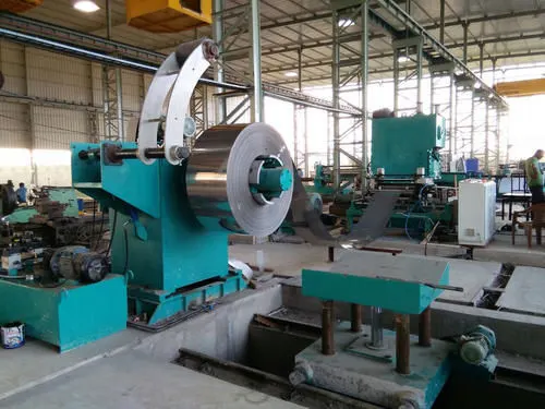
FIG:- BLANKING
STEP2: STRETCH FORMING
Stretch forming is a forming process that involves metal wherein a piece of metal is stretched and bent. This process is usually done on stretch press wherein the metal is gripped at the edges so that i cannot break loose. The metal is held together by gripping jaws that are attached to a carriage.
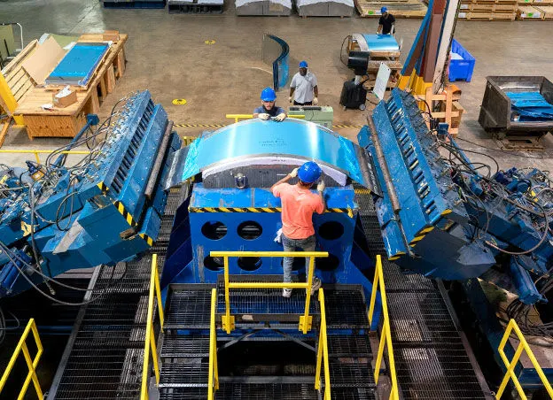
FIG :- STRETCH FORMING
STEP 3 : TRIMMING AND PUNCHING
Trimming is basically a process in which unwanted, excess or irregular feautures are removed from a part. Usually trimming is the latest opertion carried on the part after which a finished part is formed. A trimming machine basically consist of a punch , punch holder, a die, die holder & a hydraulic system to provide the required gorce to the punch for trimming.
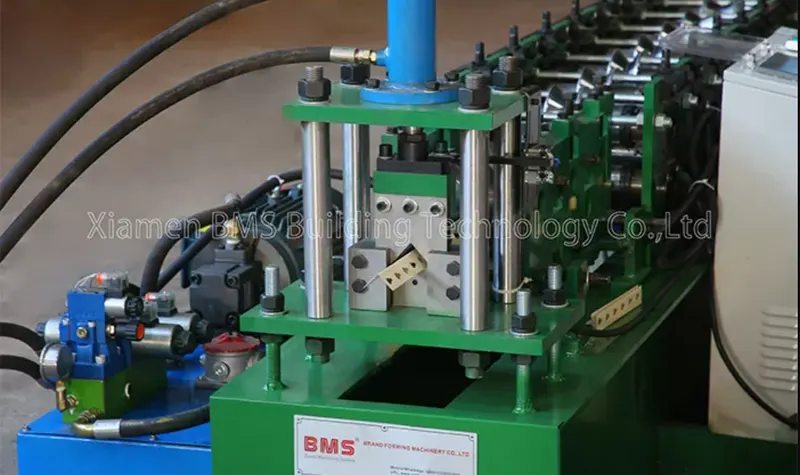
FIG :- TRIMMING AND PUNCHING
STEP 4 : DEBURRING
Deburring is a secondary operation of a maching process that enhances the final quality of the product by removing raised edges and unwanted piecee of material known as burs, left by the initial machining process. Burrs are creayed from shearinh , bending, cutting, piercing, and compressing materials. These are mostly seen on soft and ductile materils. Deburring machines are used to remove burrs by mechanical , electrochemical and therml methods.
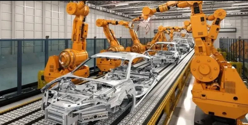
FIG:- DEBURRING
STEP 5 : WELDING
Welding is an integral part of manufacturing , especially in the autombile industry. The components of a vehicle need to withstand a significant amount of wear and tear over the course of vehciles life time. The process utilizes heat and pressure to provide a consistent, durable component.
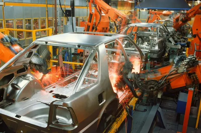
FIG :- WELDING
STEP 6 : GRINDING
Grinding is a processing method that uses abrasives to remove material. The process of removing material with abrasives is one of the earliest production techniques used by humans.
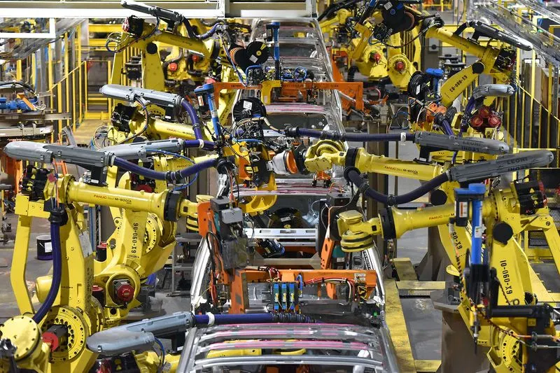
FIG :- GRINDING
STEP 7 : PAINTING
The automative paint adds " bling" to the car and makes it a shiny-new looking car. It increases the oomph of a standard product, making it highly valuable in terms of production value and presentation. The very important , automotive paint is different from any other generic paint It is made to last entire life of the car.
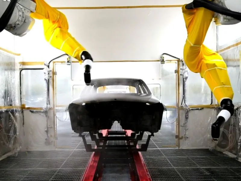
FIG :- PAINTING
STEP 8 : POLISHING
The polishing is process used in various components such as aerospace ,automotive, mechanical seals, fluid handling and many other precision engineering industries . Its is a final surface charactersistics of size, surface roughness. Its is used in many materials from steel to composite ceramics.
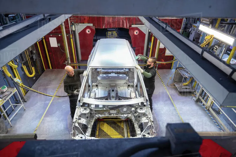
FIG : POLISHING
STEP 9 :- WAXING
Automotive or car wax is combined blend of carnauba wax mixed with natural oils , beeswax, and other petroleum distillates. These ingredients provude a thin layer of protection to the clear coat of paint on the top of the car body.
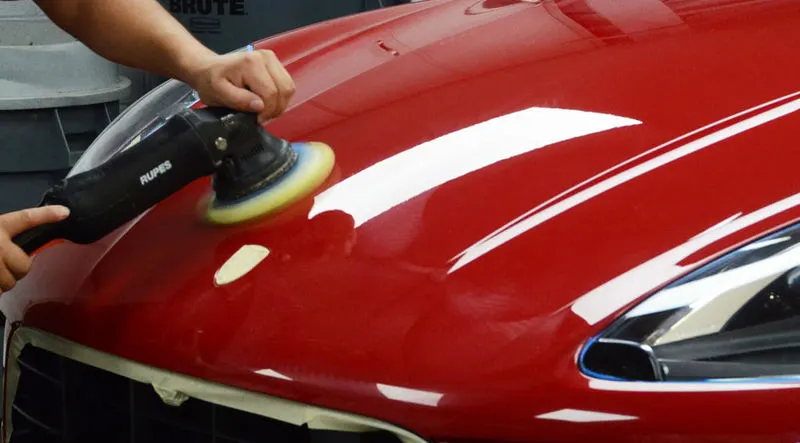
FIG :- WAXING
STEP 10 : COATING
Coating , in the context of corrosion , is the thin layers of cocering substance , deposited or applied on a surface of any object, mainly to improve its critical properties and to create a protective barried against deterioration of the surface due to its reaction with its environment.
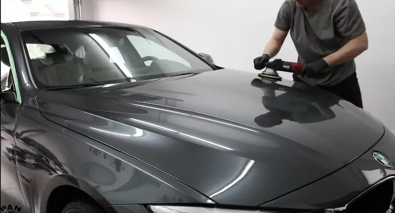
FIG : COATING
CONCLUSION
As per the master section the roof assembly and the essential flanges and reinforcements are created . The assembly position of the roof is checked for the given condition.