Roof Design
Challenge: Create an assembly by developing the essential flanges for the outer roof and creating the reinforcements.
Roof:-
An automobile roof or car top is the portion of an automobile that sits above the passenger compartment, protecting the vehicle occupants from sun, wind, rain, and other external elements. Because the earliest automobiles were designed in an era of horse-drawn carriages, early automobile roofs used similar materials and designs.
Fig 1: Roof
In later years, many variations on the automobile roof developed. These include:
Convertible:-
A convertible or cabriolet is a passenger car that can be driven with or without a roof in place. The methods of retracting and storing the roof vary among eras and manufacturers.
Fig 2: Convertible Roof
A convertible car's design allows an open-air driving experience, with the ability to provide a roof when required. A potential drawback of convertibles is their reduced structural rigidity. The majority of convertible roofs are of a folding construction framework with the actual top made from cloth or other fabric. Other types of convertible roofs include retractable hardtops (often constructed from metal or plastic) and detachable hardtops (where a metal or plastic roof is manually removed and often stored in the trunk).
Hardtop:-
A hardtop is a rigid form of automobile roof, typically metal, and integral to the vehicle’s design, strength, and style.
In limited cases, a hardtop roof can be detachable (often designed to store in the trunk), or retractable within the vehicle itself.
The pillarless hardtop (often referred to as simply "hardtop") is a body style of cars without a B-pillar.
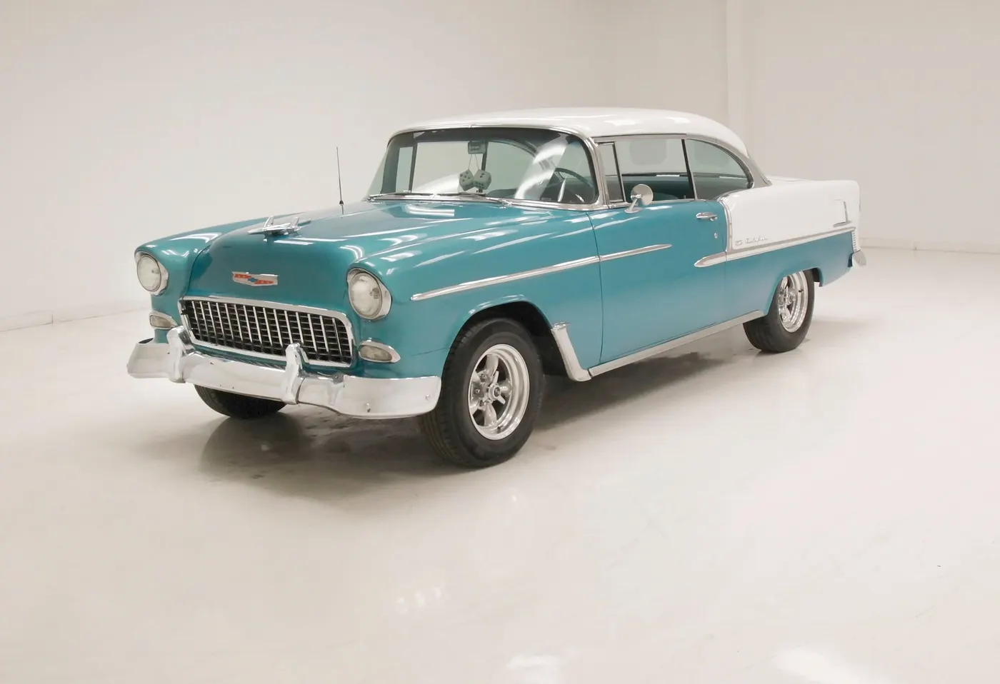
Fig 3: Hardtop Roof
Sunroof:-
A sunroof is a movable panel that opens to uncover a window in an automobile roof, allowing light and fresh air to enter the passenger compartment. Sunroofs can be manually operated or motor driven, and are available in many shapes, sizes, and styles. While the term "sunroof" is now used generically to describe any glass panel in the roof, the term "moon roof" was historically used to describe stationary glass panes rigidly mounted in the roof panel over the passenger compartment. A moon roof has a glass panel that is transparent and usually tinted. Previous terms include Sunshine Roof, Sliding Head, and Sliding Roof.
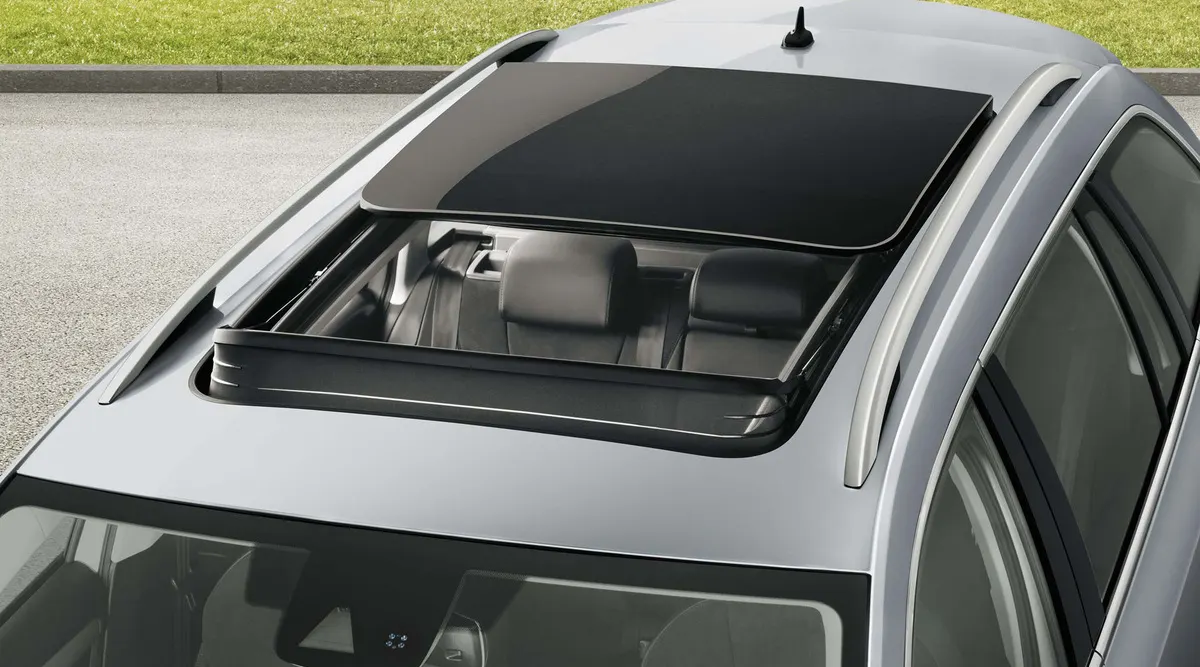
Fig 4: Sun Roof
T-top:-
A T-top is an automobile roof with a removable panel on each side of a rigid bar running from the center of one structural bar between pillars to the center of the next structural bar. The panels of a traditional T-top are usually made of auto-grade safety glass.
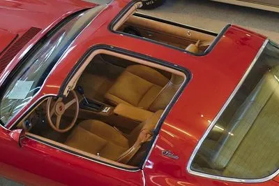
Fig 5: T-Top
Targa top:-
Targa top, or Targa for short, is a semi-convertible car body style with a removable roof section and a full-width roll bar behind the seats.
The rear window is normally fixed, but on some Targa models, it is a removable plastic foldable window, making it a convertible-type vehicle. Any normally fixed metal or trim that rises up from one side, over the roof, and down the other side is sometimes called a Targa band, Targa bar, or a wrap over the band.
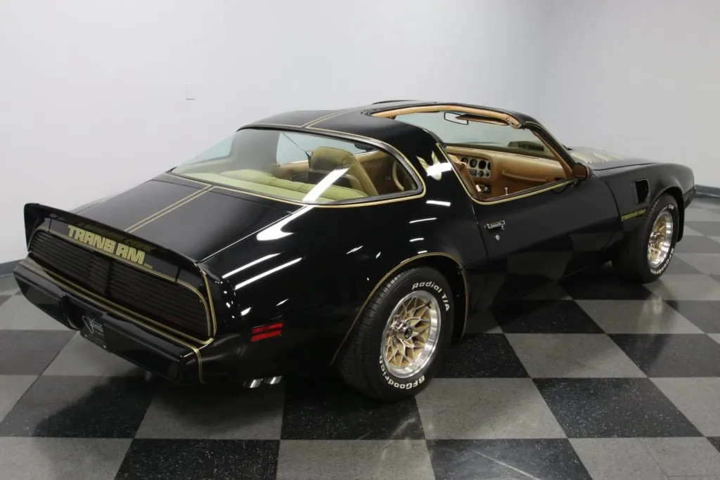
Fig 6: Targa top
Vinyl roof:-
A vinyl roof refers to a vinyl covering for an automobile's top
This covering was originally designed to give the appearance of a convertible to models with a fixed roof and eventually evolved into a styling statement in its own right. Vinyl roofs were most popular in the American market, and they are considered one of the period hallmarks of the 1970s domestic cars. Vinyl roofs were also popular on European- (especially UK-) and Japanese-built cars during the 1970s and tended to be applied to sporting or luxury trim versions of standard saloon (sedan) models.
Fig 7: Vinyl roof
Inputs for this Challenge:-
Class-A Surface
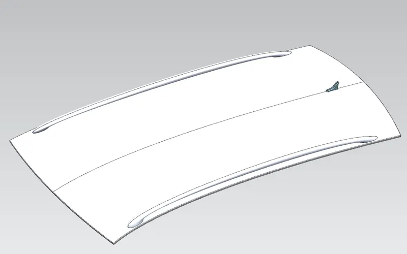
Fig 8: Given Class-A surface
Thickness
Roof Panel = 0.75mm
Front Roof Rail = 0.75mm
Bow Roof Rail -1&2 = 0.75mm
Center Roof Rail = 0.75mm
Rear Roof Rail = 0.75mm
Visibility Criteria:-
The visibility criteria of a driver are one of the most important factors when designing the roof. The roof should be designed such that it does not hinder the visibility range of the driver. The ditch area of the roof is designed keeping this criterion in mind.
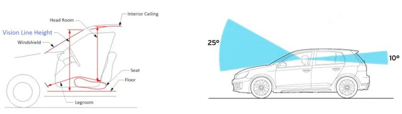
Fig 9: Visibility Criteria
Head Clearance:-
This factor is considered when designing the reinforcements of the roof. The reinforcements should be designed in a way that provides ample headroom clearance for the occupants in the car and does not collide with the head in case the car moves over a bump It should not act as a hindrance to the driver’s rear visibility.
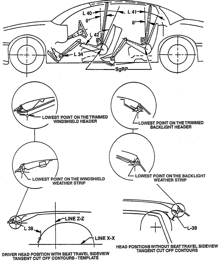
Fig 10: Head Clearance
Crush Test for Roof:-
Security point of view vehicle roof expect an incredibly indispensable part, especially in rollovers kind of accidents, in which the vehicle tips over onto its side of the roof. Likewise, vehicle rollover crashes are just a few fatalities and a couple of head, neck, and spine trauma all through the planet. Hence, voyager prosperity is also a crucial limit in front of OEMs. It isn't only an exhibiting system but also a responsibility determined by overall standards that are currently situated in a couple of countries and a regulatory need. Along these lines, strength is imperative for designing a vehicle roof. The strength of the roof design to inhabitant protection in certifiable rollover crashes requires the maximum moving distance of the roof development should be under 127 mm (5 in.) when the started load is 1.5 events the vehicle weight.
The voyager vehicle will be firmly situated or arranged on an even surface with the doorways secured and the window for the test. Additionally, a level, unyielding square with a lower surface a square shape assessing 30 inches wide by 72 crawls long (762mm X 1829mm) won't move more than 5 inches(127mm), assessed as the distance between the primary space of the lower surface of the test device and its territory as the predefined power level is reached, when it is used to apply the force of 1.5 events the unloaded vehicle weight (UVW) or 5000 lbs(22224N), whichever is less, to either side or forward edge of the vehicle. This test can be driven on either side of the roof structure, the front left or the front right side anyway not on the different sides in a solitary test, and still meets the necessities of the test. The unyielding plate won't move speedier than 0.5 inches/second and the force applied on the plate won't outperform the lesser of 1.5 events the unloaded vehicle weight (UVW) imparted in kilograms expanded by 9.8 or 5000lbs (22240N). Also, the orientation of the force will be sliding and perpendicular to the lower surface of the unbendable plate so much that it moves in a precise design without turning. The length of the test won't outperform 120 seconds. The longitudinal rotation of the plate is pitched forward at a 5 º point as seen from the side of the explorer vehicle.
The lateral axis or the move of the plate is so much that it shapes a 25 º separable point with a level surface as seen from the front of the voyager vehicle. The lower surface of the plate will reliably stay in contact with the outside of the roof. The fundamental point contact is 10 inches (254 mm) from the principle edge of the plate and as per the longitudinal axis on the lower side of the plate. Designed Roof. Following these design considerations and consequently creating the parts helps the vehicle with performing better, in reality, condition adhering to the testing limit which assurances to avoid or minimize the earnestness of injury during the episodes of the vehicle during lethal accidents
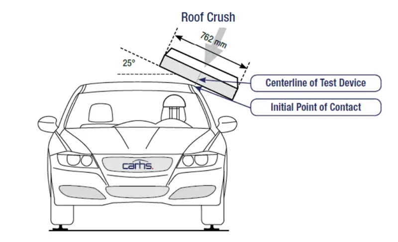
Fig 11: Crush Test for Roof Illustration
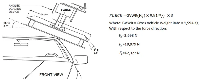
Fig 12: Crush Test parameters
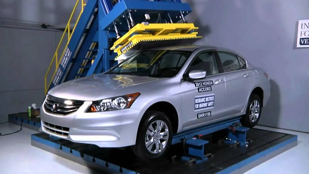
Fig 13: Crush Test on Car
Components Design
Roof:-
The roof is designed as per the master sections given by using the given Class-A surface. The roof surface is created then thickness is applied by 0.75mm
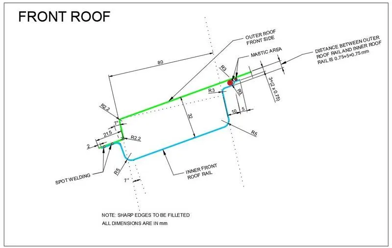
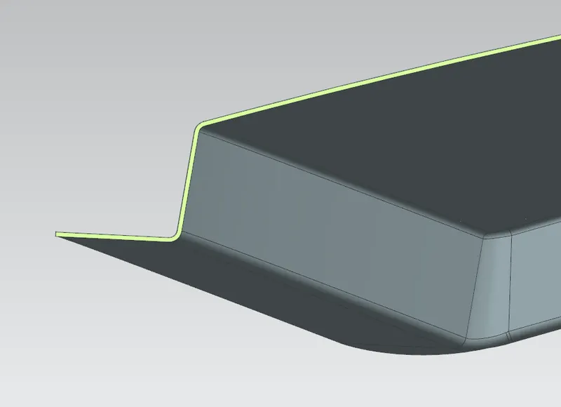
Fig 14: Front ditch of roof panel
The front portion of the Roof panel was created.
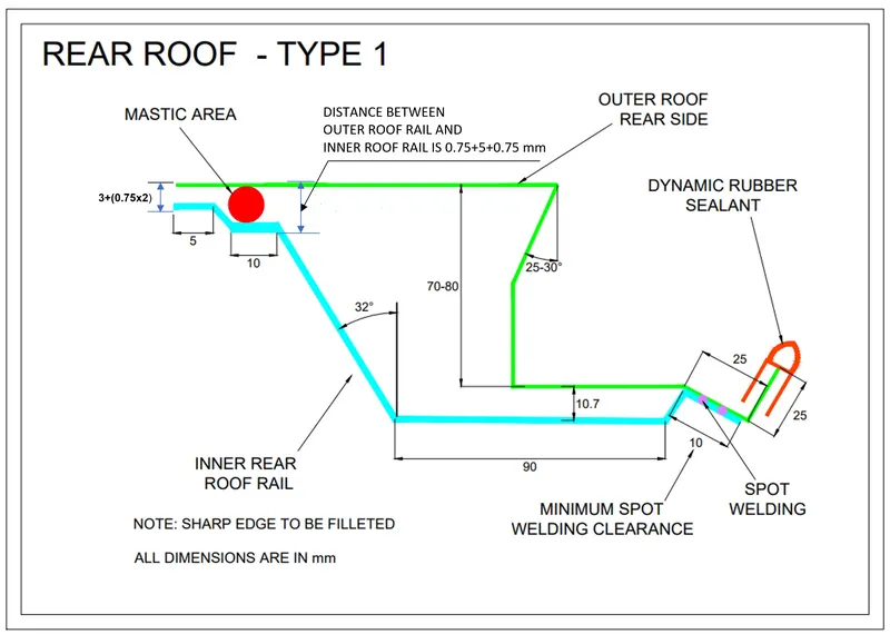
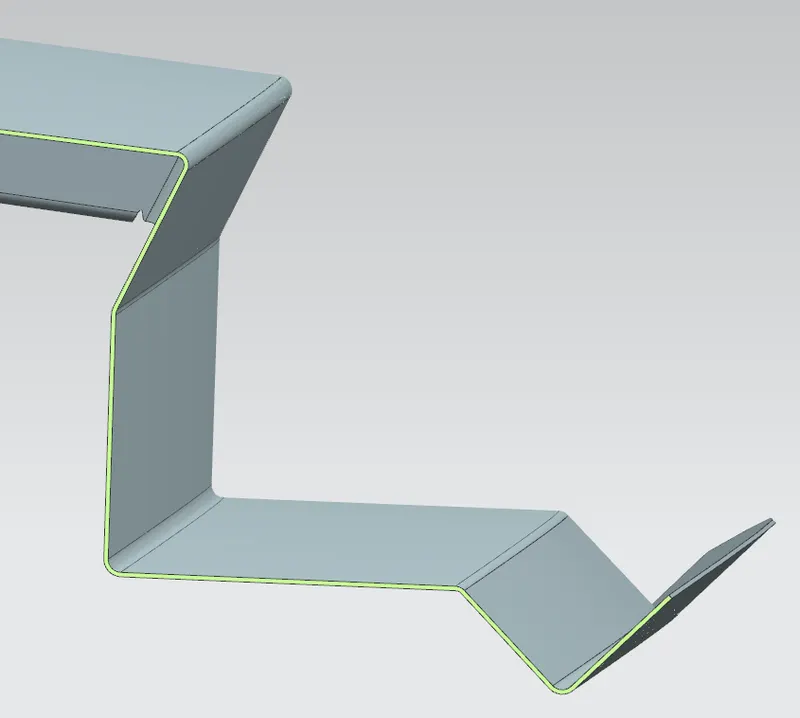
Fig 15: Rear ditch of roof panel
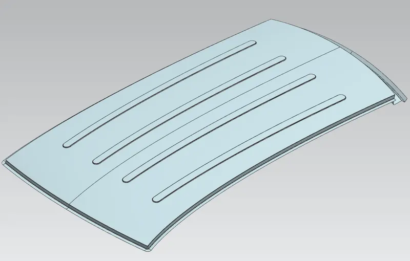
Fig 16: Roof panel
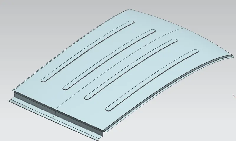
Fig 17: Roof panel
Front Roof Rail:-
This is the part that connects the roof ditch panel to the A-pillar of the car. Except for the roof panel all other parts provide strengthening aids to the roof panel. The Front rail is welded to the A-pillar and the roof panel. The front rail comes in the front part of the vehicle. The front rail upholds the rooftop outside shell at the front end. It is mounted with the assistance rooftop rail fortress on the two terminations. The rails are equipped with embosses to improve the strength over the length and the rail is connected with the external board utilizing mastic sealants on one side and the other joinery is spot welded.
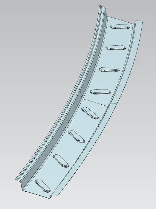
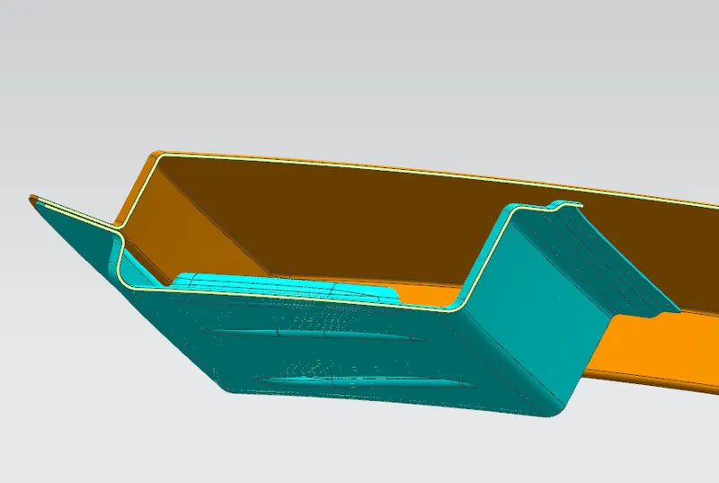
Fig 18: Front Roof Rail
Rear Roof Rail:-
The assistance is joined to the Back Door and the Body Side Outer and inner panels. Moreover, it is regularly created by utilizing the Body
Side Outer piece and thus the thickness of the rail is 0.65 mm. Like the Front Roof Rail design, we need to examine the rear Headroom
Clearance and the rear visibility principles while designing the Rear Roof Rail. Wellsprings of data are taken from the rear master section.
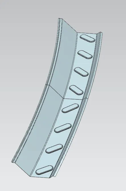
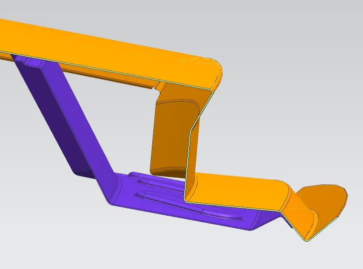
Fig 19: Rear Roof Rail
Bow Roofs:-
The Bow roofs are given to improve the torsional stiffness and load-bearing capacity of the roof structure. The number of bow roofs given will depend on the overall segments of the roof. The more expanded the roof more the bow roofs are fused into the BIW layout. They are associated with the outer board using mastic sealants. Each mastic point will have up to 80 mm indirect powerful area. The arranging of bow roofs is done ward on curve assessment. The heat distortion criteria and snow load criteria are checked to examine the circumstance of the bows in various conditions. These parts are added to increase the load-carrying capacity of the roof of the car.
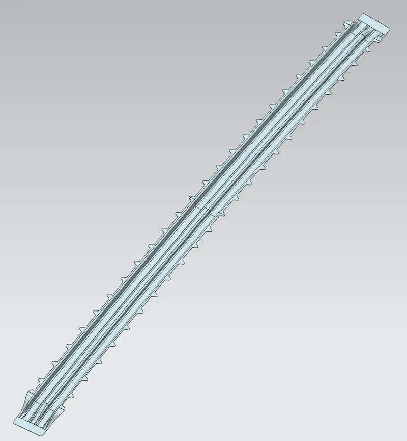
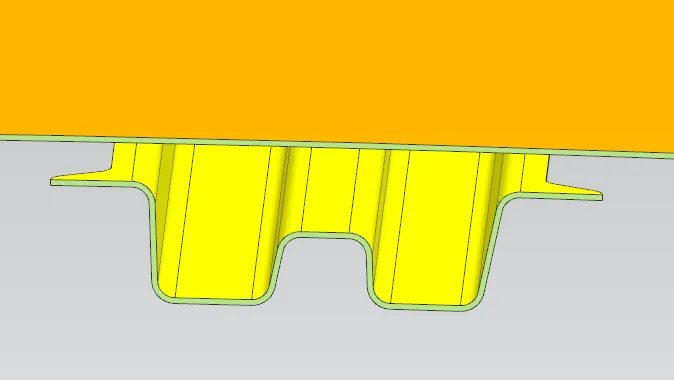
Fig 20: Bow Roof Rail-1
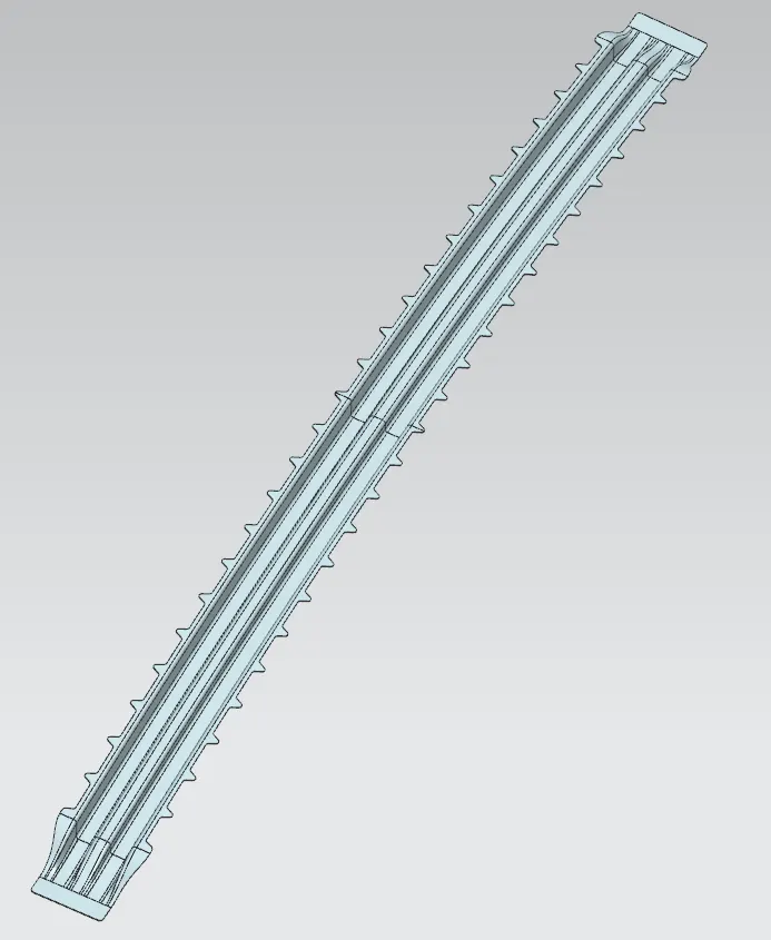
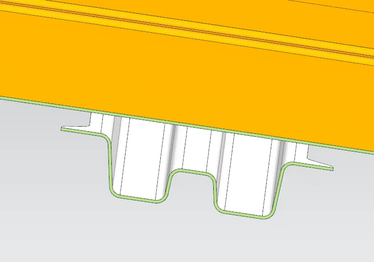
Fig 21: Bow Roof Rail-2
Center reinforcement:-
The center reinforcement is given to add more stiffness to the roof. It helps in increasing the load-carrying capacity of the roof and resists deformation caused due to any snow settling over the roof.
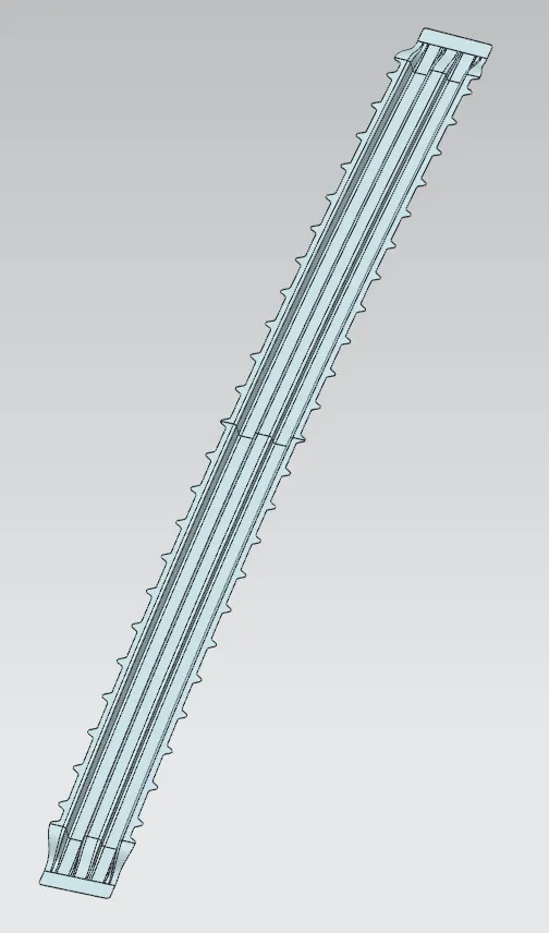
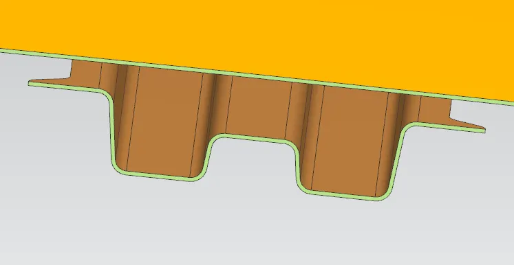
Fig 22: Center Roof Rail
Assembly:-
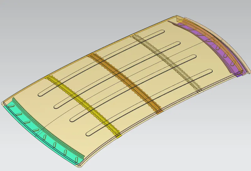
Fig 23: Roof Panel Assembly
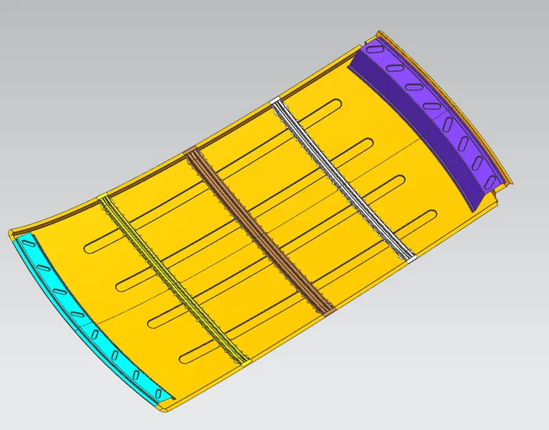
Fig 24: Bottom View of the Roof panel assembly
Heat Distortion calculations
W = [1.73 x 10^(-3) x L] + [1.85 x 10^(-8) x (R^2)/t] + [ 1.10x10^(-3) x l] - 2.68
Judgment Condition: OK< 2.7> 3.1
Where
L = Roof Length in X-Direction[mm](Roof dimension in 0-Y)
R = Roof curvature
R = 2(Rx*Ry)/(Rx+Ry)
Rx = X curvature
Ry = Y curvature
t = Roof plate thickness [mm]
l = Bow Roof Span [mm]
Procedure to measure the parameters.
On a plane parallel to the top plane draw a sketch in which the 0Y line is offset by 300 mm (3Y) on both sides of the 0Y line.
Draw lines perpendicular to the 0Y line passing through point exact midpoint of the two adjacent parts (e.g. midpoint between front rail and bow roof 1)
Offset these reference lines on both sides by 100 mm
Mark intersection points (red points) of the reference line (Yellow lines) and 100 mm offset lines.
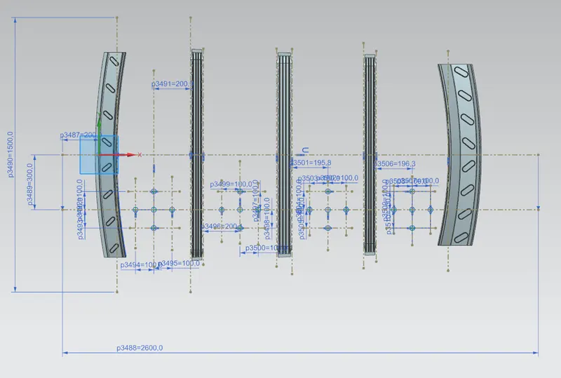
Fig 25: Heat Distortion calculations
These reference points are then projected on to roof's outer panel surface to create curves as shown.
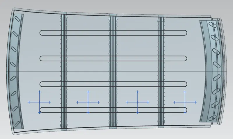
Fig 26: Heat Distortion calculations
Take all necessary measurements required to calculate the W value as per mentioned formula

Table 1: Heat Distortion calculations results
Snow load criteria calculations:-
Snow load criteria are useful to justify the bow roof rail position in snowfall regions. Due to snowfall, snow will get collected on the top roof which will tend to bend the roof. The bow roof will be in such a position that will provide more strength to the roof against bending.
Qr = [Iy x t2] / [α x s x [(Rx + Ry)/2]2 x 10-8]
Where
α = My x Lx2 x 10-12 , My = Y(Ly-Y)
Judgement condition = Qr ≥ 3.1
250 ≤ s ≤ 380
t = Roof plate thickness [mm]
Ly = Distance between the front and rear roof Rails on the Vehicle along with 0Y [mm]
Length of Roof panel with the center point between Roof rail Front /Rear as the reference point of the front and the rear.
Lx = Distance between the Left and Right end of the roof on the Roof BOW [mm]
The width of the roof panel is exposed on the surface.
Y = Distance front Front Roof Rail to Roof BOW [mm]
s = Distance for which Roof BOW bears divided load [mm]
s = L1/2 + L2/2
Iy = Geometrical moment of inertia of Roof BOW (Y cross-section) [mm4]
Rx = Lateral direction curvature radius of roof panel Y cross-section on Roof BOW [mm]
Roof panel curvature Radius of the Length Lx in Front view
Ry = Longitudinal Direction curvature radius of the Roof panel X cross-section on Roof BOW [mm]
Roof panel X curvature radius of length s in Side view
Procedure to calculate necessary parameters
On the plane parallel to the top plane draw a sketch in which 0Y is projected along the direction perpendicular to the top plane
Draw lines perpendicular to the 0Y line passing through point exact midpoint of the two adjacent parts (e.g., the midpoint between the front rail and bow roof 1)
Offset these reference lines on both sides by 100 mm
Mark intersection points (red points) of the reference line (Blue lines) and 100 mm offset lines (Yellow lines)
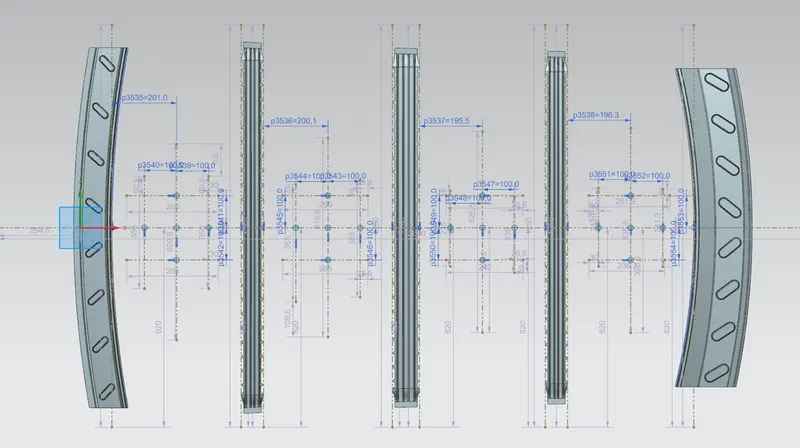
Fig 27: Snow load criteria calculations
These reference points are then projected on to roof’s outer panel surface to create curves as shown
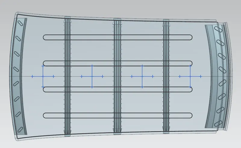
Fig 28: Snow load criteria calculations
Take all necessary measurements required to calculate Qr value as per mentioned formula
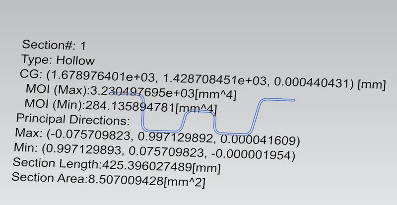
Fig 29: Bow Roof-1 section
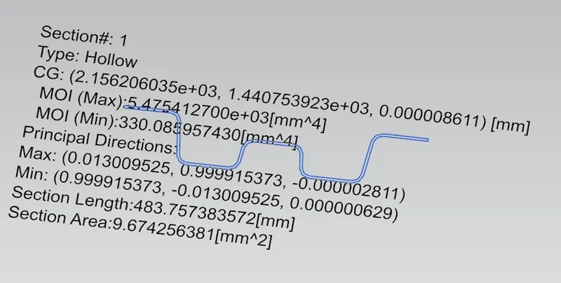
Fig 30: Bow Roof-2 section
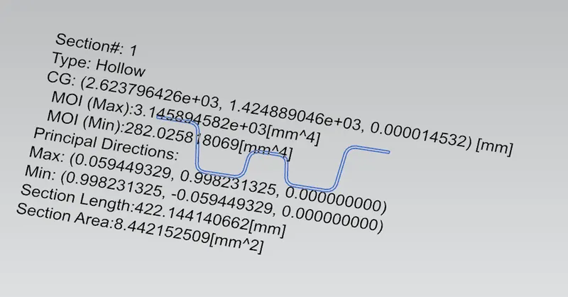
Fig 31: Center Roof rail section

Table 2: Snow load criteria calculations results
Draft Analysis:-
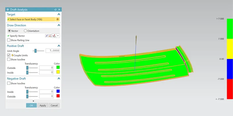
Fig 32: Draft Analysis on Roof Panel
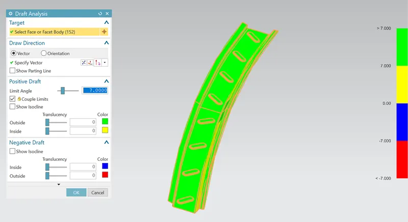
Fig 33: Draft Analysis on Front Roof Rail
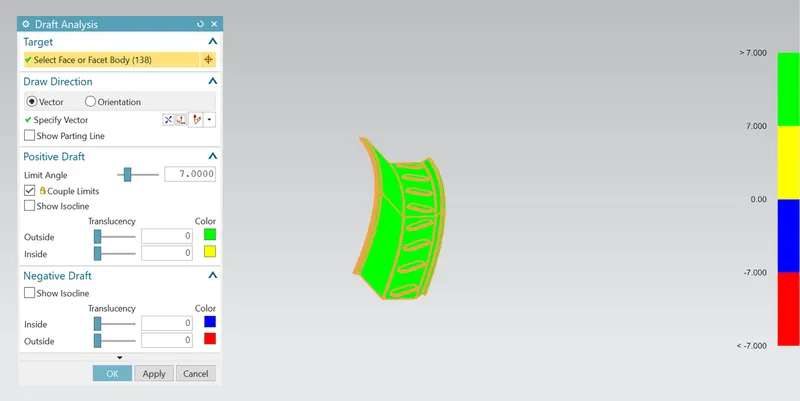
Fig 34: Draft Analysis on Rear Roof Rail
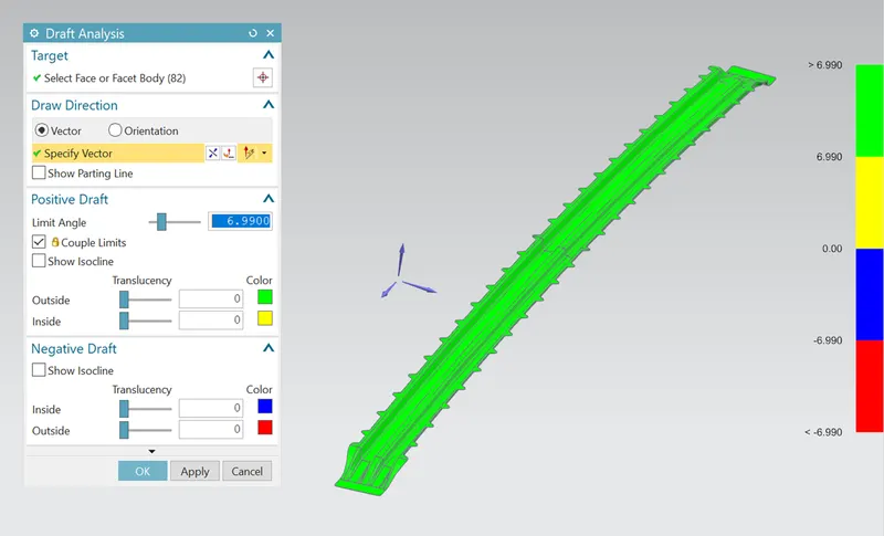
Fig 35: Draft Analysis on Bow Roof Rail-1
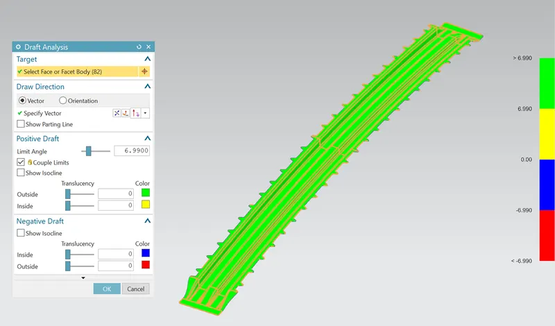
Fig 36: Draft Analysis on Bow Roof Rail-2
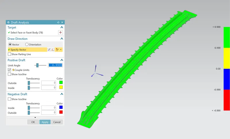
Fig 37: Draft Analysis on Center Roof Rail
Conclusion
- Ditch area flanges, Front roof rail, Bow roof rail 1&2, and Rear roof rail created as per input data.
- Heat distortion, Snow load was calculated & found that bow roof positions are OK
- Draft analysis results were good for all parts.