Roof Design
INTRODUCTION:-
The area of an automobile that is located above the passenger compartment and shields the passengers from the sun, wind, rain, and other environmental factors is known as the roof or car top.It is only closing the top portion when viewed from the exterior of the car. Yet, from a design standpoint, it is challenging to create the design. because there is no need to build support rails as the load can be supported without them.
Bow roofing are typically installed in flat areas to increase strength.Spot welding is used to secure the front and back roof rails to the ditch The mastic sealants are used to attach the front and back bow roofs, as well as the centre roof rails, to the roof.
OBJECTIVE:-
- The project's primary goal is to design the roof through sheet metal design in NX Cad 12. Other goals include designing the front roof rail, rear roof rail, bow roof front, bow roof rear, centre roof rail, and reinforcement to form a strengthen roof.
- To identify where the bow roofs should be located, undertake a curvature study on the roof and performance calculations for the heat distortion and snow load criteria.
- calculating the section modulus and moment of inertia for Bow roofs with a central roof rail. both the front and rear roof rails.
- Performing the draft analysis for front roof rail, rear roof rail, bow roof rail, centre roof rail and roof outer .
DESIGN CONSIDERATION:- The following are the design consideration that are used while designing the roof.
- Visibility criteria
- Head clearance
- Curvature study
- Hear distortion and snow load criteria
- Draft analysis.
COMPONENTS OF ROOF:- The components of the roof are as follows.
1. Front Roof Rail:- The front roof rail is situated where the wind shield connects to the roof at the front of the vehicle. For the bottom flange, the vision requirements and the passenger's headroom clearance are taken into account. For greater strength, the rail is bonded at one end using spot welding and at the other with the roof using mastic sealants.
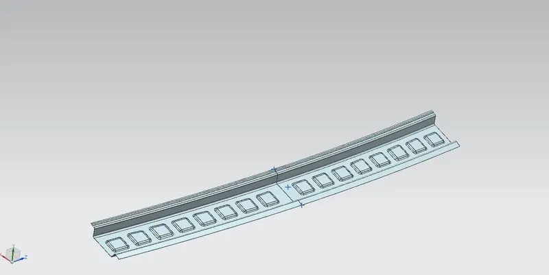
Fig 1: Front Roof Rail
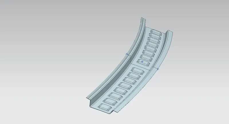
Fig 2 : Front Roof Rail
2. Bow Roof Rail Front:-A bow roof is an extra supporting element added to the roof to boost strength and ensure compliance with standards. Mastic sealants are used to join the two ends together to boost strength and preserve the roof's aesthetics.
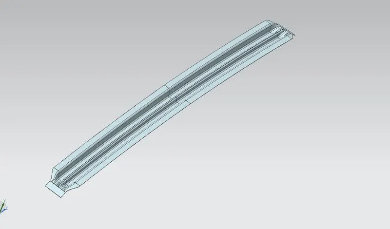
Fig 3: Front Bow Roof Rail
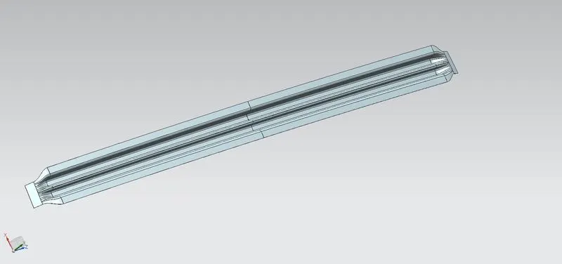
Fig 4: Front Bow Roof Rail
3. Rear Roof Rail:- The rear entrance and the roof outer are connected by this roof rail. This roof rail is developed by keeping in mind the design consideration of the the backdoor. Spot welding is used in this instance to join one end, while mastic sealants are used to join the other end.
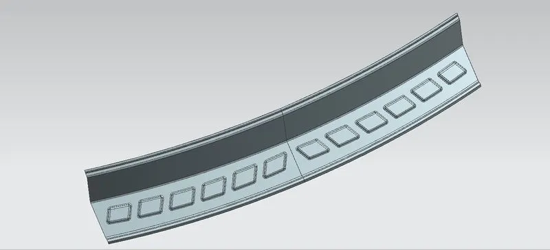
Fig:5 Rear Roof Rail
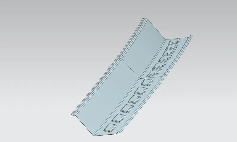
Fig 6: Rear Roof Rail
4. Bow Roof Rail Rear:- The purpose of this bow roof is the same as that of the bow roof rail front one. This one is situated at the back between the rear roof rail and the centre bow roof.
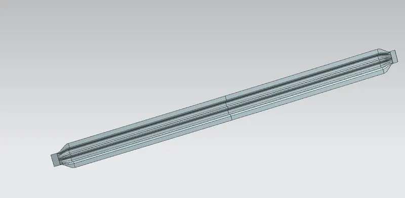
Fig 7: Rear Bow Roof Rail
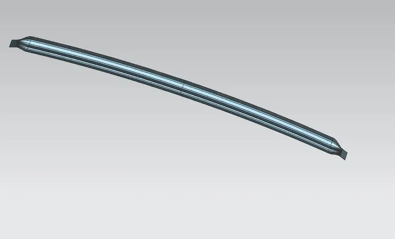
Fig 8: Rear Bow Roof Rail
5. Centre Bow Roof Rail:- The flat portion of the roof is more prone to failure due to the action of stress, hence a central roof rail aids in properly supporting it. The B-pillar support structure is connected to the central roof rail, which is typically located at the centre of the roof. During the roll-over test, this central roof rail contributes to the strength of the roof.
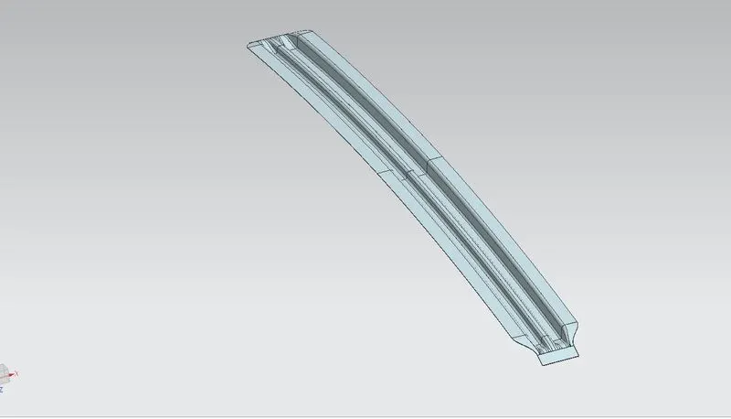
Fig 9: Centre Bow Roof Rail
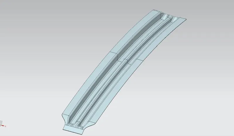
Fig 10: Centre Bow Roof Rail
6. Front Ditch Area:- When there is an accident, the front roof rail is utilised to support the roof from external pressures. Although strengthening the front roof rail is a beneficial thing, drivers do not like it since it hide their view of the road.
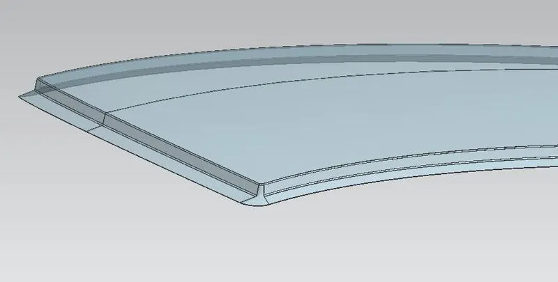
Fig 11: Front Ditch Area
7. Rear Ditch Area:- The back door must be fixed in this region while designing the rear roof ditch area, just as it is with the front roof ditch area.
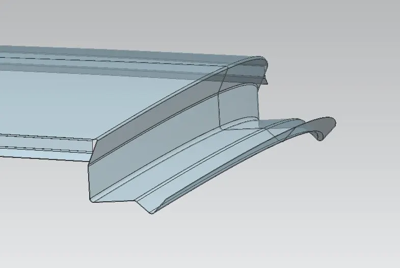
Fig 12: Front Ditch Area
CURVATURE STUDY ON THE ROOF:-
- Heat Distortion
- Snow Load
HEAT DISTORTION:- The use of sheet metal benefits greatly from the research of thermal distortion. The temperature at which a material cannot be utilised for structural purpose is known as the heat distortion limit. This study is helpful in determining the point at which a material begins to soften when subjected to a fixed load at a high temperature. Based on the heat distortion temperature, damage to the roof should be avoided. This study will show in what bow roof position the roof is sufficiently strengthened.
Bow Roof Prediction Formula:-
HEAT DISTORTION CRITERIA:-
W = [1.73 x 10^(-3) x L] + [1.85 x 10^(-8) x (R^2)/2] + [1.10 x 10^(-3) x I]-2.68
Judgement Condition: OK<2.7>3.1
Where,
L= Roof Length in X- direction [mm](Roof Dimension in 0-Y)
R = Roof curvature
R = 2(RX*RY)/(RX+RY)
RX = X Curvature
RY = Y Curvature
t = Roof plate thickness [mm]
I = Bow roof span [mm]
Thickness for the Roof(t):
Roof Outer Panel, t= 0.75mm
Front Roof Rail, t = 0.75mm
Rear Roof Rail, t = 0.75mm
Bow Roof Rail Front, t = 0.75mm
Bow Roof Rail Rear, t = 0.75mm
Reinforcement roof rail, t = 0.75mm
Length of Roof (L):-
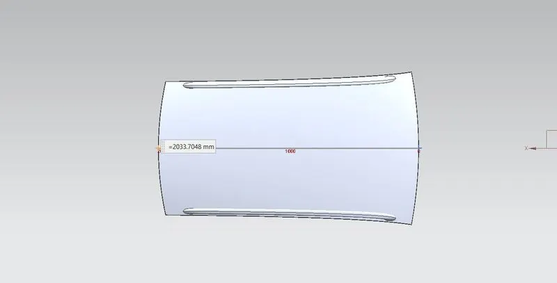
Fig 13:- Length of Roof
BOW ROOF SPAN (l):- For finding the bow roof span(l) we will take the distance from front roof rail to bow roof front for the 1st section and in the similar way we will measure the other 3 sections value
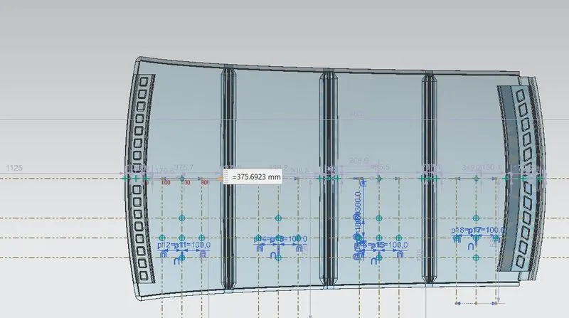
Fig 14:- Bow Roof Span(l)
RX & RY (X & Y Curvature):-
- In the perpendicular plane, at a distance of 300mm from the 0-Y axis, a parallel line is drawn. 100mm lines are then displaced on each side of the -3Y line after that. Center lines are now drawn in between each pair of neighbouring roof rail edges. On the sketch, intersection locations are shown or marked. All the geometric lines, except the points, make them construction lines.
- After that intersection points are projected on the roof surface.
- Join the the points with the 3-Point arc and take out the radius Rx and Ry for a particular section.
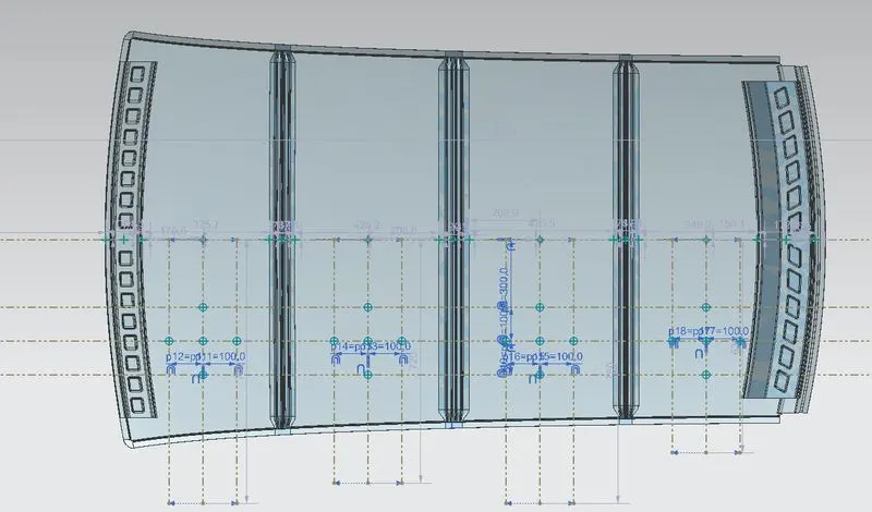
Fig 15:- Rx and Ry Curvature for Heat Distortion Criteria
Ry Value:-
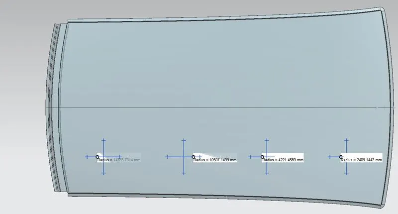
Fig 16:- Ry Radius Value
Rx value:-
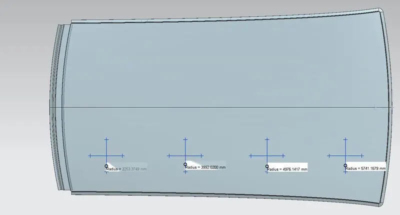
Fig 17:- Rx Radius Value
FINAL RESULTS OF HEAT DISTORTION:
We have the necessary values for finding the heat distortion value(W):
W = [1.73 x 10^(-3) x L] + [1.85 x 10^(-8) x (R^2)/t] + [1.10 x 10^(-3) x l]-2.68

Fig 18:- Heat Distortion Calculations
From the above table shown in the fig 18 we, conclude that all the values are of W< 2.7. So, that all bow roofs areas are placed at the right place.
SNOW LOAD:-The effectiveness of the roof's capacity to endure snowfall on the roof and recover its original shape once the weight has been removed is tested using a snow load criterion study.
Snow Load Prediction Formula
Qr = [Iy x t2] / [α x s x [(Rx + Ry)/2]2 x 10-8]
Note: The Qr value given over here is correct. There was a typo error in the formula given in the video.
Where,
α = My x Lx2 x 10-12 , My = Y(Ly-Y)
t = Roof plate thickness [mm]
Ly = Distance between the front and rear roof Rails on the Vehicle along with 0Y[mm]
Length of Roof panel with the center point between Roof rail Front /Rear as the front and rear reference point.
Lx = Distance between the Left and Right end of the roof on the Roof BOW [mm]
The width of the roof panel is exposed on the surface.
Y = Distance front Front Roof Rail to Roof BOW[mm]
s = Distance for which Roof BOW bears divided load [mm]
s = L1/2 + L2/2
Iy = Geometrical moment of inertia of Roof BOW (Y cross-section )[mm4]
Rx = Lateral direction curvature radius of roof panel Y cross-section on Roof BOW [mm]
Roof panel curvature Radius of the Length Lx in Front view
Ry = Longitudinal Direction curvature radius of the Roof panel X cross-section on Roof BOW [mm]
Roof panel X curvature radius of length s in Side view
Judgment condition
Qr ≥ 3.1
250 ≤ s ≤ 380
Rx & Ry (X and Y Curvature):-
- On a plane perpendicular to the roof, at Y=0. Draw two 100mm lines offset from the 0Y axis line. Center lines are now drawn between each subsequent roof rail. On the sketch, intersection locations are shown. Make all of the geometry, except points, in construction lines.
- After that intersection points are projected on the roof surface..
- Join the the points with the 3-Point arc and take out the radius Rx and Ry for a particular section.
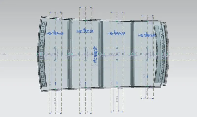
Fig 19:- Rx and Ry Curvature for Snow Load Criteria
Rx Value:-
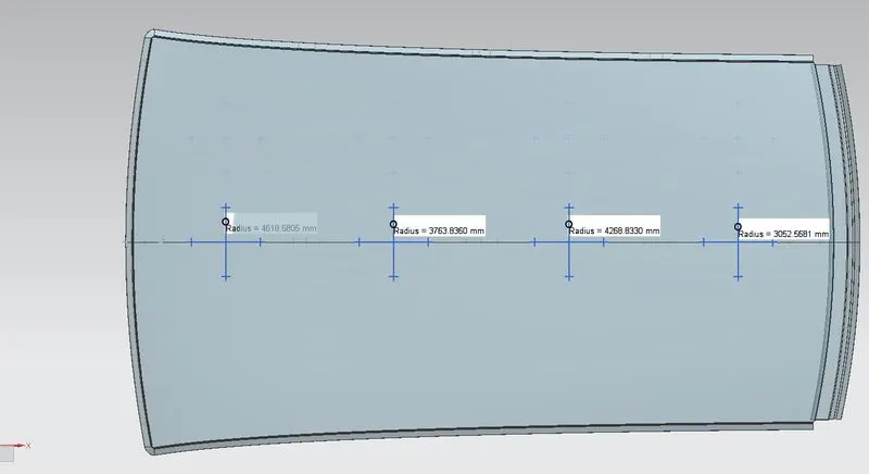
Fig 20:- Rx Rdaius Of Curvature Value
Ry Value:-
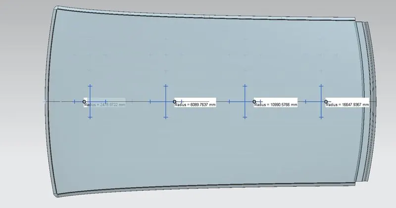
Fig 21:- Ry Radius of Curvature Value
Length of Roof (Ly):-
Fig 22:- Length of Roof
LX1Value:-
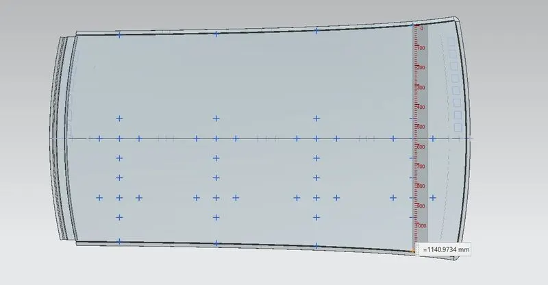
Fig 23:- Lx1 value
LX2Value:-
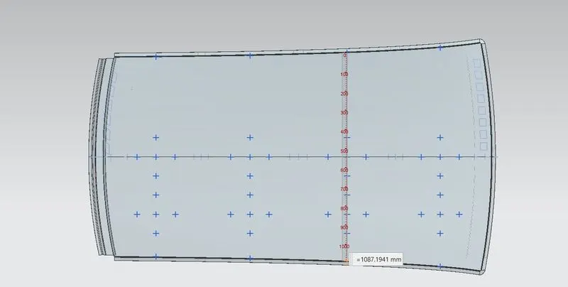
Fig 24:- Lx2 value
LX3Value:-
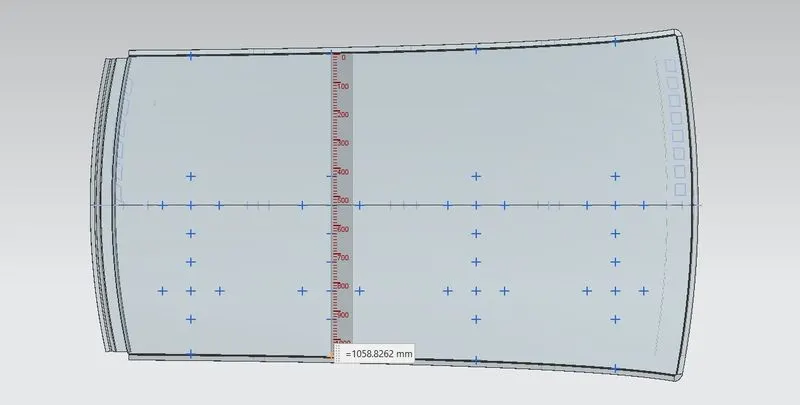
Fig 25:-LX3Value
MOMENT OF INERTIA:-
Front Bow Roof Rail:-
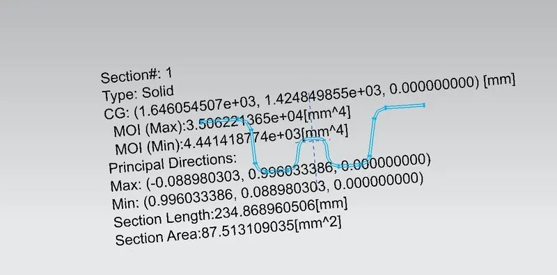
Fig 26:- Front Bow Roof Rail MOI
Here, we take the Minimum moment of inertia value is IY1 = 4441.4877mm4.
Centre Bow Roof Rail:-
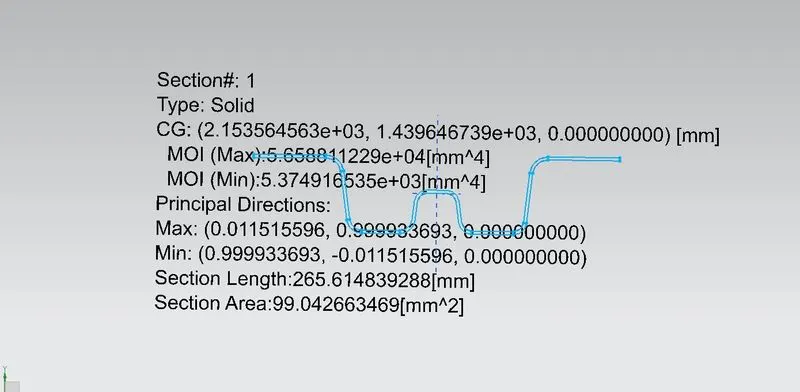
Fig 27:- Centre Roof Rail MOI
Here, we take the Minimum moment of inertia value is IY1 = 5374.9165mm4.
Rear Bow Roof Rail:-
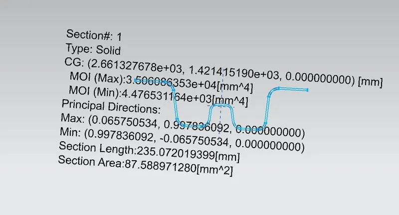
Fig 28:- Rear Bow Roof Rail MOI
Here, we take the Minimum moment of inertia value is IY1 = 4476.5311mm4.
Front Roof Rail:-
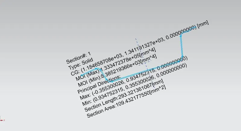
Fig 29:- Front Roof Rail MOI
Here, we take the Minimum moment of inertia value is IYmin = 8385.219mm4.
Here, we take the Maximum moment of inertia value is IYmax = 133342.723mm4.
Rear Roof Rail:-
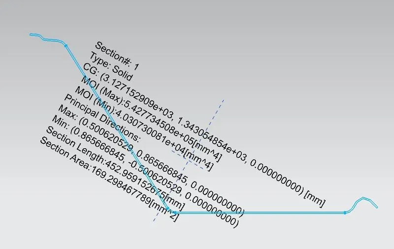
Fig 30:- Front Roof Rail MOI
Here, we take the Minimum moment of inertia value is IYmin = 40307.30mm4.
Here, we take the Maximum moment of inertia value is IYmax = 542773.4mm4.
Results For Snow Load Criteria:-

Fig 31:- Snow load Criteria Table
It is observed from the values that obtained values of QR > 3.1
Draft Analysis:-
You may determine if the portion you drafted will be simple to remove using the Draft Analysis tool. In this kind of analysis, zones on the investigated element are identified by colour ranges where the deviation from the draught direction at any given place corresponds to predetermined values.
For analysis, a minimum draught angle of 7° is taken into account. Green indicates that a part has positive draft angle greater than 7° and has passed analysis when all of the pieces are facing the tooling direction.
DRAFT ANALYSIS FOR FRONT ROOF RAIL :-
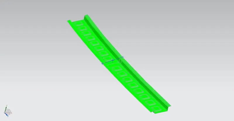
Fig 32:- Front Roof Rail Draft Analysis
DRAFT ANALYSIS FOR BOW ROOF RAIL - 1 or Front Bow Roof Rail
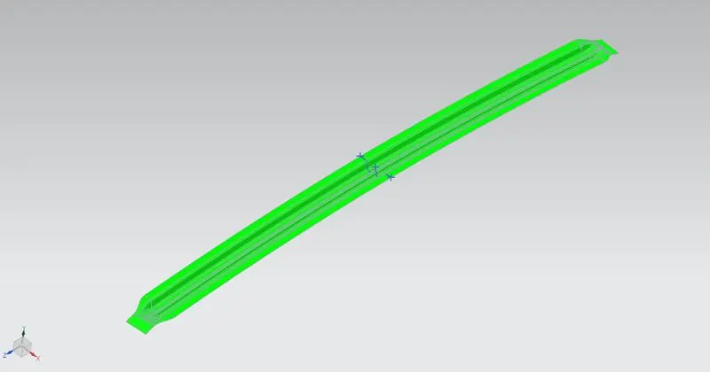
Fig 33:- Front Bow Roof Rail Draft Analysis
DRAFT ANALYSIS FOR BOW ROOF RAIL - 2 or Rear Bow Roof Rail
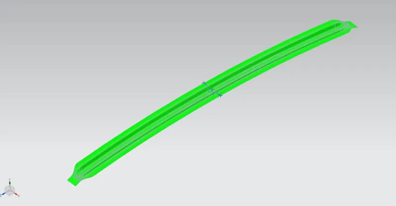
Fig 34:- Rear Bow Roof Rail Draft Analysis
DRAFT ANALYSIS FOR CENTRAL ROOF RAIL :
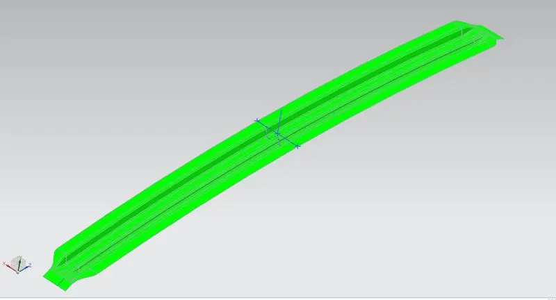
Fig 35:- Central Roof Rail Draft Analysis
DRAFT ANALYSIS FOR REAR ROOF RAIL :
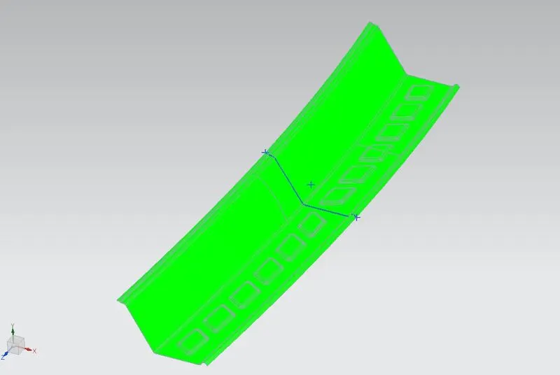
Fig 36: DRAFT ANALYSIS FOR REAR ROOF RAIL
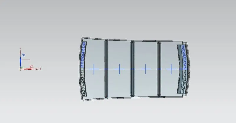
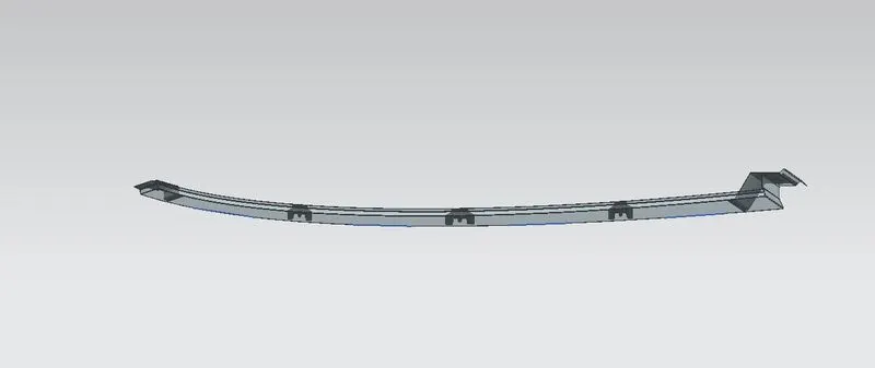
Different Views of Roofs:-
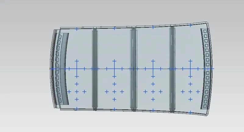
Fig:
Conclusions:-
Hence the roof , front roof rail, bow roof rails , central roof rail and the rear roof rail is designed by following the master sections and the moment of inertia and draft analysis are carried out to check feasibility manufacturing.