Roof Design
Roof Design
Aim/Objective -
1. To design a roof of a car by developing the essential flanges for the outer roof and creating the reinforcements like bow roofs, front roof rail, center roof rail and rear roof rail using the master sections provided.
2.To calculate the heat distortion and snow load criteria.
3.To do the draft analysis of all the parts.
Introduction:
The Roof of a car is the component that encloses the passenger compartment from the top. It protects the Passengers and the interior of the car from external environments thus providing a safe and isolated cabin. The roof plays an important role in safety, especially in the case of rollover accidents. To achieve better safety results the roof is designed with reinforcement structures such as rails.
Types of Roofs in Automobile industries -
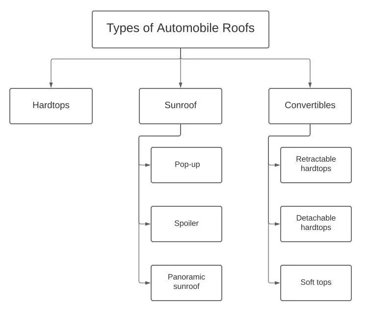
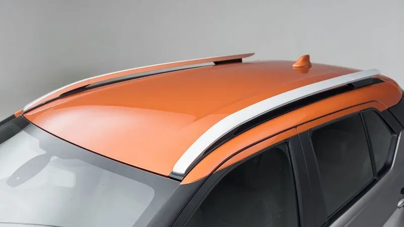
In this Project I am designing HARDTOP type of Roof -
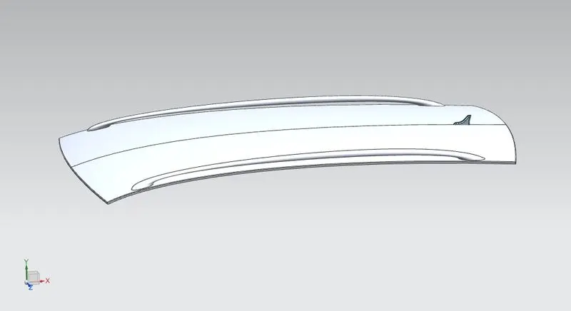
Given Roof Skin Data -
The rails and reinforcement are joined to the ditch area with a spot weld where it’s not the styling part.
The required tool opening angle is minimum 3 Degrees.
Factors which are considered before creating the Roof -
- Headroom Clearance
- Visibility Criteria
- Back door Assembly
- Wind shield Assembly
- Heat distortion and Snow load criteria
- Draft analysis
The Automobile Roof consists of the following major Componenets :
- The Roof outer panel
- Front roof Rail
- Rear Roof Rail
- Centre Roof Rail
- Bow Roofs
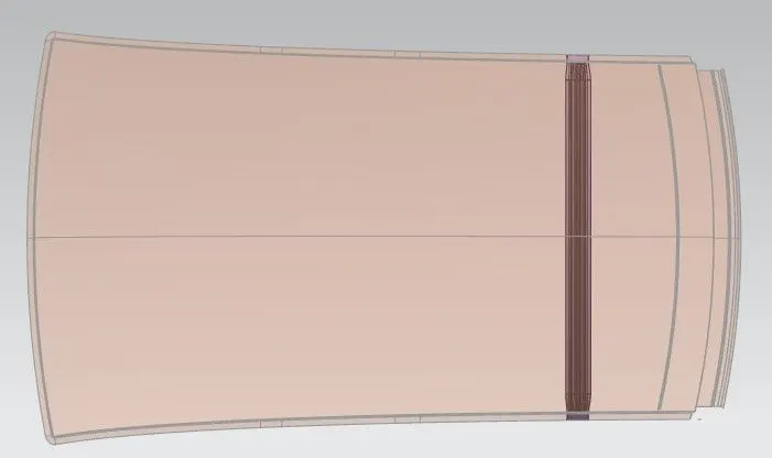
The Roof outer panel -
The roof is the aesthetic part to which all the reinforcement rails get joined by spot welds at the edges and matics at the center of the roof.
After Creating Ditch Areas -
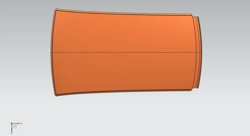
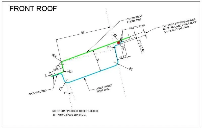
FRONT ROOF RAIL:
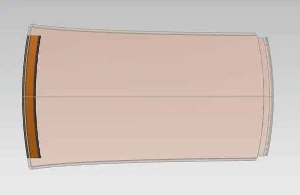
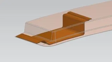
The front roof rail is created at the front side of the roof to provide strength to the roof while designing the Front Roof Rail headroom clearance and the driver visibility are the two important factors to be considered.The front roof rail is connected to the roof outer panel with the help of mastic sealants.
Master Section For Front Roof Rail-
Front Roof Created As Per Master Section-
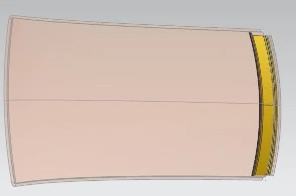
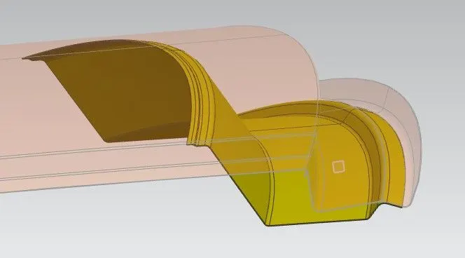
Rear Roof Rail
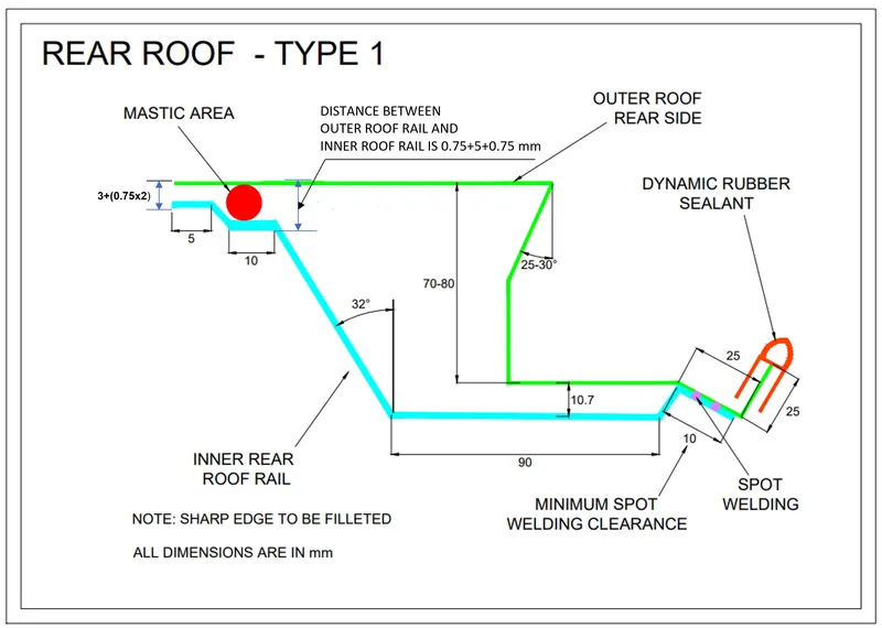
Rear roof rail is the one of the important components of roof assembly which is used for the back door mounting similar to front roof rail important design consideration include rear passenger head clearance rear visibility of the vehicle. It is also improving the strength of the roof.
Master Section For Rear Roof Rail-
Rear Roof Created As Per Master Section-
Center Roof Rail
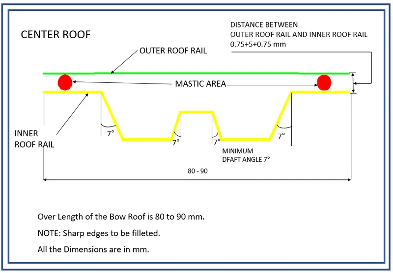
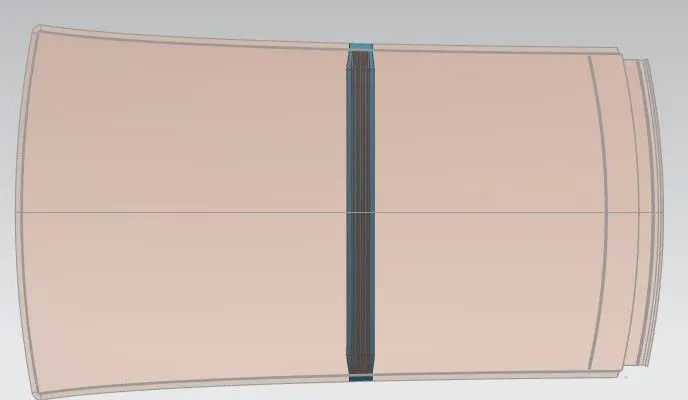
- Center roof rail helps in providing support to the flat area of the roof as it is more susceptible to failure under the action of load. Generally center roof rail is placed at the center of the roof which is connected to the B-pillar support structure.
- Mastic sealants are used for joining center roof rails to the roof.
- Embossing can be added to further increase the strength.
Master Section For Center Roof Rail-
Center Roof Created As Per Master Section-
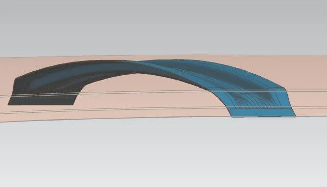
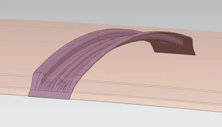
Bow Roofs
The bow roofs are used to improve the torsional stiffness and load bearing capacity of the roof structure. Bow roofs are placed on the flat regions of the roof which provides strength in bigger curvature region . The number of bow roofs present depends on the overall size of the roof.
Master Section For Bow Roof Rail-
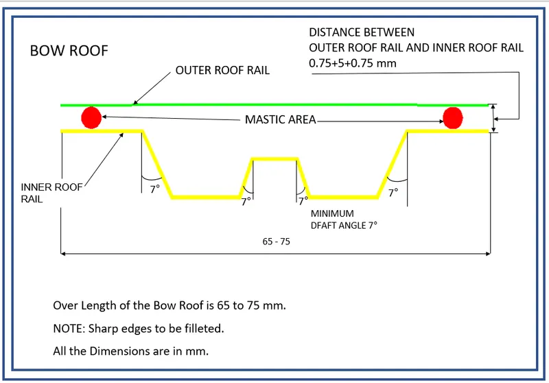
Bow Roof Created As Per Master Section-
Bow Roof 1
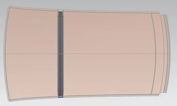
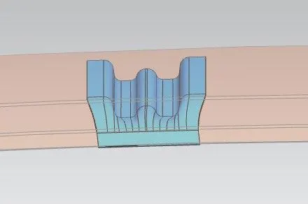
Bow Roof 2
CURVATURE STUDY ON THE ROOF:
- Heat Distortion
- Snow Load
HEAT DISTORTION:
The heat distortion study plays an important role in Sheet metal application. Heat distortion is a temperature limit above which material cannot be used for structural application. This study is useful to find where the material starts to soften when exposed to a fixed load at elevated temperatures. In order to avoid bending, damage to the roof is based on the heat distortion temperature. This study will provide which position of the bow roof gives enough strength to the roof.
Bow–Roof Prediction Formula -
W = [1.73 x 10^(-3) x L] + [1.85 x 10^(-8) x (R^2)/t] + [ 1.10x10^(-3) x l] - 2.68
Where,
L = Roof Length in X-Direction[mm](Roof dimension in 0-Y)
R = Roof curvature
R = 2(Rx*Ry)/(Rx+Ry)
Rx = X curvature
Ry = Y curvature
t = Roof plate thickness [mm]
l = Bow Roof Span [mm]
Judgment Condition
OK< 2.7
Here ,
The thickness of entire roof plate is ( t ) = 0.75
ROOF LENGTH (L):
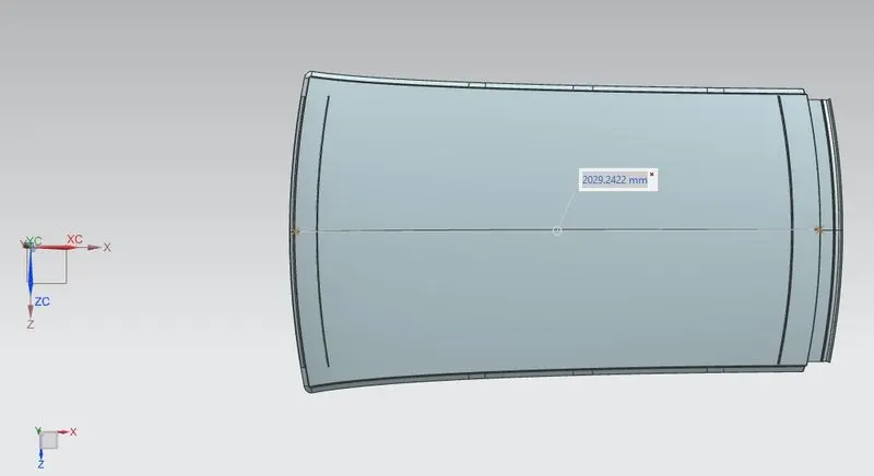
Roof Legth is =2029.2422
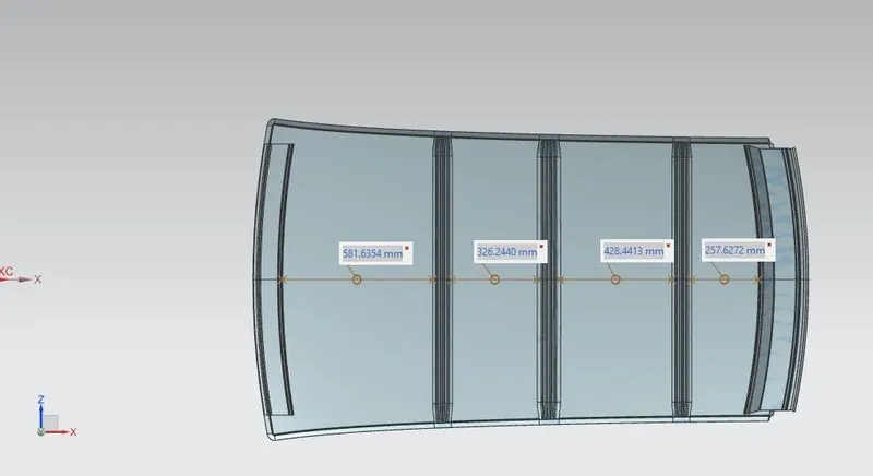
BOW ROOF SPAN (l):
Distance B/w one reinforcement to other -
RX & RY (X & Y Curvature):
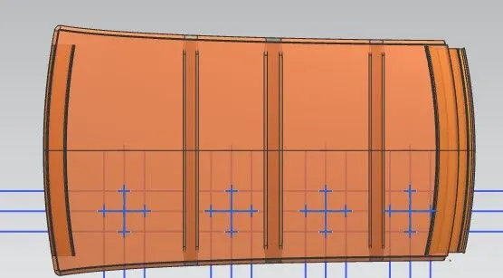
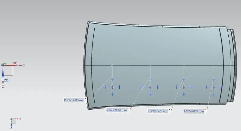
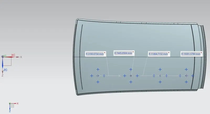
- From 0-Y axis, at -3Y about distance 300mm is drawn parallel on the perpendicular plane. After that 100mm lines are offset to either side of -3Y line. Now center lines are drawn between each adjacent roof rail edges respectively. Intersection points are marked on the sketch. Make all geometry lines are construction lines except points.
- Project the intersection points on sketch to the Roof surface.
- Join the intersection points in roof surface using the arc curve an measure the radius using the minimum radius comment.
RX Value:
RY Value:
FINAL RESULTS OF HEAT DISTORTION:
We have the necessary values for finding the heat distortion value(W):
W = [1.73 x 10^(-3) x L] + [1.85 x 10^(-8) x (R^2)/2] + [1.10 x 10^(-3) x I]-2.68
Apply the all the values,
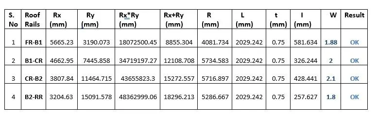
From the above table we, conclude that all the values are of W< 2.7 and also W> 3.1. So, that all bow roofs areas are placed at the right place.
SNOW LOAD CRITERIA :
This test is done to know how is the roof behaving when there is a snow over . normally due to the snow weight the dent will happen. But the roof should be designed in such a way that when the snow is removal the roof should go it its original position . This is the basic requirements for snow load criteria .
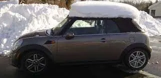
Snow Load Prediction Formula -
Qr = [Iy x t2] / [α x s x [(Rx + Ry)/2]2 x 10-8]
Note: The Qr value given over here is correct. There was a typo error in the formula given in the video.
Where,
α = My x Lx2 x 10-12 , My = Y(Ly-Y)
t = Roof plate thickness [mm]
Ly = Distance between the front and rear roof Rails on the Vehicle along with 0Y[mm]
Length of Roof panel with the center point between Roof rail Front /Rear as the front and rear reference point.
Lx = Distance between the Left and Right end of the roof on the Roof BOW [mm]
The width of the roof panel is exposed on the surface.
Y = Distance front Front Roof Rail to Roof BOW[mm]
s = Distance for which Roof BOW bears divided load [mm]
s = L1/2 + L2/2
Iy = Geometrical moment of inertia of Roof BOW (Y cross-section )[mm4]
Rx = Lateral direction curvature radius of roof panel Y cross-section on Roof BOW [mm]
Roof panel curvature Radius of the Length Lx in Front view
Ry = Longitudinal Direction curvature radius of the Roof panel X cross-section on Roof BOW [mm]
Roof panel X curvature radius of length s in Side view
Judgment condition
Qr ≥ 3.1
250 ≤ s ≤ 380
RX & RY (X & Y Curvature):
- At 0-Y axis on perpendicular plane to roof. Draw 100mm lines offset to either side of the of 0Y axis line. Now center lines are drawn between each adjacent roof rail respective. Intersection points are marked on the sketch. Make all the geometry in construction lines except points.
- Project the intersection points in the sketch are projected to roof surface.
- Join the project points using arc curve and measure the radius value using minimum radius comment.
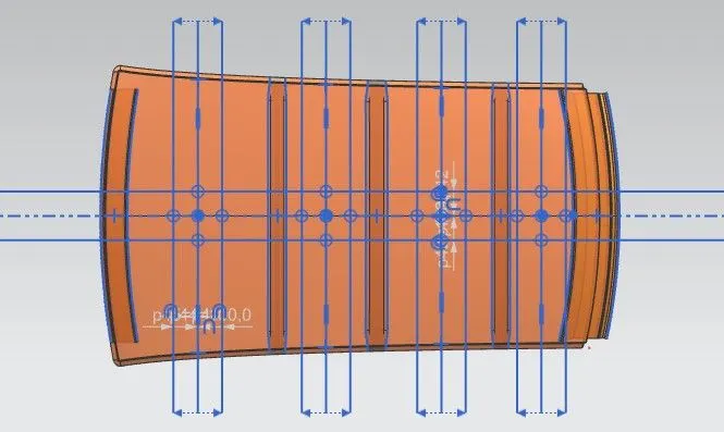
RX Value:
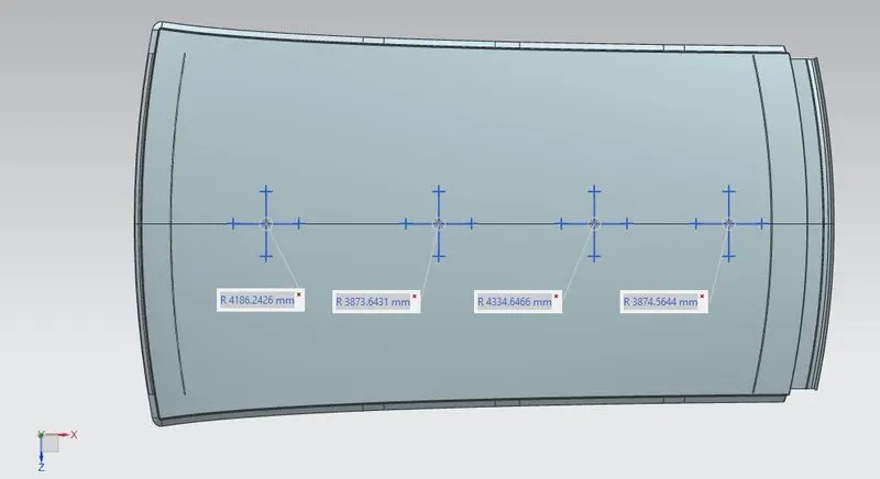
RY Value:
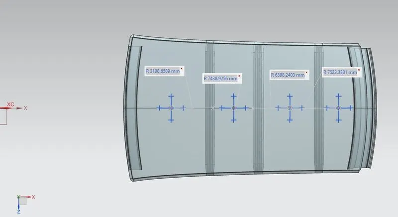
LY Value:
Roof Legth is =2029.2422
LX1,LX2 & LX3 Value: :
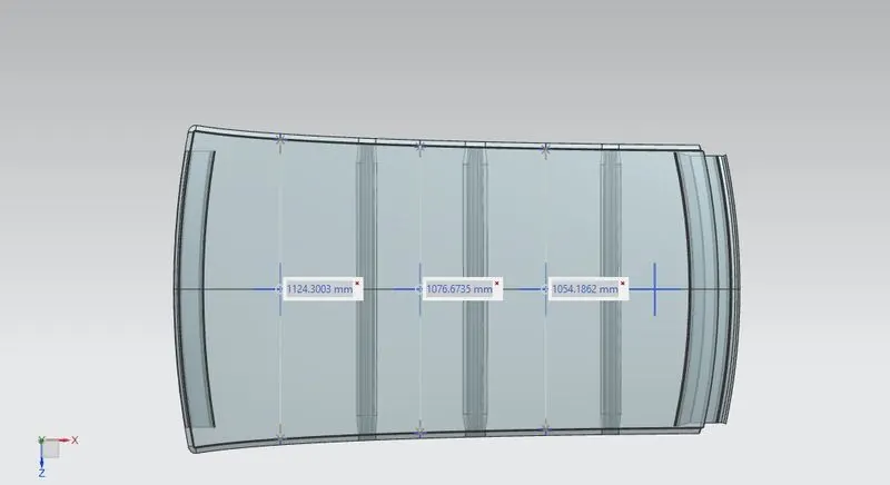
Iy = Geometrical moment of inertia of Roof BOW (Y cross-section )[mm4]
BOW ROOF 1
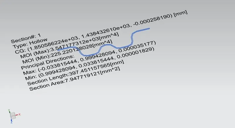
Moment of inertia maximum,( MAX) I max =3.547×10³ ( mm4)
Moment of inertia maximum ,( MIN) I min =225.22 ( mm4)
BOW ROOF 2
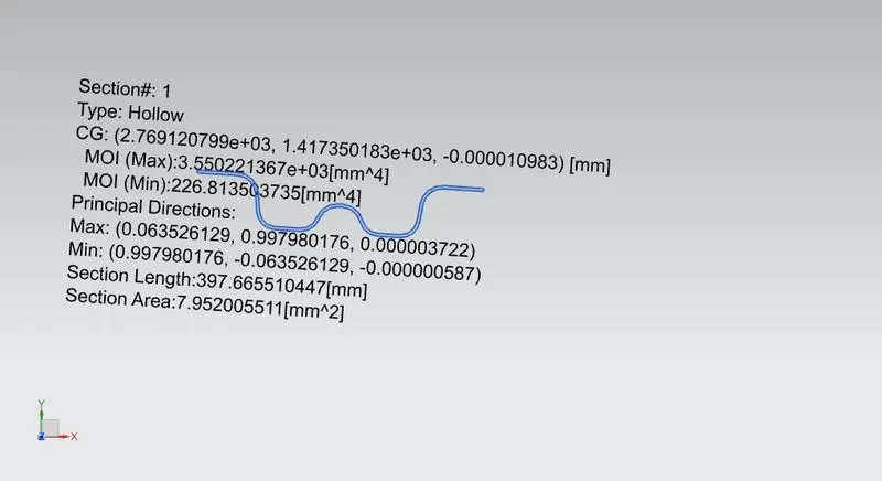
Moment of inertia maximum,( MAX) I max =3.55×10³ ( mm4)
Moment of inertia maximum ,( MIN) I min =226.813 ( mm4)
CENTRAL ROOF RAIL -
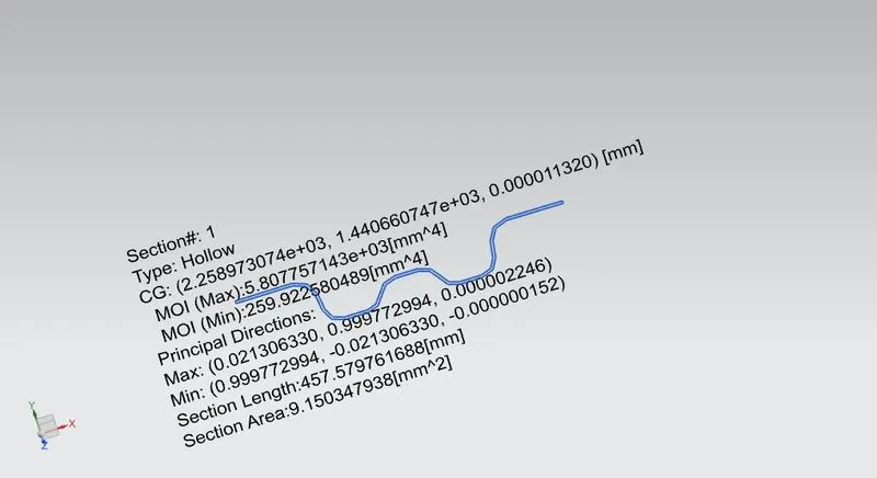
Moment of inertia maximum,( MAX) I max =5.807×10³ ( mm4)
Moment of inertia maximum ,( MIN) I min =259.922 ( mm4)
APPLY THE VALUES IN THE FORMULA :
In order to find the snow load criteria apply all the necessary values from the roof to the give formula

It is observed from the values that obtained values of QR > 3.1
Section Modulus analysis:
The moment carrying capacity of an object is directly dependent on geometrical property (I) and material property (E) of an object, which is collectively termed as flexural rigidity (EI). Geometry of an object plays an important role in load bearing capacity of an object which is indicated by moment of inertia of a section.
Therefore, section modulus is the predominant factor which evidences the strength of an object and is defined as the ratio of the moment of inertia of the object about its centroidal axis to the distance of the extreme fibers of the object from the neutral axis.
There are two types of section modulus we have,
- Elastic section modulus
- Plastic section modulus
Elastic modulus is defined as,
S = I/Y
S – Section modulus,
I – Second moment of area
Y – distance from the neutral axis to outer most fiber of the object.
Front Roof Rail -
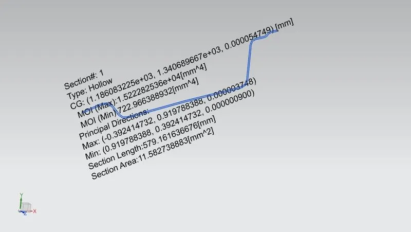
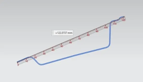
Moment of inertia (Max), Imax = 1.522 x 104 mm4
Moment of inertia (Min), Imin = 722.966 mm4
Section modulus = moment of inertia / distance between the neutral axis to extreme end of the object.
S = I/Y
Y = 61.036 mm
For maximum MOI,
S = 1.522 x 10⁴ /61.036
SMAX = 249.407 mm3
For minimum MOI,
S = 722.966 /61.036
SMIN = 11.845mm3
Rear Roof Rail -
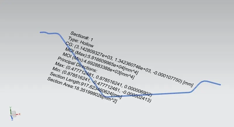
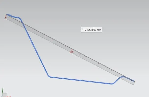
Moment of inertia (Max), Imax = 5.9166 x 104 mm4
Moment of inertia (Min), Imin = 4.692 x 104 mm4
Section modulus = moment of inertia / distance between the neutral axis to extreme end of the object.
S = I/Y
Y = 97.55 mm
For maximum MOI,
S = 5.9166 x 10⁴ /97.55
SMAX = 606.52 mm3
For minimum MOI,
S = 4.692 x 10⁴ /97.55
SMIN = 48.1074 mm3
Center Roof Rail -
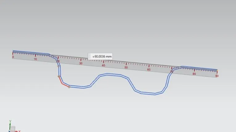
Moment of inertia (Max), Imax = 5.807 x 103 mm4
Moment of inertia (Min), Imin =259.9225 mm4
Section modulus = moment of inertia / distance between the neutral axis to extreme end of the object.
S = I/Y
Y = 45 mm
For maximum MOI,
S = 5.807 x 10³ /45
SMAX = 129.061 mm3
For minimum MOI,
S = 259.9225 /45
SMIN = 5.776 mm3
Bow Roof 1 -
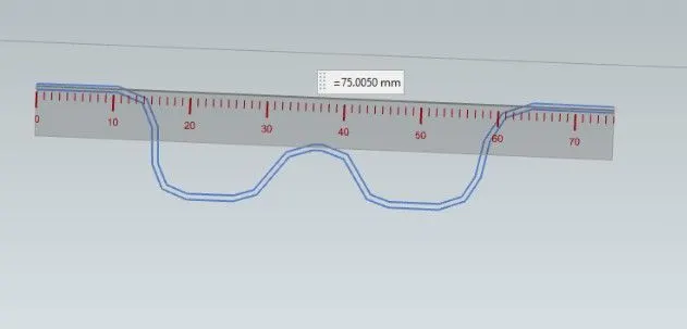
Moment of inertia (Max), Imax = 3.5471 x 103 mm4
Moment of inertia (Min), Imin =225.22 mm4
Section modulus = moment of inertia / distance between the neutral axis to extreme end of the object.
S = I/Y
Y = 37.5 mm
For maximum MOI,
S = 3.5471 x 10³ /37.5
SMAX = 94.591 mm3
For minimum MOI,
S = 225.22 /37.5
SMIN = 6.0058 mm3
Bow Roof 2 -
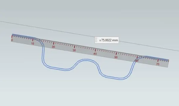
Moment of inertia (Max), Imax = 3.55 x 103 mm4
Moment of inertia (Min), Imin =226.81 mm4
Section modulus = moment of inertia / distance between the neutral axis to extreme end of the object.
S = I/Y
Y = 37.5 mm
For maximum MOI,
S = 3.55 x 10³ /37.5
SMAX = 94.672 mm3
For minimum MOI,
S = 226.81 /37.5
SMIN = 6.048 mm3
DRAFT ANALYSIS:
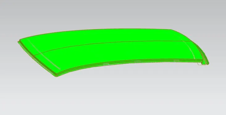
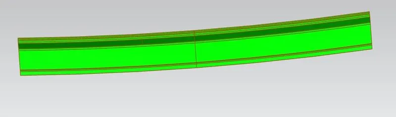
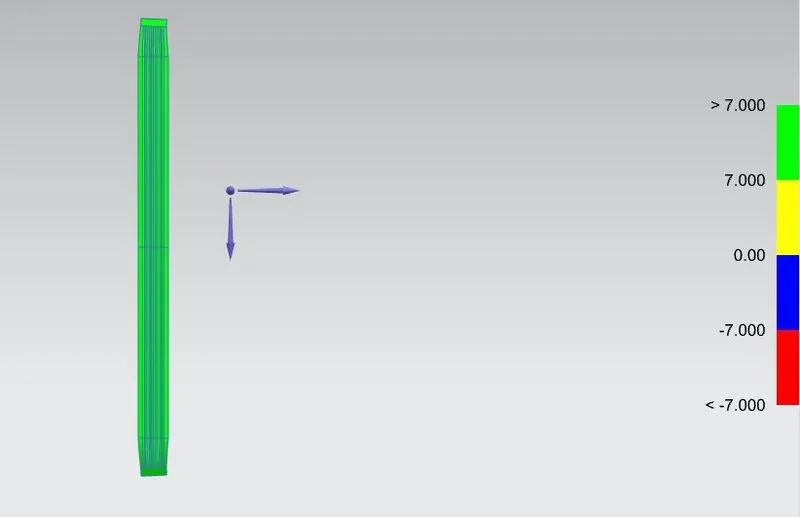
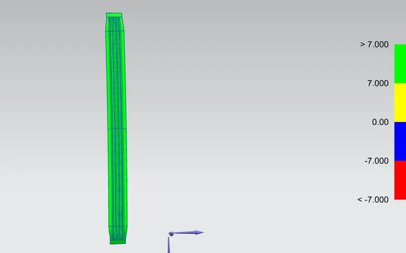
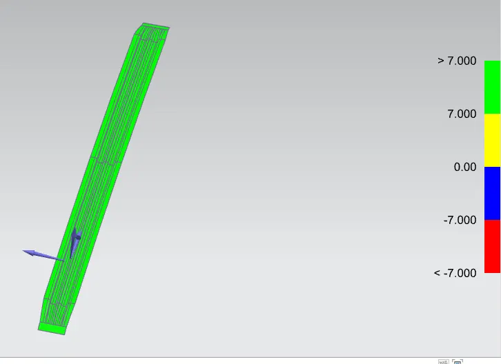
The Draft Analysis command enables you to detect if the part you drafted will be easily removed. This type of analysis is performed based on color ranges identifying zones on the analyzed element where the deviation from the draft direction at any point, corresponds to specified values.
Minimum draft angle of 7 degree is considered for analysis. Green colour show positive draft angle of the part more than 7 degree.
ROOF OUTER PANEL:
FRONT ROOF RAIL:
BOW ROOF 1 :
CENTER ROOF RAil :
BOW ROOF 2:
REAR ROOF RAIL:
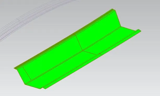
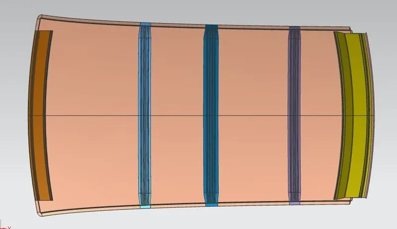
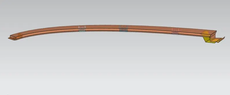
Pictrures of the roof design in all views -
TOP VIEW :
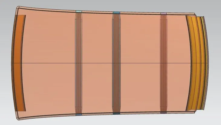
BOTTOM VIEW :
SIDE VIEW :
ISOMETRIC VIEW :
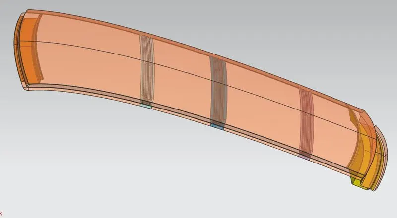
Conclusion:
- The car roof and its reinforcements were developed from the given styling surface and following the master sections provided.
- Curvature study on the roof and calculations are performed to determine the position of the Bow-roofs.
- Calculations for Snow load Criteria is done to check the durability of the Roof.
- Section Modulus Calculations are done to predict the amount of deformation and deflection of a part.
- Draft Analysis is done on the Roof & the Reinforcements designed for the minimum draft angle of 7 degrees.
Hence ,
By doing this above operations I have successfully designed a roof which has all the parameters and is designed according to the master sections and formulas provided to predict the position of bow roofs and Snow load criteria.