Roof Design
AIM :
To Create The Essential Flanges & Reinforcements For given Styling Roof.
Objectives :
Provide appropriate dimensions and check for Draft analysis.
Do a curvature study on the roof and perform calculations to determine the position of the Bow-roofs.
Suggest and implement remedies in the design if the criterion is not full-filling
Start with the creation of a roof ditch area with a tool opening angle of 7 degrees.
Develop the reinforcements as separate parts
Bow–Roof Prediction Formula
W = [1.73 x 10^(-3) x L] + [1.85 x 10^(-8) x (R^2)/t] + [ 1.10x10^(-3) x l] - 2.68
Where,
L = Roof Length in X-Direction[mm](Roof dimension in 0-Y)
R = Roof curvature
R = 2(Rx*Ry)/(Rx+Ry)
Rx = X curvature
Ry = Y curvature
t = Roof plate thickness [mm]
l = Bow Roof Span [mm]
Judgment Condition
OK< 2.7
Snow Load Prediction Formula
Qr = [Iy x t2] / [α x s x [(Rx + Ry)/2]2 x 10-8]
Note: The Qr value given over here is correct. There was a typo error in the formula given in the video.
Where,
α = My x Lx2 x 10-12 , My = Y(Ly-Y)
t = Roof plate thickness [mm]
Ly = Distance between the front and rear roof Rails on the Vehicle along with 0Y[mm]
Length of Roof panel with the center point between Roof rail Front /Rear as the front and rear reference point.
Lx = Distance between the Left and Right end of the roof on the Roof BOW [mm]
The width of the roof panel is exposed on the surface.
Y = Distance front Front Roof Rail to Roof BOW[mm]
s = Distance for which Roof BOW bears divided load [mm]
s = L1/2 + L2/2
Iy = Geometrical moment of inertia of Roof BOW (Y cross-section )[mm4]
Rx = Lateral direction curvature radius of roof panel Y cross-section on Roof BOW [mm]
Roof panel curvature Radius of the Length Lx in Front view
Ry = Longitudinal Direction curvature radius of the Roof panel X cross-section on Roof BOW [mm]
Roof panel X curvature radius of length s in Side view
Judgment condition
Qr ≥ 3.1
250 ≤ s ≤ 380
Here are some Reference images for the Master sections - These images are just to give you a brief idea about the design.
Procedure :
An automobile roof or car top is the portion of an automobile that sits above the passenger compartment, protecting the vehicle occupants from sun, wind, rain, and other external elements. Because the earliest automobiles were designed in an era of horse-drawn carriages, early automobile roofs used similar materials and designs.
a car with a foldable or removable roof is called a convertible car. Such cars can transform from a roof-top model to an open-top model within a few minutes. The roof can be a hard or soft top. Open-top cars are also called cabriolets or drop-top cars.
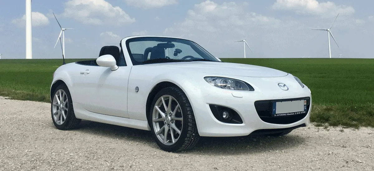
Car roof rails not just enhance your vehicle's appearance but are also useful to carry bulky cargo or sporting equipment. Special roof mounts can be fixed to these car roof rails to take heavy items on your road trips. When on a road trip with friends, you require space to carry your luggage.

A hardtop is a rigid form of automobile roof, which for modern cars is typically constructed from metal. A hardtop roof can be either fixed (i.e. not removable), detachable for separate storing or retractable within the vehicle itself.
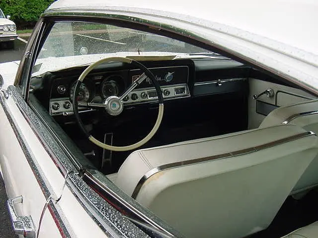
STYLING ROOF :
Open The Nx Cad Create The Assembly& Add The Styling Roof Into The Catia. As Shown in figure given below :
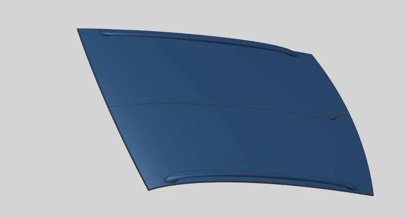
Then Add Multiple Part Components & Named It as Outer Roof, Inner Roof, Bow Roof Centre Roof Etc..,
OUTER ROOF :
Soo Activate The Outer Roof & Extract The Face As Shown in figure given below.
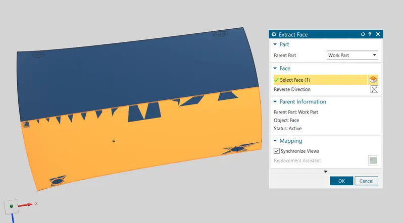
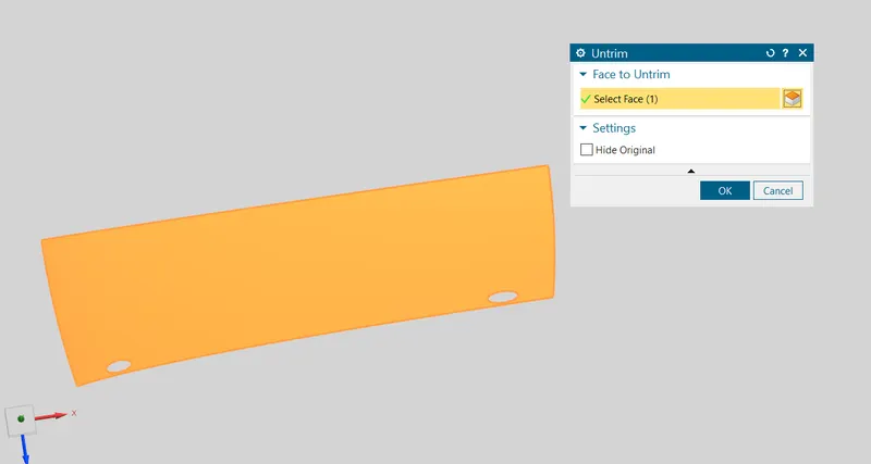
Then Untrim Properly As Shown in figure given below.
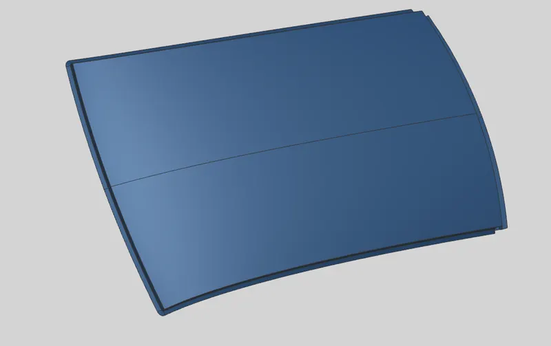
Use The Law Extension To & Other Commands Create Outer The Rear Roof Propely As Wells Side Bodies & Mirror the Geometry As Shown in figure given below.
INNER ROOF :
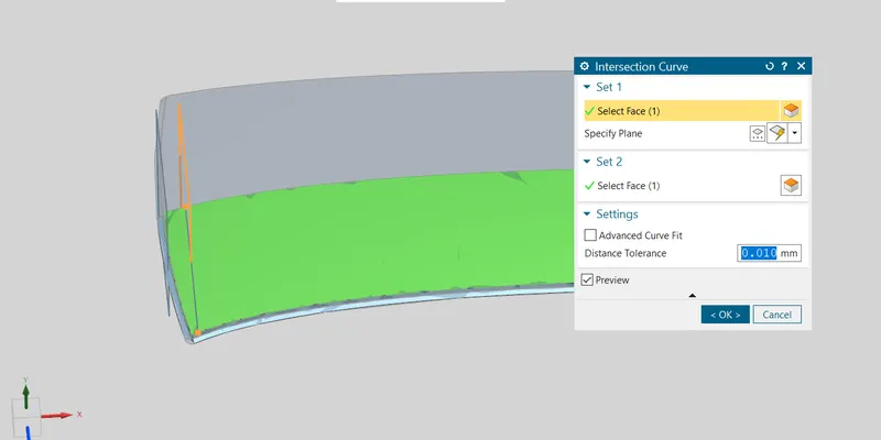
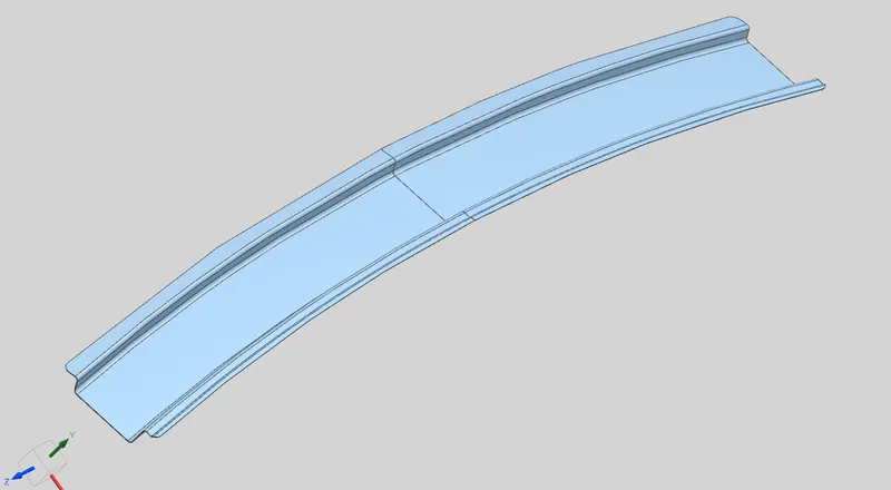
Take The Plane & Add intersection Curve as shown in figure given below.
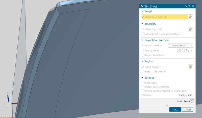
Trim the sheet as shown in figure given below.
Then Thicken The Sheet As shown in figure given below.
BOW ROOF :
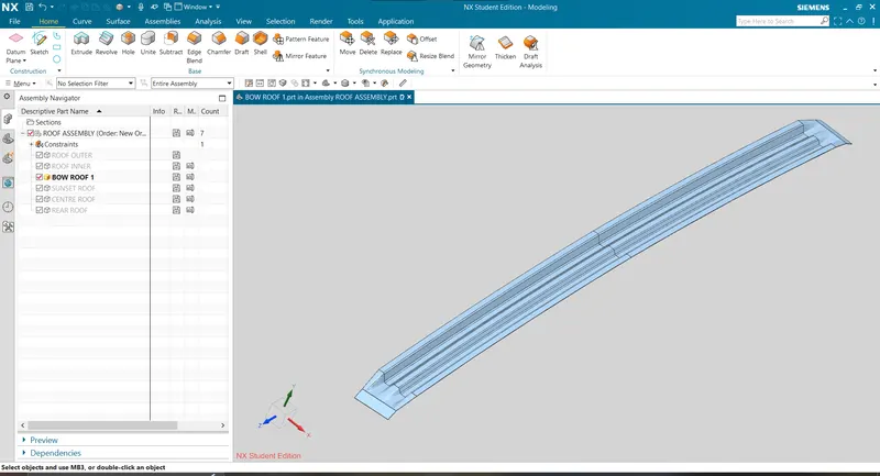
Follow The Same Procedure like Taking The Intersection & Offsetting the surfaces according to the master section & Trim Properly As Shown in figure given below.
SUNSET ROOF :
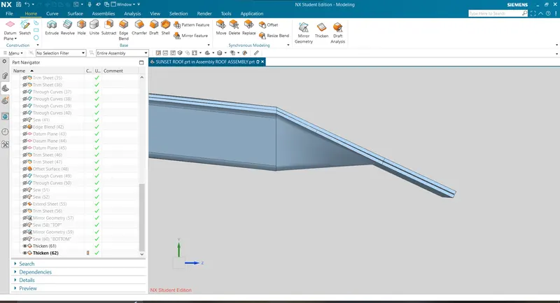
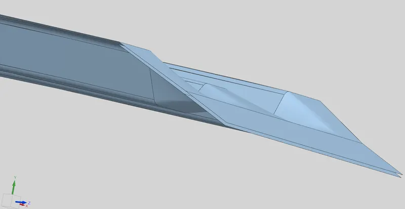
Taking The Intersection & Offsetting the surfaces according to the master section & Trim Properly As Shown in figure given below.
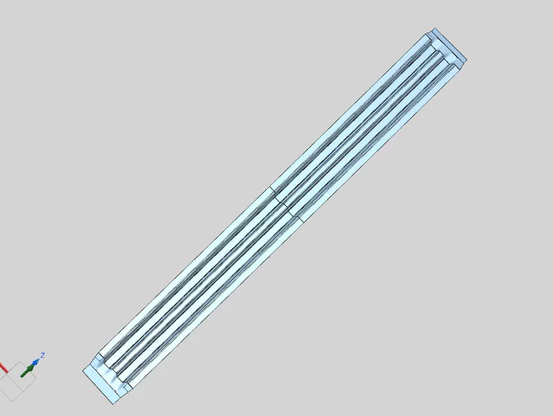
CENTER ROOF :
Follow The Same Procedure like Taking The Intersection & Law Extension After that Offsetting the surfaces according to the master section & Trim Properly As Shown in figure given below.
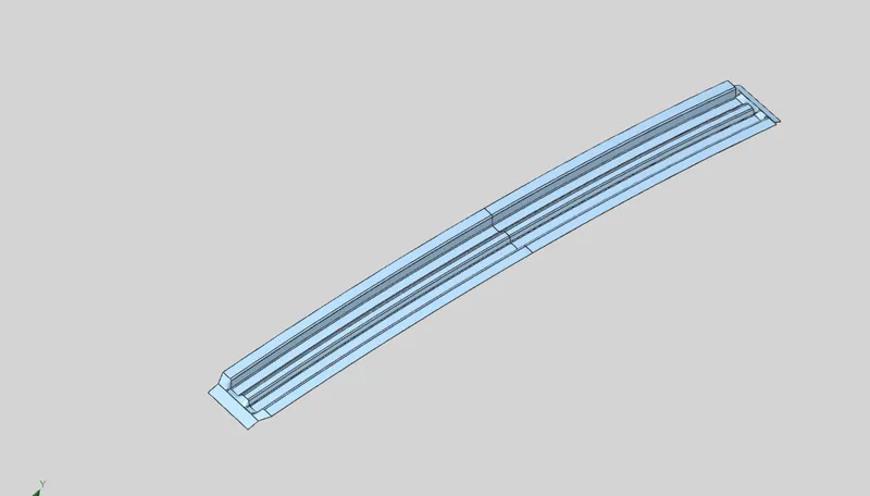
REAR ROOF :
Follow The Same Procedure like Taking The Intersection & Law Extension After that Offsetting the surfaces according to the master section & Trim Properly As Shown in figure given below.
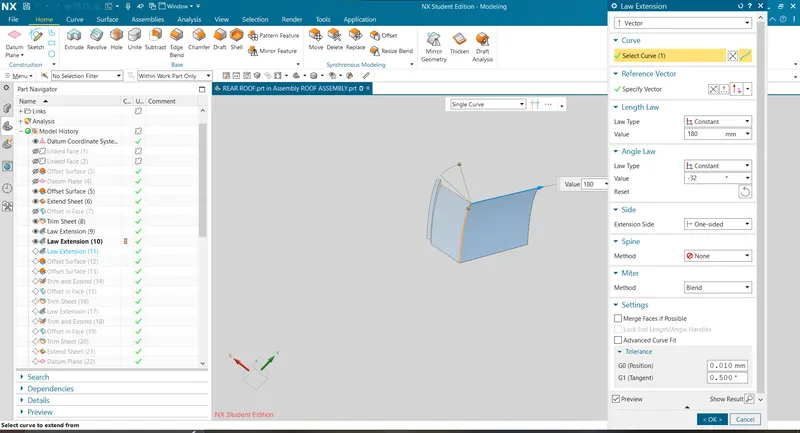
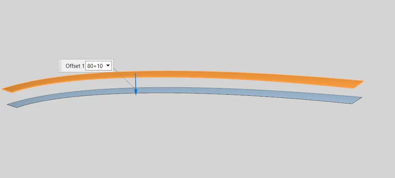
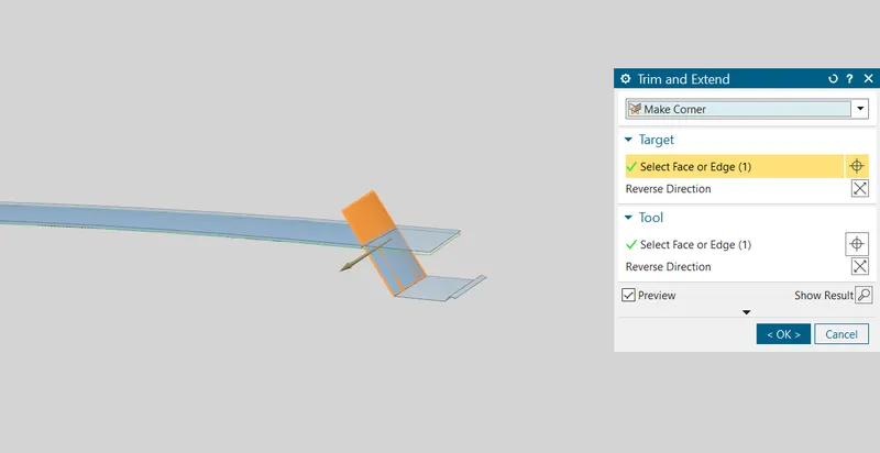
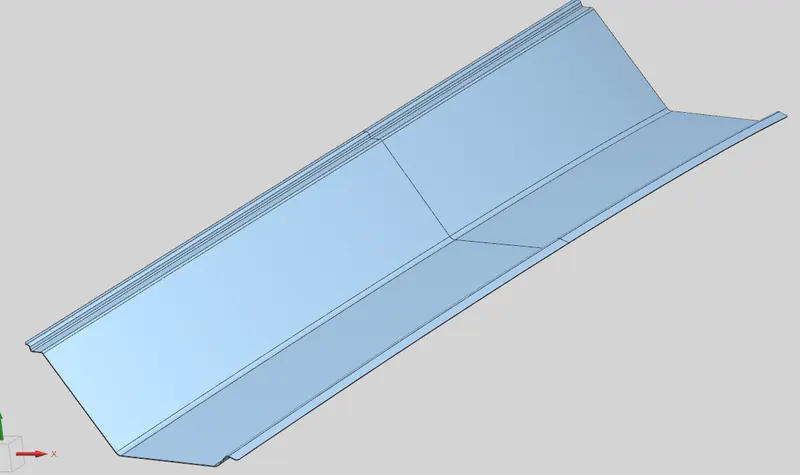
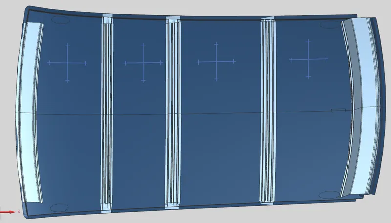
After Thickening The Roof Different Type Of Views As Shown in figure given below :
TOP VIEW :
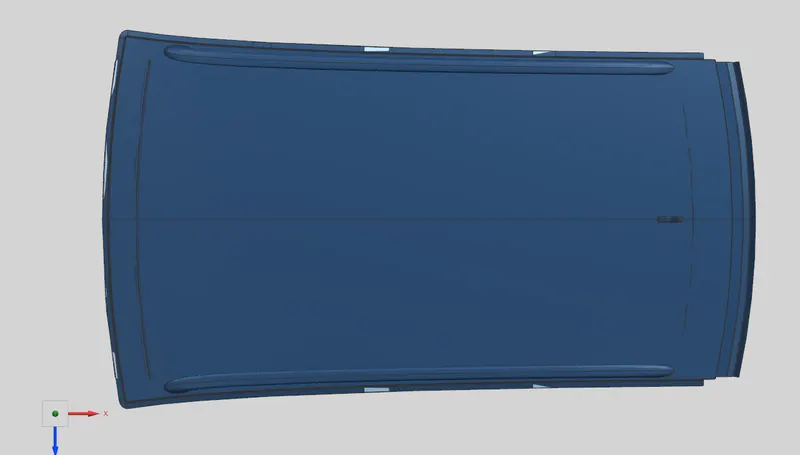
BOTTOM VIEW :
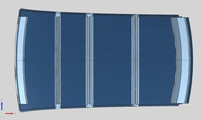
LEFT VIEW :
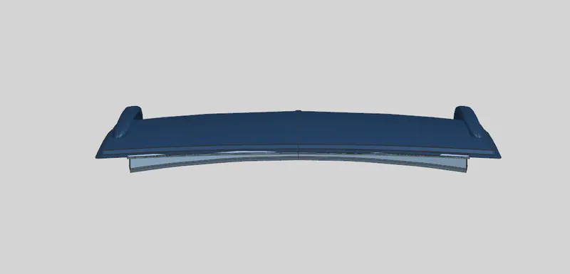
RIGHT VIEW :
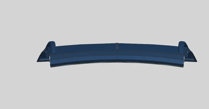
ISOMETRIC VIEW :
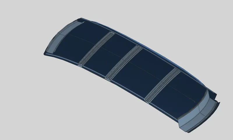
CURVATURE STUDY ON THE ROOF:
- Heat Distortion
- Snow Load
HEAT DISTORTION:
The heat distortion study plays an important role in Sheet metal application. Heat distortion is a temperature limit above which material cannot be used for structural application. This study is useful to find where the material starts to soften when exposed to a fixed load at elevated temperatures. In order to avoid bending, damage to the roof is based on the heat distortion temperature. This study will provide which position of the bow roof gives enough strength to the roof.
Formula -
W = [1.73 x 10^ (-3) x L] + [1.85 x 10^ (-8) x (R^2)/t] + [1.10x10^ (-3) x l] - 2.68
Judgement Condition: OK< 2.7> 3.1
Where,
L = Roof Length in X-Direction [mm] (Roof dimension in 0-Y)
R = Roof curvature
R = 2(Rx*Ry)/(Rx+Ry)
R = X curvature
Ry = Y curvature
t = Roof plate thickness [mm]
l = Bow Roof Span [mm]
|
Roof POSITION |
Rx |
Ry |
R |
l |
L |
t |
R2/2 |
W |
|
FRONT ROOF |
14856.468 |
3277.15824 |
5369.802584 |
392.028 |
2028.213 |
0.75 |
14417389.9 |
1.568846392 |
|
BOW ROOF |
10705.55 |
3968.044 |
5790.00529 |
361.21 |
2028.213 |
0.75 |
16762080.63 |
1.684517801 |
|
CENTER ROOF- BOW ROOF REAR |
6822.69 |
4820.55 |
5649.478715 |
380.948 |
2028.213 |
0.75 |
15958304.88 |
1.644864864 |
|
REAR ROOF |
2830.52 |
5765.805 |
3797.024047 |
489.137 |
2028.213 |
0.75 |
7208695.805 |
1.213217483 |
From the above table,, we conclude that all the values are W< 2.7 and also W> 3.1. So that all bow roof areas are placed in the right place.
Snow Load Criteria-
The snow load criteria study is used to check the durability of the roof to withstand the snowfall on the roof and reflex it is an original shape without any permanent deformation after the load is removed.
Formula -
Qr = [Iy x t2] / [α x s x [(Rx + Ry)/2]2 x 10-8]
Note: The Qr value given over here is correct. There was a typo error in the formula given in the video.
Where
α = My x Lx2 x 10-12, My = Y(Ly-Y)
Judgement condition = Qr ≥ 3.1
250 ≤ s ≤ 380
t = Roof plate thickness [mm]
Ly = Distance between the front and rear roof Rails on the Vehicle along with 0Y[mm]
Length of Roof panel with the center point between Roof rail Front /Rear as the reference point of the front and the rear.
Lx= Distance between the Left and Right end of the roof on the Roof BOW [mm]
The width of the roof panel is exposed on the surface.
Y = Distance front Front Roof Rail to Roof BOW [mm]
s= Distance for which Roof BOW bears divided load [mm]
s = L1/2 + L2/2
Iy = Geometrical moment of inertia of Roof BOW (Y cross-section) [mm4]
Rx = Lateral direction curvature radius of roof panel Y cross-section on Roof BOW [mm]
Roof panel curvature Radius of the Length Lx in Front view
Ry = Longitudinal Direction curvature radius of the Roof panel X cross-section on Roof BOW [mm]
RX & RY (X & Y Curvature):
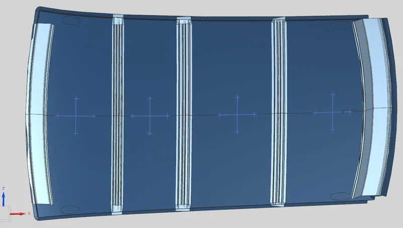
at 0-Y axis on a perpendicular plane to the roof. Draw 100 mm lines offset to either side of the 0-Y axis line. Now the center lines are drawn between each adjacent roof rail respectively. Intersection points are marked in the sketch. Make all the geometry in construction lines except points.
Project intersection points in the sketch are projected to the roof surface.
Join the project points using an arc curve and measure the radius value using the minimum radius comment.
|
Roof POSITION |
Iy |
My |
α |
Lx |
Ly |
Y |
L1 |
L2 |
S |
Rx |
Ry |
t |
Qr |
|
FRONT ROOF - BOW ROOF FRONT |
2094 |
647709.166 |
0.726146612 |
1058.82 |
2044.21 |
392.034 |
392.034 |
361.223 |
376.6285 |
3968.05 |
16612.28 |
0.75 |
4.07 |
|
BOW ROOF FRONT-CENTER ROOF |
6587 |
607933.6131 |
0.70000466 |
1073.056 |
2044.21 |
361.223 |
361.223 |
361.223 |
361.223 |
4283.27 |
11188.6 |
0.75 |
24.49 |
|
CENTER ROOF- BOW ROOF REAR |
4913 |
633647.1073 |
0.762607535 |
1097.051 |
2044.21 |
380.972 |
361.223 |
380.972 |
371.0975 |
3805.85 |
6749.42 |
0.75 |
35.06 |
If the roof structure passes to the snow load condition.
Qr > 3.1
So, we did the curvature study on the roof. Heat distortion and snow load condition, my roof passes the two criteria, so the position of bow roofs and center reinforcement roofs are placed in the right area.
Draft analysis-
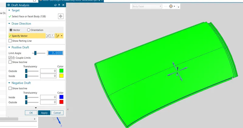
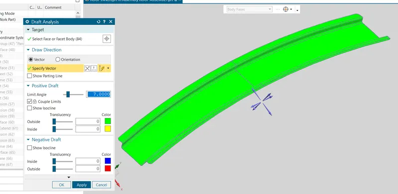
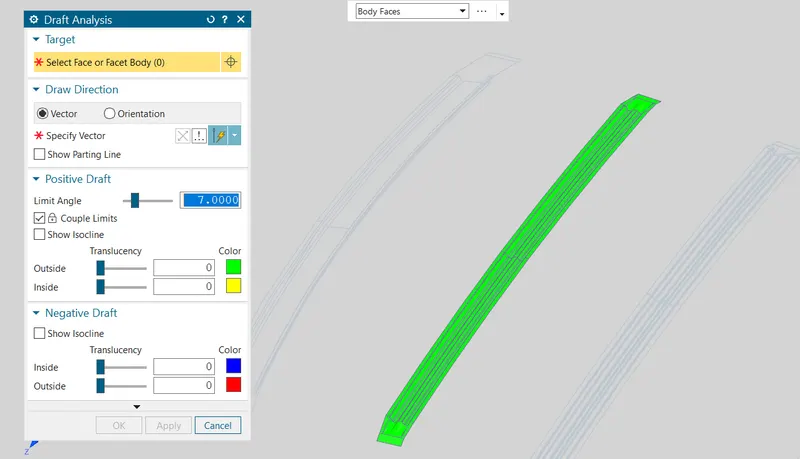
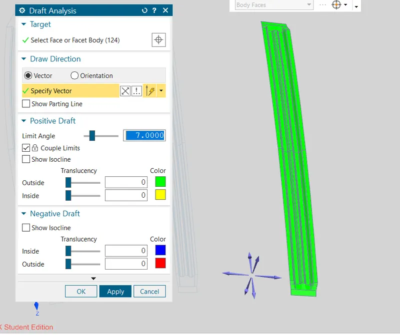
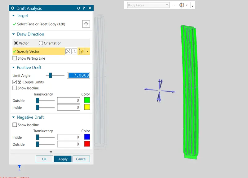
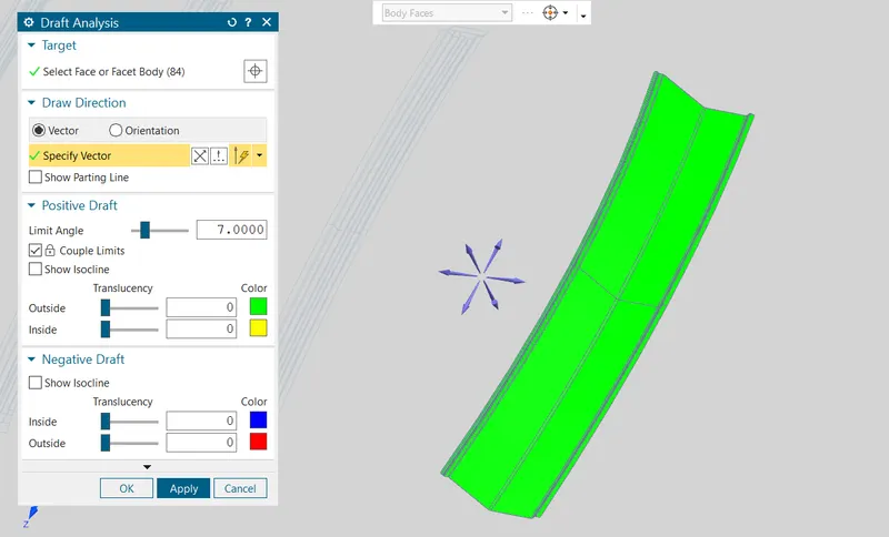
The Draft Analysis command enables you to detect if the part you drafted will be easily removed. This type of analysis is performed based on color ranges identifying zones on the analyzed element where the deviation from the draft direction at any point, corresponds to specified values.
A minimum draft angle of 70 is considered for analysis. green color infers on the parts that all face along the tooling direction has a positive draft angle greater than 70 and passed in analysis.
OUTER ROOF :
INNER ROOF :
BOW ROOF :
SUNSET ROOF :
CENTRE ROOF :
REAR ROOF :
CONCLUSION :
Hence the roof, front roof rail, bow roof rail, central roof rail, and rear roof rail are designed by following the master sections, and the moment of inertia, section modulus, and draft analysis is carried out to check the feasibility of manufacturing.