Roof Design
INTRODUCTION
The roof of a car or other vehicle is the top part of it, which protects passengers or goods from the weather. The roof also protects the passenger from any injury when the car gets crashed or is rolled over or something heavy falls on the roof.
AIM:
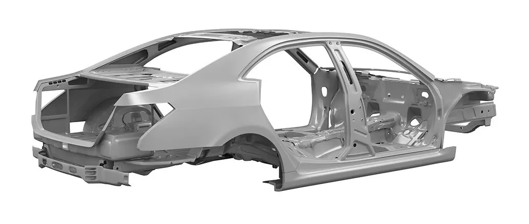
1.Main objective of the project is to create the Roof Sheetmetal design in NX cad, and also designing Front roof rail, rear roof rail, bow roof front, bow roof rear, center roof rail and Reinforcement are creating to build the strong roof.
2.Do curvature study on Roof and performance calculations for Heat distortion and Snow load criteria to determine the position of the Bow roofs.
3.Finding the moment of inertia and section modulus for Bow-roofs and center roof rail.
4.And, also finding the Draft Analysis of each part.
DESCRIPTION:
An automobile roof or car top is the portion of an automobile that sits above the passenger compartment, protecting the vehicle occupants from sun, wind, rain, and other external elements. When it is seeing from outside of the car, it is just closing the top portion. But in design point of view, it is hard to create the design. Because of you have to create no of support rails for enough strength to withstand the load. Bow roofs are primarily fixed in flatter region to enhance strength. Front roof and rear roof rails are fixed to the ditch area using spot weld operation. But front, rear bow roof and center roof rails are fixed to roof using mastic sealants. We don’t want so much gap between roof rails and bow roof area. So, we reducing the NVH issues.
METHODOLOGY:
We get the model of the roof of the from the styling team. Then we will have to do all the engineering work. We create the ditch area for the roof and also the roof bows and roof rails for the roof which would we designed by us considering all the safety norms and regulations.
ROOF CRASH TEST:
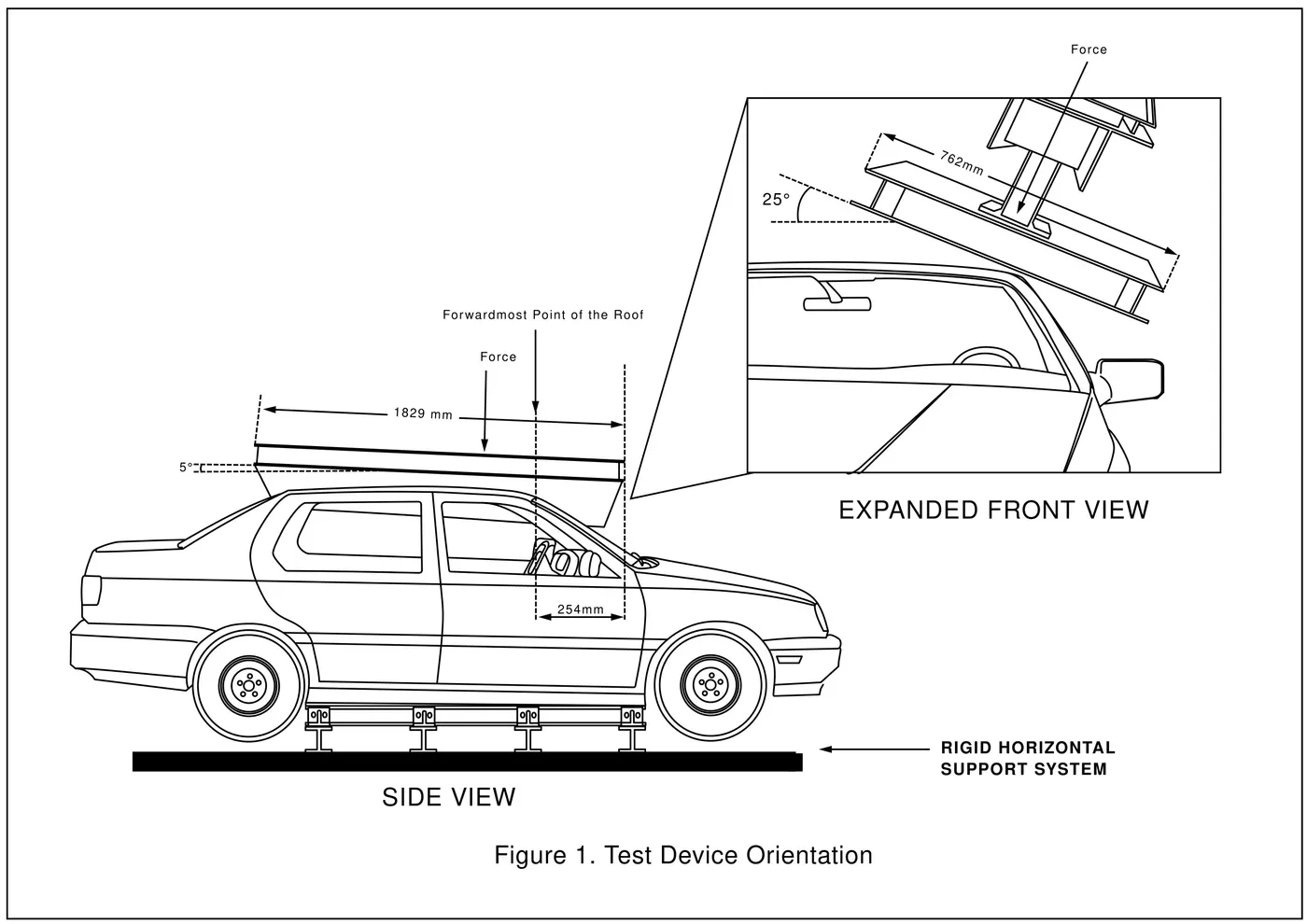
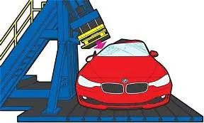
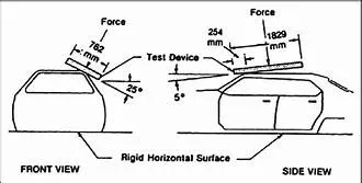
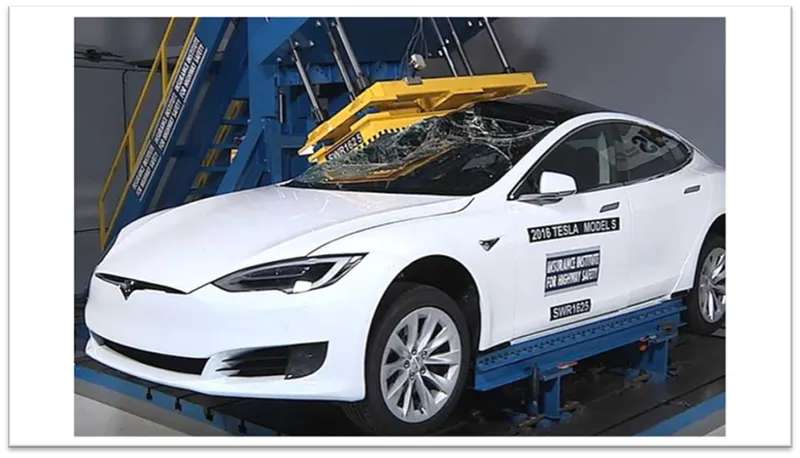
To perform a roof crush test, the vehicle or body-in-white is mounted on the rig bedplate, supported along the sills and chassis frame. The loading platen, held at the regulation requirement angles, is lowered onto the roof structure. It is then loaded to the specified force based on the unloaded mass of the vehicle.
TEST VEHICLE PREPARATION:
With the vehicle on a level surface, the on-road pitch angle at the front door sill is measured on both sides of the vehicle. Unless the vehicle manufacturer requests otherwise, roof racks and other nonstructural items that may be contacted during the test are left as installed from the factory.
Any trim or other components are removed if they interfere with supporting the vehicle along its rocker panels. For vehicles with vertical pinch weld flanges on the bottom of the rocker panels, the vehicle support system consists of one I-beam (HR A-36 W4X13) for each rocker panel.
Each I-beam has a clamping system incorporated on the top that is tightened against the pinch weld flange to clamp the system in place (Figures 1 and 2). When the pinch weld flange has a bend that prevents supporting the sill with one I-beam, more than one I-beam can be used on each side of the vehicle.
For vehicles with no pinch weld flange, or with a nonvertical flange angle that precludes clamping, mounting by another method may be necessary, such as that described in the National Highway Traffic Safety Administration’s Laboratory Test Procedure (2006).
Prior to testing, the front-row seat back on the side being tested is reclined to prevent interaction with the crushing roof. Rear seats are latched in their upright position. All windows are closed and doors are locked.
ROLL OVER CRASH TEST:
If two vehicles have the same star rating, a consumer can compare the Chance of Rollover percentage between the two vehicles. The vehicle with the lower the percentage is less likely a vehicle is to rollover- this percentage is based both on the static stability factor (SSF) and if the vehicle tips up during the dynamic test.
What are the chances a Vehicle will roll? The rollover resistance rating is an estimate the risk of rolling over in a single-vehicle crash As the chart below indicates, the lowest-rated vehicles (1 star) are at least four times more likely to roll over than the highest rated vehicles (with 5 stars) when involved in a single-vehicle crash.
5 stars Has a risk of rollover of less than 10%
4 stars Has a risk of rollover between 10% and 20%
3 stars Has a risk of rollover between 20% and 30%
2 stars Has a risk of rollover between 30% and 40%
1 star Has a risk of rollover greater than 40%
DIFFERENT MATERIALS USED IN THE MAKING OF CAR:
There are several materials used to make our cars which we can see, touch and feel. But there are some which we do not see yet contribute significantly for the vehicle to function as intended by the manufacturer. The main materials used for making cars and their parts are steel, aluminum, magnesium, copper, plastics, composites, rubber, glass, fabric/leather and a few more. These materials have been around for quite some time but have evolved greatly and diversely. For example, we call the shell of the vehicle as BIW (body in white) and everyone would assume steel or aluminum in the past, but now the naming BIW might imply the shell (as per automotive jargon) be made using Carbon fiber.
The main factors for material selection, especially for the body include thermal, chemical, or mechanical, environmental resistance, durability, ease of assembly and manufacturing. Affordability is an important consideration in vehicle design, which includes factoring in the costs associated with a car’s complete life cycle, including producing, running and scrapping costs which are mostly controlled via regulations at least in Europe. The automotive sector is constantly pushed by the governmental policies to reduce carbon emissions, improve the fuel efficiency simultaneously increasing passenger and road user safety. One solution for the manufacturer is to achieve this is via material selection and optimization. There are separate departments under advanced research in every OEM, testing and suggesting new materials to be used on the cars.
COMPONENTS OF ROOF:
OUTER PANEL
FRONT ROOF RAIL
CENTER ROOF RAIL
REAR ROOF RAIL
BOW ROOFS
SECTION VIEW OF REAR ROOF
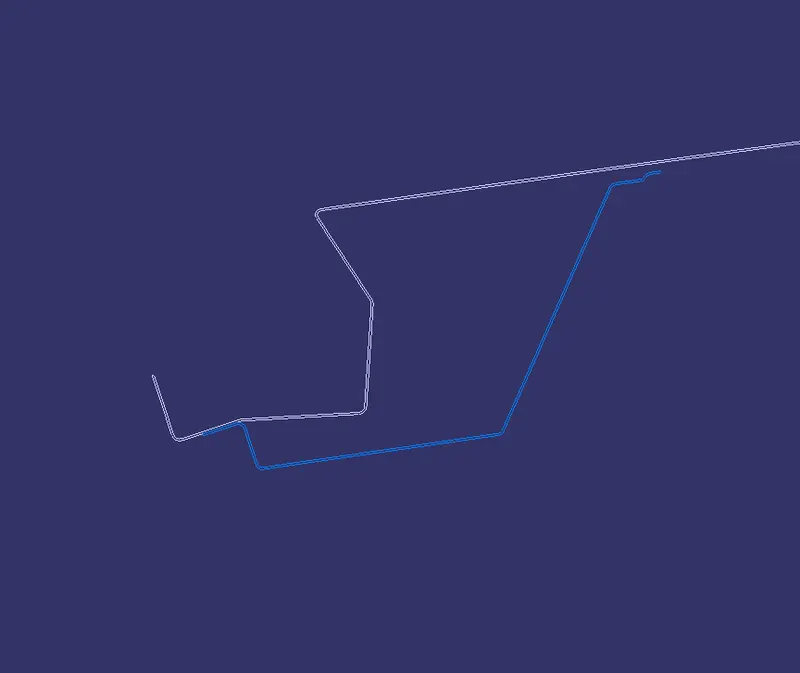
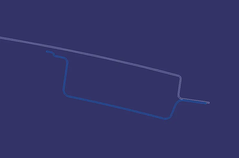
SECTION VIEW OF FRONT ROOF
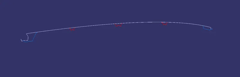
SECTION VIEW OF HOOD
SPOT WELDING:
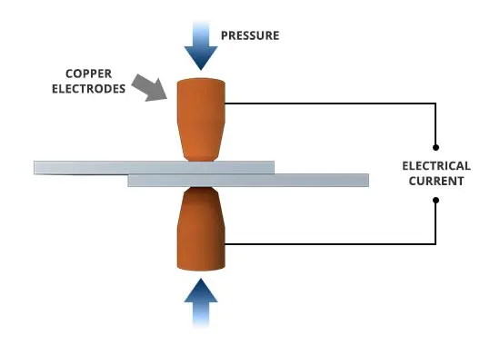
How Does Spot Welding Work?
A form of resistance welding, spot welding is one of the oldest welding processes whereby two or more sheets of metal are welded together without the use of any filler material.
The process involves applying pressure and heat to the weld area using shaped alloy copper electrodes which convey an electrical current through the weld pieces. The material melts, fusing the parts together at which point the current is turned off, pressure from the electrodes is maintained and the molten “nugget” solidifies to form the joint.The welding heat is generated by the electric current, which is transferred to the workpiece through copper alloy electrodes. Copper is used for the electrodes as it has a high thermal conductivity and low electrical resistance compared to most other metals, ensuring that the heat is generated preferentially in the work pieces rather than the electrodes.
The amount of heat depends on the thermal conductivity and electrical resistance of the metal as well as the amount of time the current is applied. This heat can be expressed by the equation:
Q = I2Rt
In this equation “Q” is heat energy, “I” is current, “R” is electrical resistance and “t” is the time for which the current is applied.
Where is Spot Welding Used?
Spot welding has applications in a number of industries, including automotive, aerospace, rail, white goods, metal furniture, electronics, medical building and construction.
Given the ease with which spot welding can be automated when combined with robots and manipulation systems, it is the most common joining process in high volume manufacturing lines and has in particular been the main joining process in the construction of steel cars for over 100 years.

CALCULATION
BOW ROOF CALCULATION:
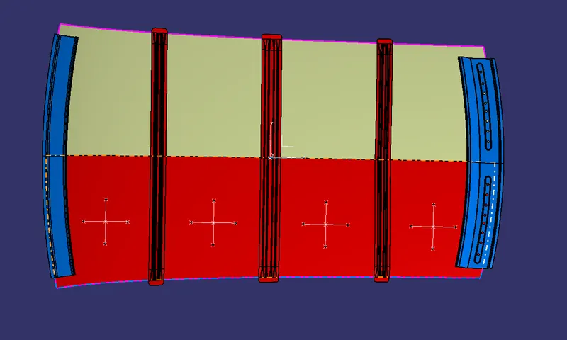
Bow–Roof Prediction Formula
W = [1.73 x 10^(-3) x L] + [1.85 x 10^(-8) x (R^2)/t] + [ 1.10x10^(-3) x l] - 2.68
Where,
L = Roof Length in X-Direction[mm](Roof dimension in 0-Y)
R = Roof curvature
R = 2(Rx*Ry)/(Rx+Ry)
Rx = X curvature
Ry = Y curvature
t = Roof plate thickness [mm]
l = Bow Roof Span [mm]
Judgment Condition
OK< 2.7

THE W<2.7
THE BOW ROOF IS SAFE SINCE IT COMES UNDER THE JUDGEMENT CONDITION
SNOW LOAD CALCULATION
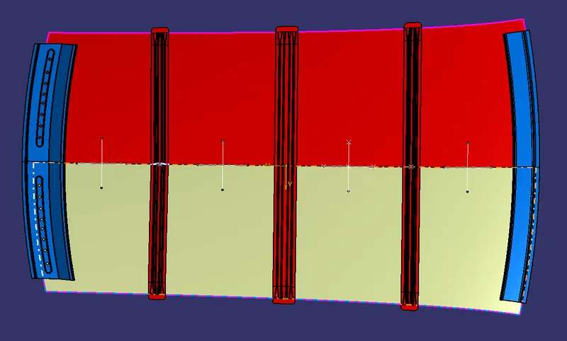
Snow Load Prediction Formula
Qr = [Iy x t2] / [α x s x [(Rx + Ry)/2]2 x 10-8]
Note: The Qr value given over here is correct. There was a typo error in the formula given in the video.
Where,
α = My x Lx2 x 10-12 , My = Y(Ly-Y)
t = Roof plate thickness [mm]
Ly = Distance between the front and rear roof Rails on the Vehicle along with 0Y[mm]
Length of Roof panel with the center point between Roof rail Front /Rear as the front and rear reference point.
Lx = Distance between the Left and Right end of the roof on the Roof BOW [mm]
The width of the roof panel is exposed on the surface.
Y = Distance front Front Roof Rail to Roof BOW[mm]
s = Distance for which Roof BOW bears divided load [mm]
s = L1/2 + L2/2
Iy = Geometrical moment of inertia of Roof BOW (Y cross-section )[mm4]
Rx = Lateral direction curvature radius of roof panel Y cross-section on Roof BOW [mm]
Roof panel curvature Radius of the Length Lx in Front view
Ry = Longitudinal Direction curvature radius of the Roof panel X cross-section on Roof BOW [mm]
Roof panel X curvature radius of length s in Side view
Judgment condition
Qr ≥ 3.1
250 ≤ s ≤ 380

CONCLUSION:
FOR HEAT DISTORTION
*THE BOW ROOF IS SAFE SINCE IT COMES UNDER THE JUDGEMENT CONDITION
*THE DESIGN IS SAFE
*BOW ROOFS ARE ENOUGH TO SUPPORT THE ROOF
FOR SNOW LOAD CONDITION:
*THE GIVEN CONDITION Qr>3.1 IS NOT SATISFIED
*HENCE IT IS NOT SUITABLE FOR SNOW FALL REGION AS THE ROOF MAY FACE BEND DUE TO SNOW LOADING.
*IN ORDER TO SATISFY THE CONDITION THE BOW ROOF DESIGN CAN BE CHANGED IN THE FOLLOWING WAYS LIKE INCREASING THE EMBOSS DISTANCE CHANGING THE SHAPE OF ROOF SO THAT THE INERTIA VALUE WILL BE GREATER,INCREASING THE THICKNESS OF THE BOW ROOF
*ADDING EMBOSS TO THE OUTER ROOF SO THAT WE CAN MAKE THE ROOF STRONG