Roof Design
Roof challenge
- OBJECTIVE-
- To design the automotive roof styling surface by given skin data and prepare the assembly model to check the manufacturability & feasibility of the design.
- To perform the section modulus study for the prepare components for front roof rail, Bow roofs & rear roof rail.
- To create the ditch area & perform the draft analysis of the created model.
- INTRODUCTION OF ROOF
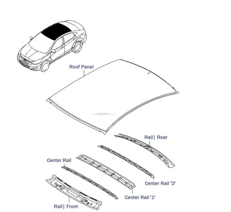
An Automobile roof is the top-most portion that sits above the passenger component to protects the vehicle occupants from sun, wind, rain & other external elements.
From the perspective view on styling surface of the roof externally, it looks simple but there are many components under the roof to give the agility, stability & strength. There is reinforcement structure/support which is added to the roof according to the shape & size of the vehicle. In some cases, to strengthen the roof-top, emboss is given locally. The components which used under the roof to give the strengthen are front roof rails, bow roofs with ditch area, centre bow roof area & rear roof rails. Mastics & spot welded the roof flange & ditch helps in strengthen the roof but also improve the NVH of the roof.
DESIGN CONSIDERATION OF ROOF
- Visibility criteria
- Head clearance
- Heat distortion & Snow load criteria
- Curvature study
- Safety parameters
- Draft Analysis
ROOF CRUSH TEST
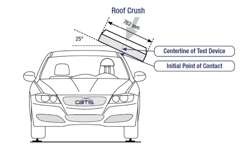
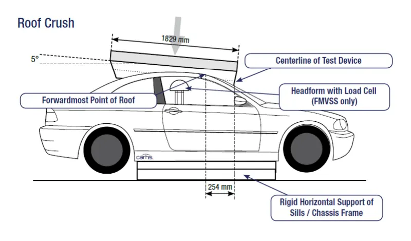
From safety point of view, vehicle roof plays crucial role for rollover accident & it is conducted by the organization, Insurance Institute of Highway Safety (IIHS). This organization has observed lot of road accidents of the vehicle has which has led to sustain injuries of occupants in the vehicle or sometime fatal injuries like severe head injuries, spinal injuries etc. To study the nomenclature of the roof design by the manufacturer’s, they have introduced roof crush test & roll-over test to study the protrusion of the damage roof & give standards to the improve the integrity of it.
For the test, the passenger shall be rigidly positioned on the horizontal surface with doors locked & window closed. A flat rectangular block surface of (762mm*1829mm) is placed below the roof surface on the vehicle. The block is inclined towards 5-degree angle on the frontal portion of the roof which is given a pressured of 5000lbs (22224N). The indentation caused by given pressure is been studied & analyse on the roof of the vehicle.
The lateral axis or the roll of the plate is such that it forms a 25-degree outboard angle with a horizontal surface as viewed from the front of the passenger car.
So IIHS, inspect every manufacturer roof crush test to check the vehicle is safety for the inside occupants. This type is test is mandatory & manufacturer keep in their mind to create a sheet design models which safe for the occupants.
MASTER SECTION OF ROOF ASSEMBLY
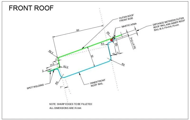
MASTER SECTION OF FRONT ROOF RAIL
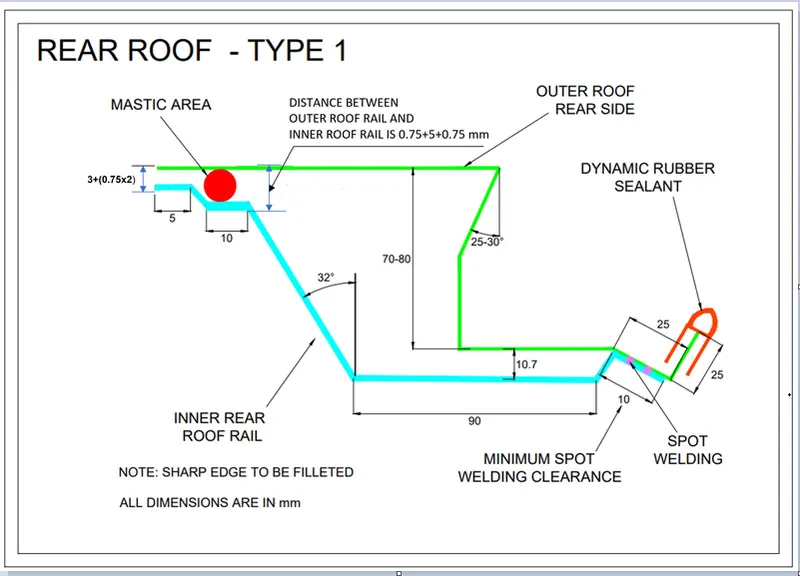
MASTER SECTION OF REAR ROOF RAIL
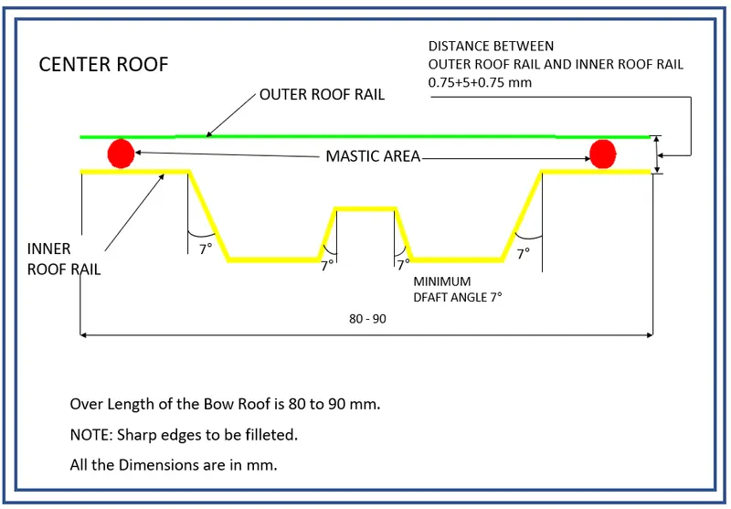
MASTER SECTION OF CENTER BOW ROOF
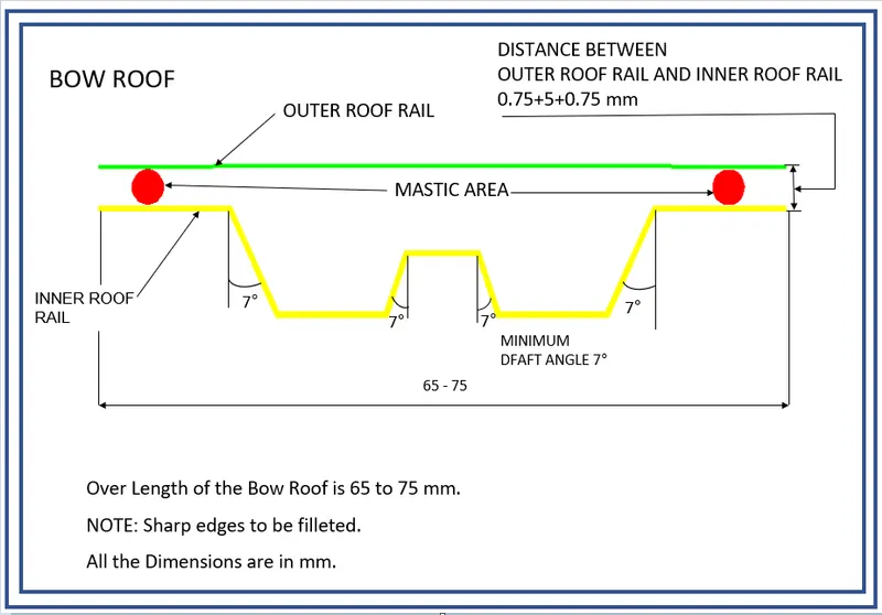
MASTER SECTION OF BOW ROOF
METHODOLOGY OF ROOF ASSEMBLY
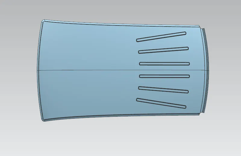
ROOF OUTER PANEL- Roof outer panel is the external surface or styling surface of the vehicle.
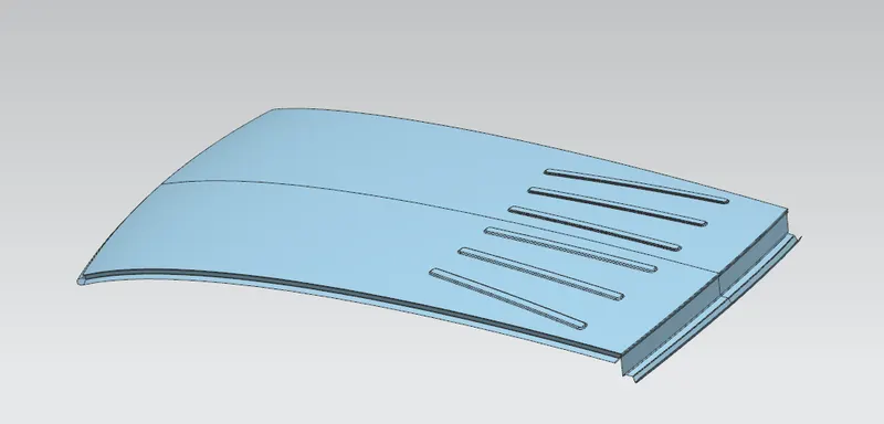
FRONT ROOF RAIL- Front roof rail is used to provide strength to the roof panel front and it also acts as link between windshield glass, roof panel and headliner (interior trim).
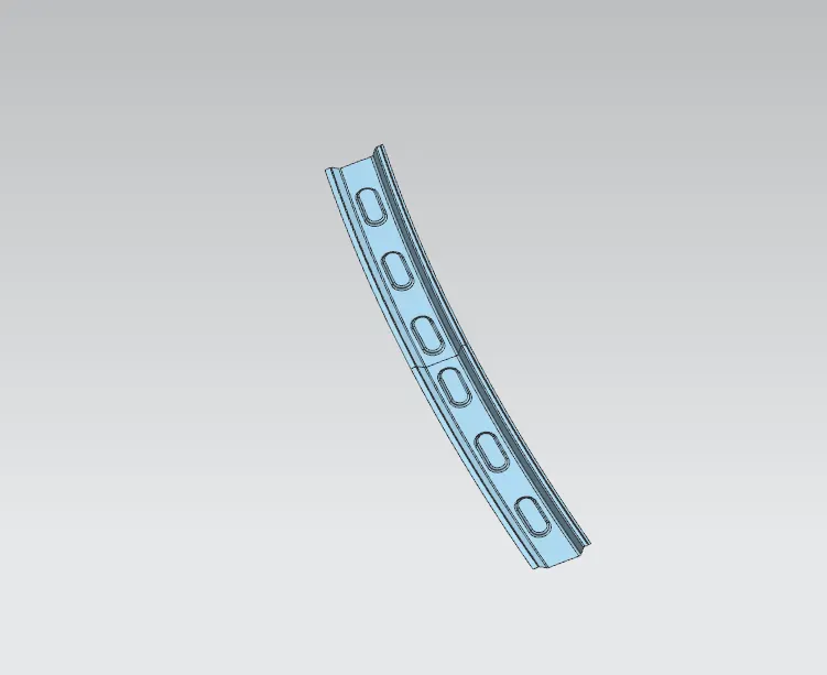
REAR ROOF RAIL- Rear roof rail provide the reinforcement similar like front roof rail. The design consideration is visibility criteria & passenger’s head room clearance. It is also important to give the design so that the trajectory of rear boot door can functionally operate smoothly.
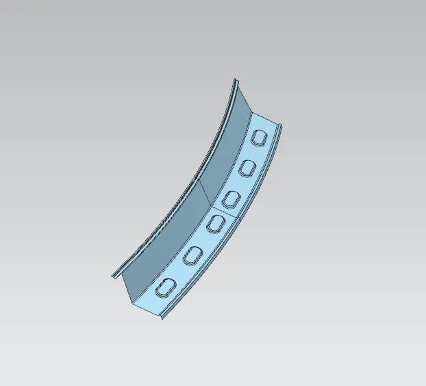
CENTRE BOW ROOF- Centre bow roof provide support to the flat area of the roof as it is susceptible to failure due to load. Mainly it is connected to the B-Pillar support structure. The centre bow roof helps to give strength during roll-over test.
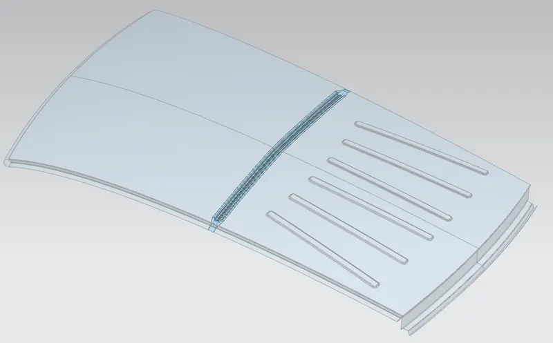
BOW ROOF- The bow roof is given to improve the torsional stiffness and load bearing capacity of the roof structure. The number of roofs presented is depends on the overall size of the roof. Presently in this project two bow roofs are calculated.
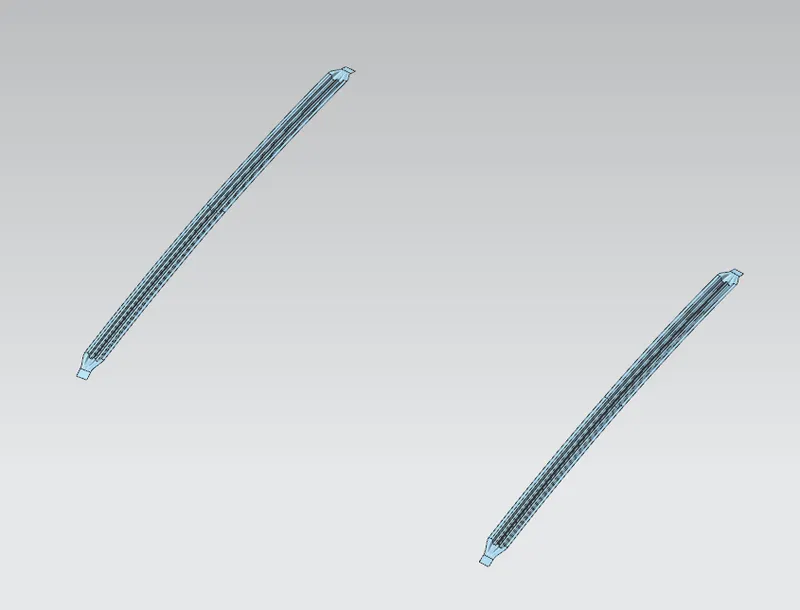
JOINING PROCESS-
The separate components which developed between the roof outer panels & reinforcements are joined by mastics & spot weld. Mastics are introduced for remarkable strength. Spot weld is also introduced to join the reinforcement & the outer panel.
DESIGN CALCULATION OF ROOF
To pass the design consideration of roof, there are analysis test & criteria which is need to consider it. They are;
- Heat Distortion Method
- Snow Load Method
HEAT DISTORTION METHOD
Heat Distortion is the temperature at which the metal softens and deforms under a specific load. This study is done to check the ability of the roof to withstand high temperature with respect to the positioning of the reinforcements which contributes to increase the strength.
Bow–Roof Prediction Formula
W = [1.73 x 10^ (-3) x L] + [1.85 x 10^ (-8) x (R^2)/t] + [ 1.10x10^ (-3) x l] - 2.68
Where,
L = Roof Length in X-Direction[mm](Roof dimension in 0-Y)
R = Roof curvature
R = 2(Rx*Ry)/(Rx+Ry)
Rx = X curvature
Ry = Y curvature
t = Roof plate thickness [mm]
l = Bow Roof Span [mm]
Judgment Condition
OK< 2.7
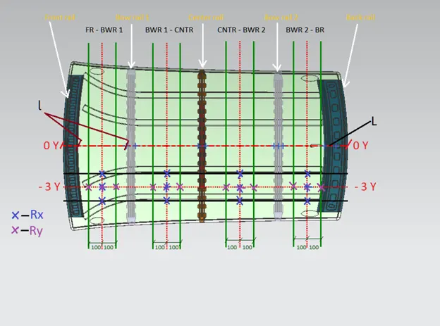
To find out Rx & Ry values
- Create a sketch on the top roof & draw a horizontal line at a centre (0 – Y).
- Offset this line to 300mm & called it -3Y line.
- From -3Y line, offset 100mm either way in both directions. This is to done to find Rx & Ry points.
- Mark the intersecting point & projected it on the outer panel of the roof.
- Mark it through 3-arc centre in Rx & Ry direction on the outer panel of the roof.
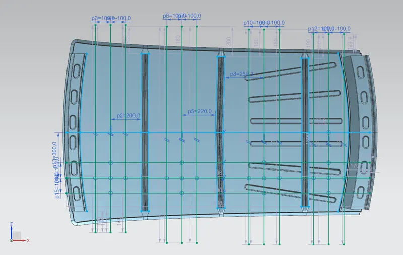
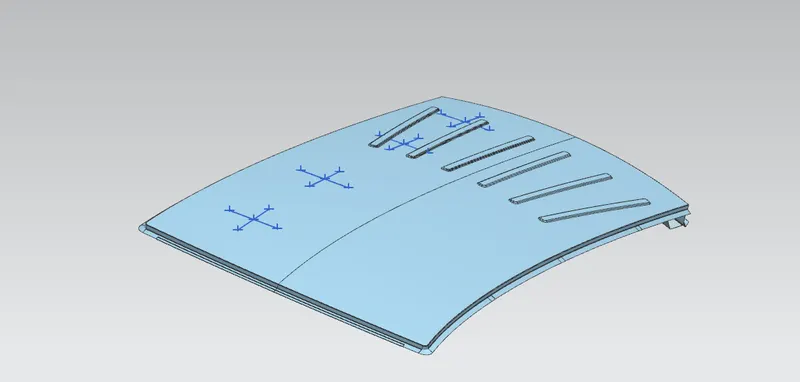
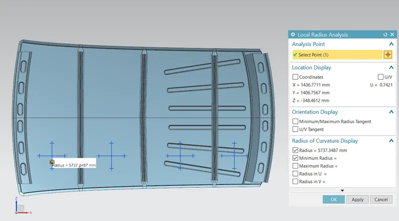
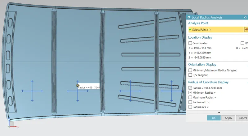
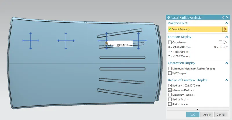
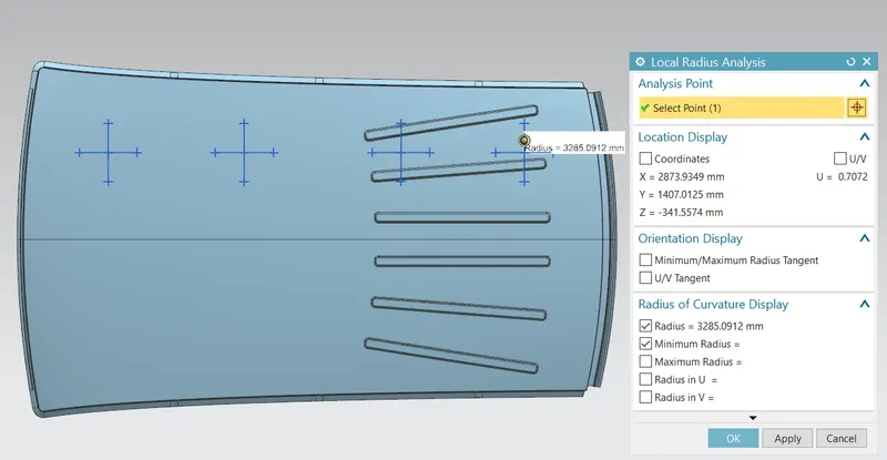
Radius of Rx value for Heat Distortion
Radius of Ry value for Heat Distortion
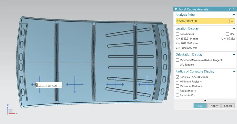
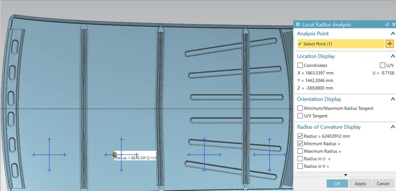
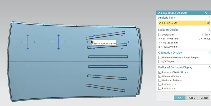
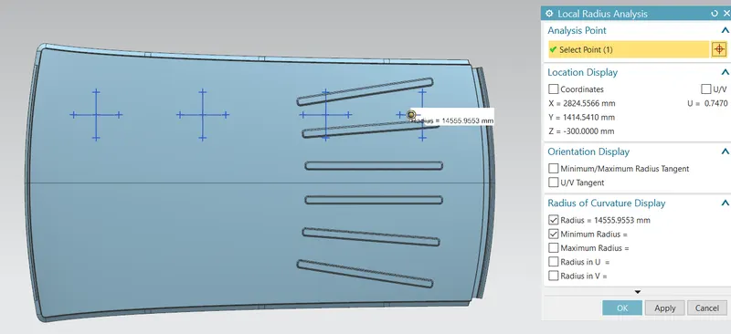
CALCULATION OF HEAT DISTORTION
|
SL NO |
BOW ROOF |
Rx |
Ry |
R |
t |
l |
L |
W |
RESULT |
|
1 |
F.R to Bow 1 |
5737.348 |
2577.082 |
3556.615 |
0.75 |
400.17 |
1999.417 |
1.53 |
O. K |
|
2 |
Bow 1 to centre |
4961.704 |
6240.091 |
5527.950 |
0.75 |
440.017 |
1999.417 |
2.01 |
O. K |
|
3 |
Centre to bow 2 |
3922.427 |
10863.821 |
5763.807 |
0.75 |
518.460 |
1999.417 |
2.61 |
O. K |
|
4 |
Bow to R. R |
3285.091 |
14555.955 |
5360.407 |
0.75 |
257.451 |
1999.417 |
1.76 |
O. K |
From the above table it can be concluded that all values of W < 2.7 and also not W > 3.1. So thus, infers that current positioning of bow row are good in state as per design and found ok.
SNOW LOAD METHOD
Snow load is the downward force on a building's roof by the weight of accumulated snow and ice. The roof or the entire structure can fail if the snow load exceeds the weight the building was designed to shoulder. Or if the building was poorly designed or constructed.
Snow Load Prediction Formula
Qr = [Iy x t2] / [α x s x [(Rx + Ry)/2]2 x 10-8]
Note: The Qr value given over here is correct. There was a typo error in the formula given in the video.
Where,
α = My x Lx2 x 10-12 , My = Y(Ly-Y)
t = Roof plate thickness [mm]
Ly = Distance between the front and rear roof Rails on the Vehicle along with 0Y[mm]
Length of Roof panel with the centre point between Roof rail Front /Rear as the front and rear reference point.
Lx = Distance between the Left and Right end of the roof on the Roof BOW [mm]
The width of the roof panel is exposed on the surface.
Y = Distance front Roof Rail to Roof BOW [mm]
s = Distance for which Roof BOW bears divided load [mm]
s = L1/2 + L2/2
Iy = Geometrical moment of inertia of Roof BOW (Y cross-section) [mm4]
Rx = Lateral direction curvature radius of roof panel Y cross-section on Roof BOW [mm]
Roof panel curvature Radius of the Length Lx in Front view
Ry = Longitudinal Direction curvature radius of the Roof panel X cross-section on Roof BOW [mm]
Roof panel X curvature radius of length s in Side view
Judgment condition
Qr ≥ 3.1
250 ≤ s ≤ 380
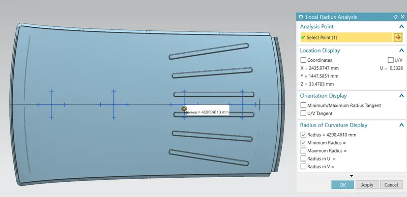
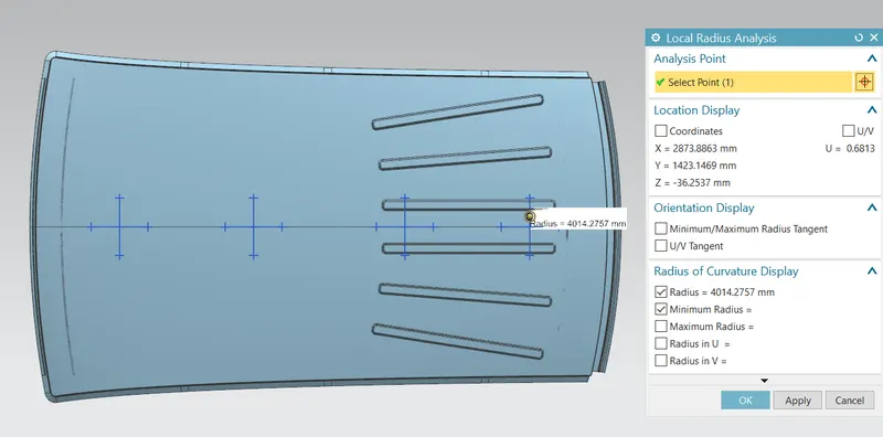
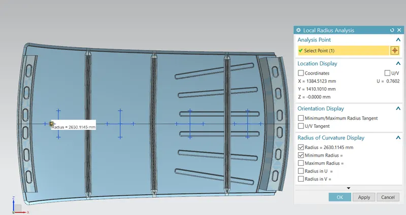
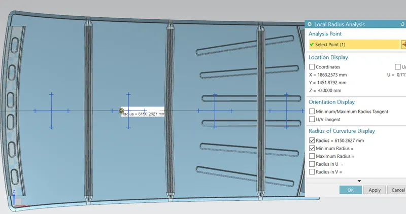
To find out Rx & Ry values
- Create a sketch on the top roof & draw a horizontal line at a centre (0 – Y).
- From (0-Y) line, offset 100mm either way in both directions. This is to done to find Rx & Ry points.
- Mark the intersecting point & projected it on the outer panel of the roof.
- Mark it through 3-arc centre in Rx & Ry direction on the outer panel of the roof.
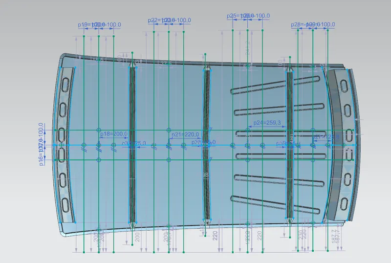
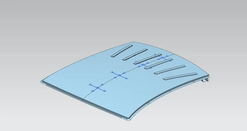
Radius of Rx value for Snow load
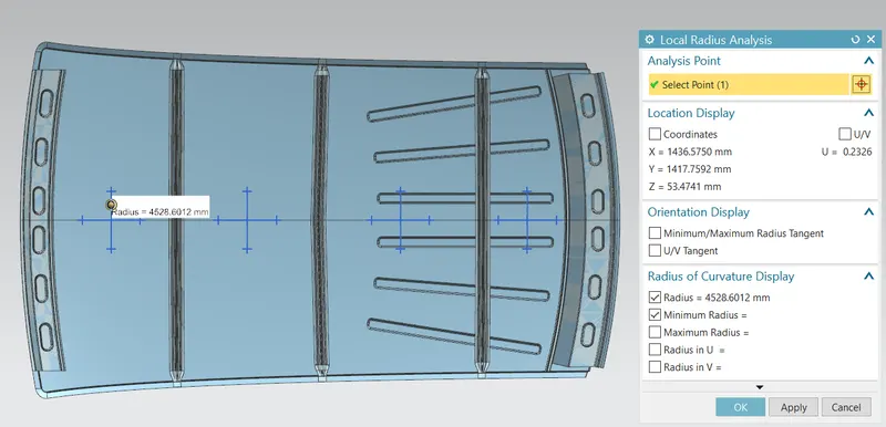
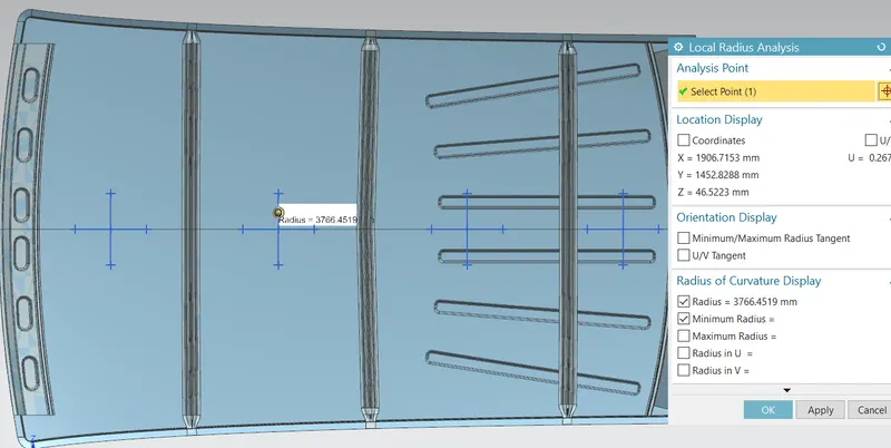
Radius of Ry value for Snow load
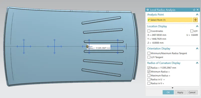
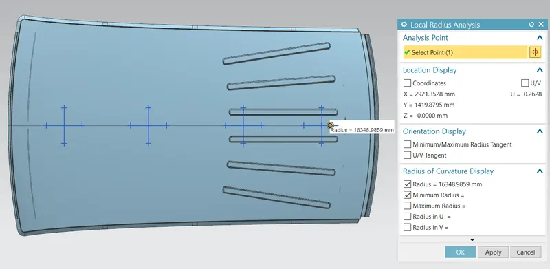
CALCULATION OF SNOW LOAD
|
SL NO |
BOW ROOF |
Rx |
Ry |
Lx |
Ly |
Y |
Iy |
S |
α |
t |
Qr |
Result |
|
1 |
FR RF & BOW 1 |
4528.601 |
2630.114 |
1136.994 |
1999.417 |
475.827 |
1.507*10^3 |
482.915 |
0.9371 |
0.75 |
14.62 |
O. K |
|
2 |
BOW 1 & CTR BOW |
3766.451 |
6150.262 |
1086.605 |
1999.417 |
965.831 |
0.1653*10^3 |
529.234 |
1.178 |
0.75 |
0.60 |
N. G |
|
3 |
CTR BOW & BOW 2 |
4290.461 |
11295.296 |
1057.517 |
1999.417 |
1534.296 |
1.515*10^3 |
465.043 |
0.7980 |
0.75 |
3.78 |
O. K |
It is observed in the tabular calculation that Bow 1 & CTR Bow roof snow load is not satisfying. To optimize the snow load, increase the width of the bow roof or embossing on the outer panel to counter the snow load on the roof surface can withstand it.
SECTION MODULUS
It is the ratio of Moment of Inertia (I) of the beam cross-section about the neutral axis to the distance (ymax) of extreme fibre from the neutral axis.
Section Modulus, S = I/y
where I = Moment of Inertia (mm4).
Y = distance between the neutral axis and the extreme end of the object (mm).
SECTION MODULUS CALCULATION FOR BOW ROOF 1
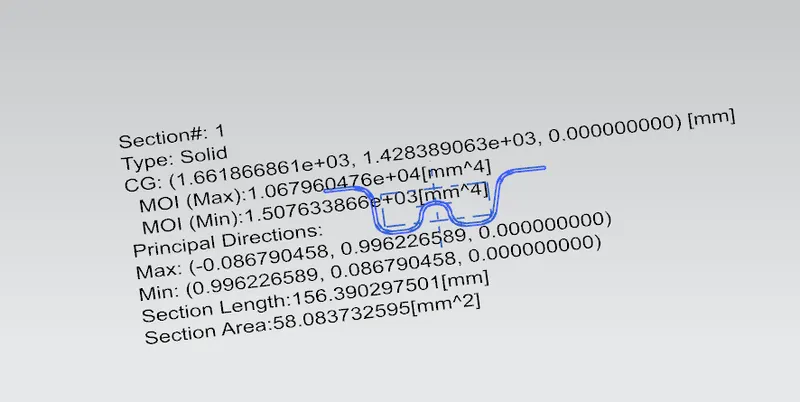
Moment of the inertia maximum, (MAX) I max =10679.60 mm4
Moment of the inertia minimum, (MIN) I min =1507.63 mm4
Section modulus (S) = Moment of inertia/ distance from neutral axis to any given fibre
S = I/Y
I = 1507.63mm4
Y = 50.06 mm/2 = 25.03mm
S = 60.23 mm3
SECTION MODULUS CALCULATION FOR CENTER BOW ROOF
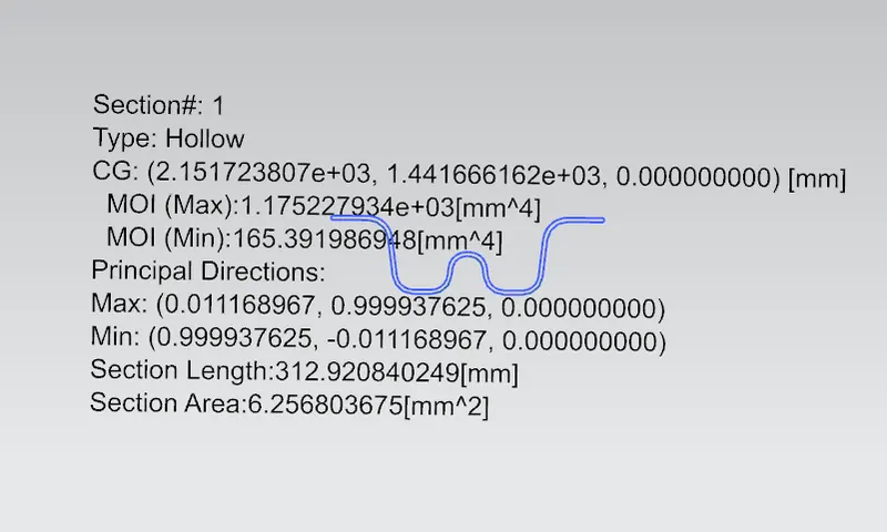
Moment of the inertia maximum, (MAX) I max =117.52 mm4
Moment of the inertia minimum, (MIN) I min = 165.39 mm4
Section modulus (S) = Moment of inertia/ distance from neutral axis to any given fibre
S = I/Y
I =165.39 mm4
Y = 50.05 mm/2 = 25.025mm
S = 6.60 mm3
SECTION MODULUS CALCULATION FOR BOW ROOF 2
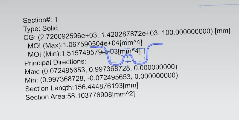
Moment of the inertia maximum, (MAX) I max =10675.90 mm4
Moment of the inertia minimum, (MIN) I min = 1515.74 mm4
Section modulus (S) = Moment of inertia/ distance from neutral axis to any given fibre
S = I/Y
I = 1515.74 mm4
Y = 50.05 mm/2 = 25.025mm
S = 60.56 mm3
DRAFT ANALYSIS
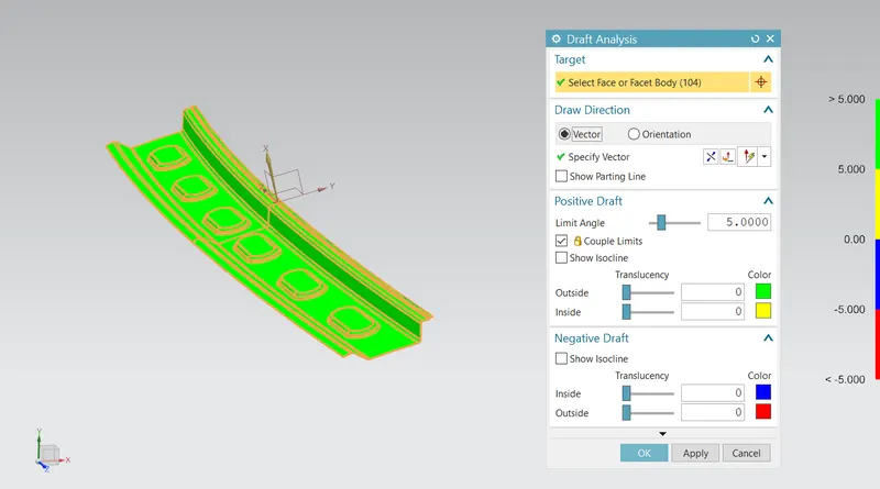
The Draft Analysis allows the user to easily analyse a part for proper draft angle. A Draft Angle describes the amount of taper for moulded or cast parts perpendicular to the parting line.
This type of analysis is performed on colour ranges to identifying zones on the analysed element where the deviation from the draft direction at any point, corresponds to specified values.
Minimum draft angle of 7 degree is considered for analysis, green colour infers on the parts that all face along the tooling direction has positive draft angle greater than 5 degree and passed in analysis.
FRONT ROOF RAIL
BOW ROOF 1
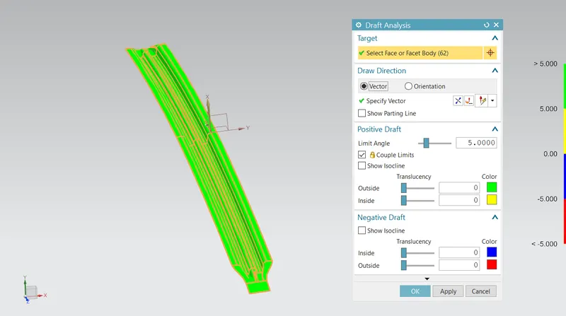
CENTER BOW ROOF
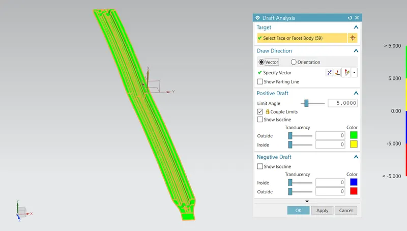
BOW ROOF 2
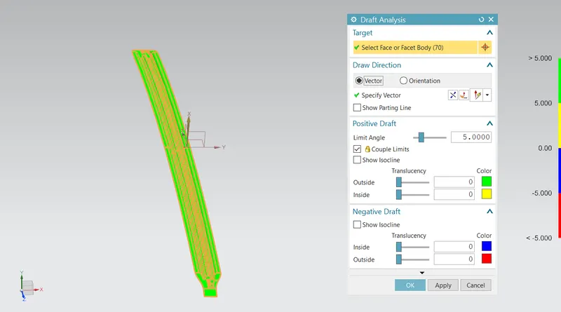
REAR ROOF RAIL
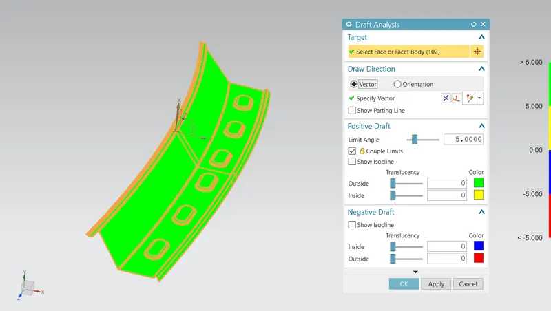
ROOF
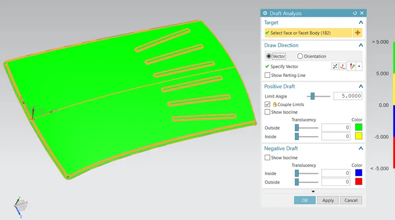
CONCLUSION-
Thus, the required reinforcement & the ditch area for the roof were designed & developed from the given styling. The curvature study was done after performing calculation for Heat distortion & Snow load condition has been done.
Further the section modulus study was conducted 7 draft analysis were done for each reinforcement successfully.