Roof Design
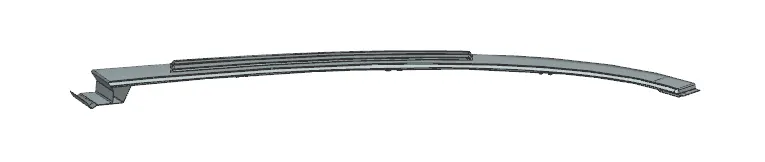
Aim:- For the Given Roof styling, create an ASSEMBLY by developing the essential flanges for the outer roof and creating the reinforcements
Theory:-
An automobile roof or car top is the portion of an automobile that sits above the passenger compartment, protecting the vehicle occupants from sun, wind, rain, and other external elements. It is design to withstand the external forces & impacts and safe gaurd the passengers.
Components of the Roof:-
- Front Roof Rail
- Bow Roofs
- Center Roof rail
- Rear Roof Rail
DESIGN CONSIDERATIONS FOR A ROOF:-
- Visibility criteria
- Head clearance
- Curvature study
- Snow load criteria
- Draft analysis
Manufacturing Techniques:-
- Stamping Process:- The process of turning sheets of metal into a useful part or component is called sheet metal stamping. The metal is fed into a press, where the stamping tool, also known as a die, creates the desired shape
- Joining Technique
- Spot welding:- Spot welding (or resistance spot welding) is a type of electric resistance welding used to weld various sheet metal products, through a process in which contacting metal surface points are joined by the heat obtained from resistance to electric current.
- Mastic Glue:- Mastic Glue is used to stick two metal surfaces, by using mastic glue we can avoid the weld marks & used to reduce the NVH between the two surfaces. One mastic glue can influence the radius of 40~80mm(Mastic Influence).
Calculation:-
Bow–Roof Prediction:-
W = [1.73 x 10^(-3) x L] + [1.85 x 10^(-8) x (R^2)/t] + [ 1.10x10^(-3) x l] - 2.68
Where,
L = Roof Length in X-Direction[mm](Roof dimension in 0-Y)
R = Roof curvature
R = 2(Rx*Ry)/(Rx+Ry)
Rx = X curvature
Ry = Y curvature
t = Roof plate thickness [mm]
l = Bow Roof Span [mm]
Judgment Condition
OK If W<2.7 Or 2.7>W>3.4
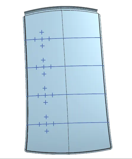
| Heat Distortion Criteria | ||||||||
| S.No | L | Rx | Ry | R | t | l | W | Result |
| Fr & 1st | 2022 | 5622.6788 | 3400.2649 | 4237.7738 | 0.7500 | 1117.2819 | 2.490052 | OK |
| 1st & Ctr | 2022 | 4858.3192 | 6662.1241 | 5619.0069 | 0.7500 | 1081.6660 | 2.786699 | OK |
| Ctr & 2nd | 2022 | 4070.1676 | 9476.5189 | 5694.5320 | 0.7500 | 1056.9873 | 2.780629 | OK |
| 2nd & Rr | 2022 | 3431.1354 | 12340.4526 | 5369.3723 | 0.7500 | 1046.8945 | 2.680788 | OK |
Snow Load Prediction Formula
Qr = [Iy x t2] / [α x s x [(Rx + Ry)/2]2 x 10-8]
Note: The Qr value given over here is correct. There was a typo error in the formula given in the video.
Where,
α = My x Lx2 x 10-12 , My = Y(Ly-Y)
t = Roof plate thickness [mm]
Ly = Distance between the front and rear roof Rails on the Vehicle along with 0Y[mm]
Length of Roof panel with the center point between Roof rail Front /Rear as the front and rear reference point.
Lx = Distance between the Left and Right end of the roof on the Roof BOW [mm]
The width of the roof panel is exposed on the surface.
Y = Distance front Front Roof Rail to Roof BOW[mm]
s = Distance for which Roof BOW bears divided load [mm]
s = L1/2 + L2/2
Iy = Geometrical moment of inertia of Roof BOW (Y cross-section )[mm4]
Rx = Lateral direction curvature radius of roof panel Y cross-section on Roof BOW [mm]
Roof panel curvature Radius of the Length Lx in Front view
Ry = Longitudinal Direction curvature radius of the Roof panel X cross-section on Roof BOW [mm]
Roof panel X curvature radius of length s in Side view
Judgment condition
Qr ≥ 3.1
250 ≤ s ≤ 380
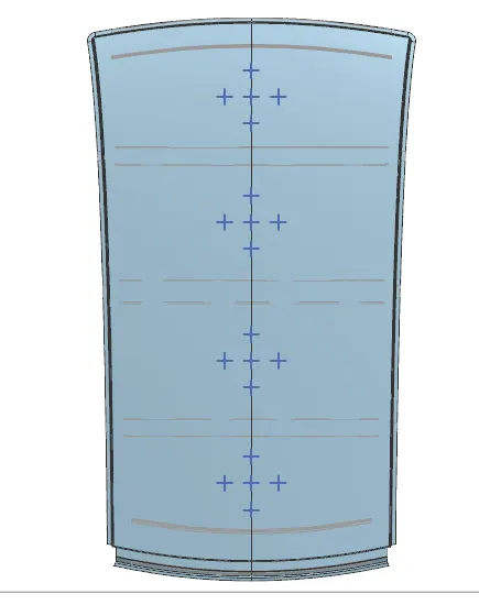
| Snow Load Calculation | ||||||||||||||
| S.No | Rx | Ry | Lx | Ly | Y | My | L1 | L2 | s | α | Iy | t | Qr | Result |
| Fr & 1st | 4572.135 | 2559.005 | 1135.3948 | 2022.226 | 470.75 | 730357.4 | 470.75 | 510.62 | 490.685 | 0.941519 | 721.83 | 0.75 | 6.913014 | OK |
| 1st & Ctr | 3739.539 | 6063.405 | 1083.7325 | 2022.226 | 981.37 | 1021465 | 510.62 | 511.09 | 510.855 | 1.199686 | 928.45 | 0.75 | 3.547012 | OK |
| Ctr & 2nd | 4276.174 | 11094.53 | 1054.6716 | 2022.226 | 1492.46 | 790654.9 | 511.09 | 478.34 | 494.715 | 0.879471 | 726.8 | 0.75 | 1.590864 | NG |
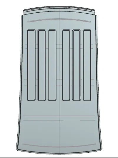
Result :- The roof has failed the snow load test, so we have used emboss to improved the strength of the roof.
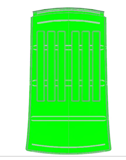
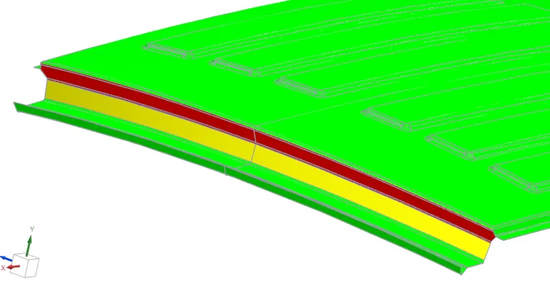
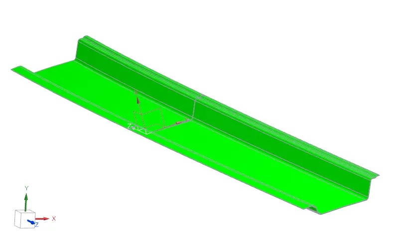
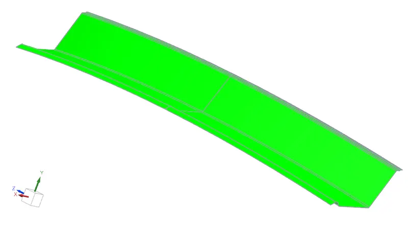
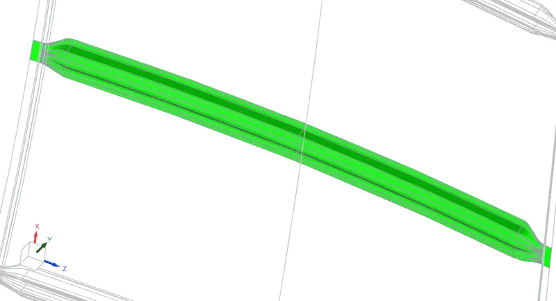
Draft Analysis:- Minimum draft angle is 7 degree is considered for analysis. Green colour show positive draft angle of the part more than 7 degree.The draft analysis is done on the roof parts and the results are as follows:-
In Top roof we have 2 flanges with draft angle between 0~5 i.e. positive draft and 1 flange with negative draft, that surface can be cleared with another direction of the draft analysis.
All the other component have cleared the draft analysis with minimum of 7 Degree of clearance.
Top Roof:-
Front Roof Rail:-
Rear Roof Rail:-
Center Roof Rail:-
1st Bow Roof Rail:-
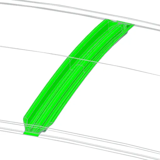
2nd Bow Roof Rail:-
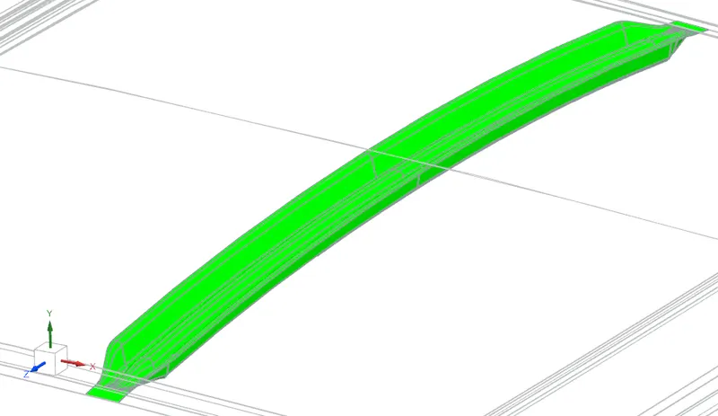
Top View:-
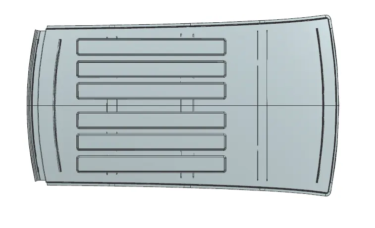
Back View:-
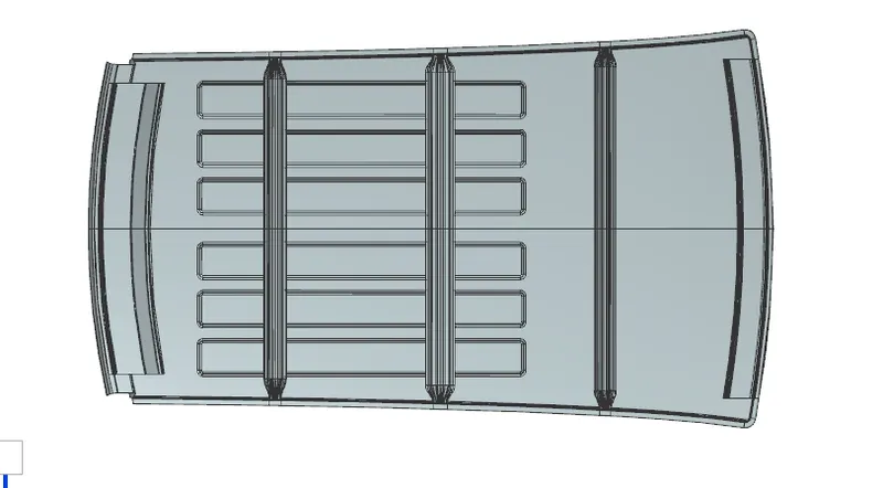
Side View:-
Isomertric View:-
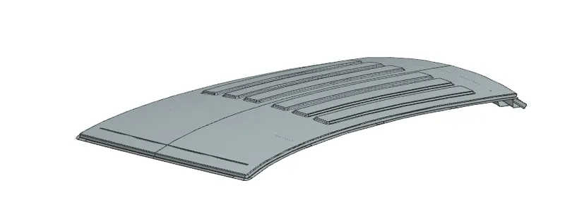
Conclusion :-The roof design has been done with considering all the design parameters successfully.