Roof Design
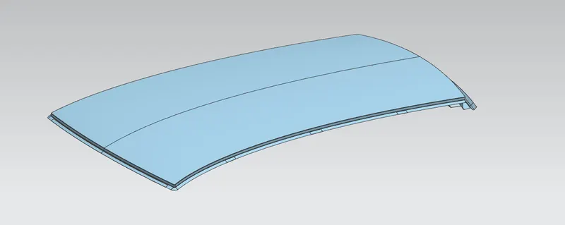
ROOF DESIGN
by
Santhosh sivan.G
Introduction
It is the design of BIW (Body in White) of an automotive roof. Front roof rail is one of the important parts in roof for proper strength and rigidity. Front roof rail give mounting features like bracket map lamp and room lamp. Proper care has been taken to provide space for welding and part joining. For additional strength, embosses are been provided. Rear roof rail is similar to the front roof rail. Rear headroom and rear visibility criteria are considered and also tailgate will be mounted on the rear roof rail so tailgate conditions have to be considered while designing the rear roof rail. Bow roof has been provided for additional strength especially against snowing condition and rollover situation. In this model, one bow roof has been provided between rear roof rail and center roof rail. Centre roof rail along with reinforcement is attached to the roof by a spot welding method. No embosses has been provided. It can be added as per required strength of the car. Another one bow roof has been placed between the center roof rail and rear roof rail. Ditch area has been provided on all the four sides of the roof. Roof ditch areas are provided to mount roof to the main body of the car also to mount windshield glass for the front ditch area, and to mount tailgate to rear ditch area.
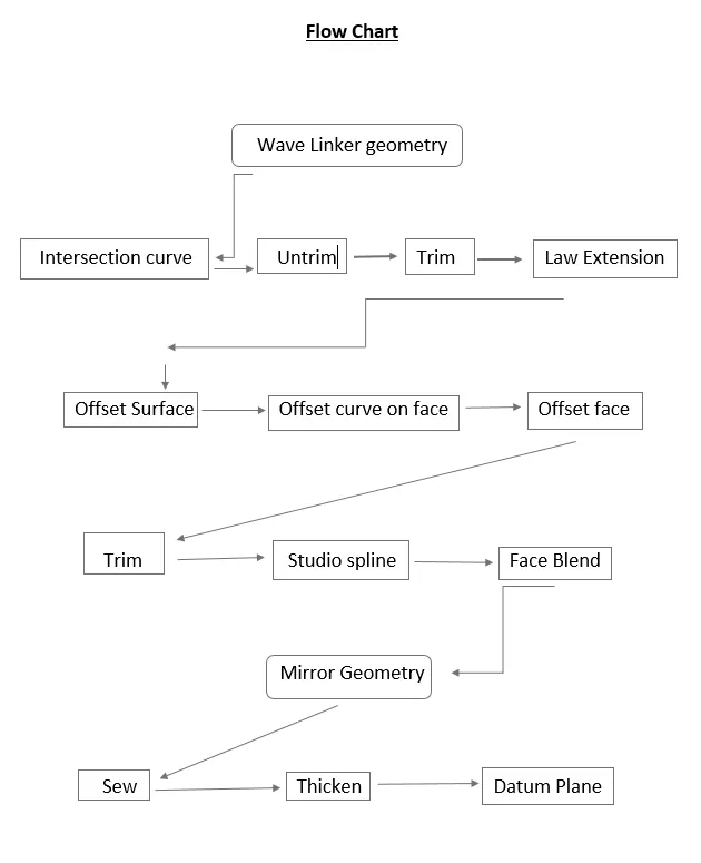
Law Extension, through curve, Intersection curve, project curve, trim sheet, offset face on surface and etc. Those commands are used to create roof and most important thing for creating center, front, bow and rear roof rails in roof the all components should come under single assembly file.
Now we can see how to create and analysis the roof by step by step with the help of flow chart
Master section:
Master section means guides for design requirements which shapes the component after technical styling of class A surface. Here they are three types of master section there for creating bow roof, center roof and rear roof rail. In master section clearly mention all design parameters and tolerances.
Front roof rail:
Master section for Front roof Rail:
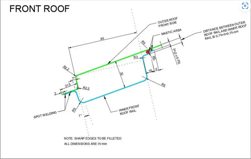
With help of this we can create our front roof rail then make the draft analysis. The purpose of front roof to mounting a wind sheld, wipers and some other components. Not only that it can protect the person from mositer content while driving.
Front roof design:
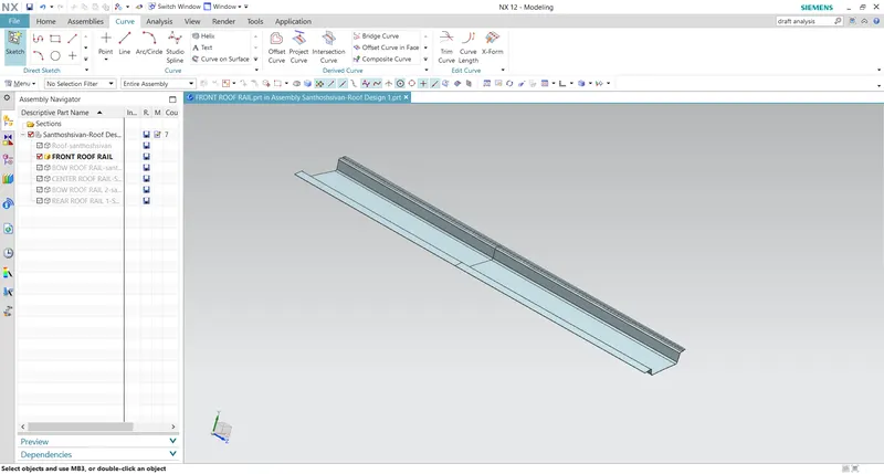
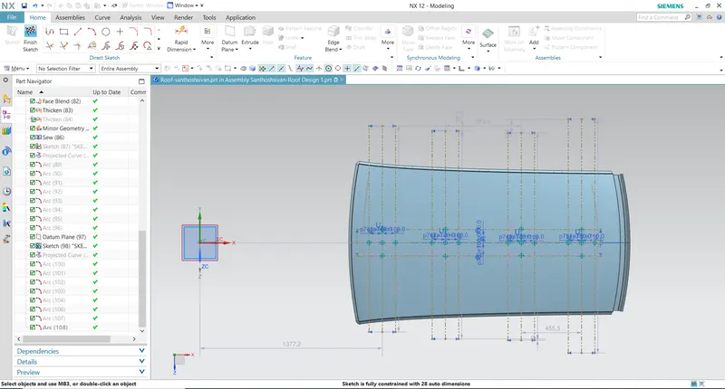
For front roof rail with the help of Wave geomentry link, law extension, face blend, offsect curve and trim as created front roof.
Draft analysis:
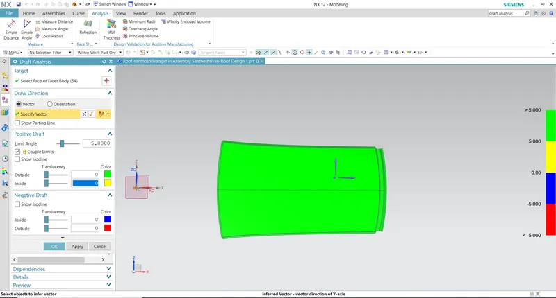
Draft analysis is nothing but to analysis the draft angle of our component.
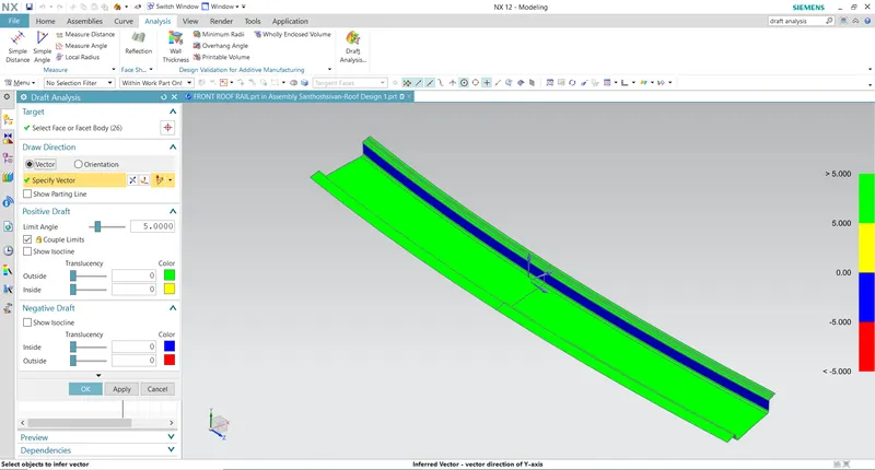
In draft analysis the colour variation show the draft deviations (positive or negative).
Rear Roof Rail:
Master section for rear roof rail:
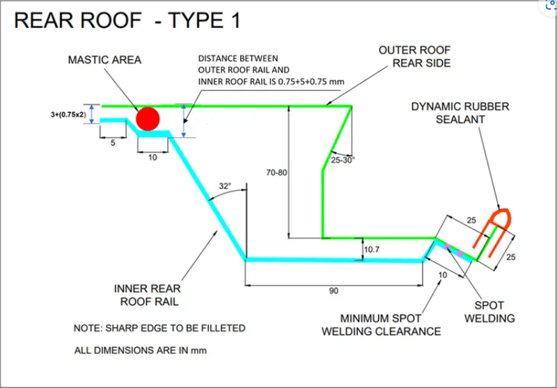
The above is the master section for our rear roof rail, with the help of this we can create our rear roof rail in PLM NX 12. Purpose of rear roof is to mount the back door for luggage purpose. It was designed by taking the rear door clearence. The taken clearence will not affect back door opening and closing on the roof.
With the help of spot weld we can joint our hinge on the back door. Aslo for increasing the roof strength emboss has to be created.
Rear roof desing:
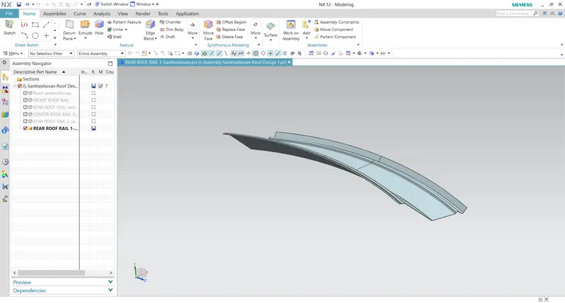
Same process we can use to create our rear roof design (Law extension, studi curve, trim offset surface and some other commands are used)
Draft analysis:
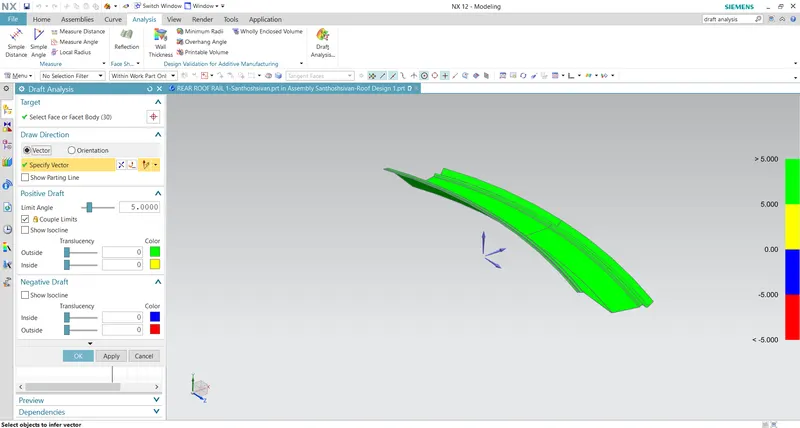
In draft analysis the colour variation show the draft deviations (positive or negative)
Bow roof rail (1 & 2):
Master section for Bow roof rail:
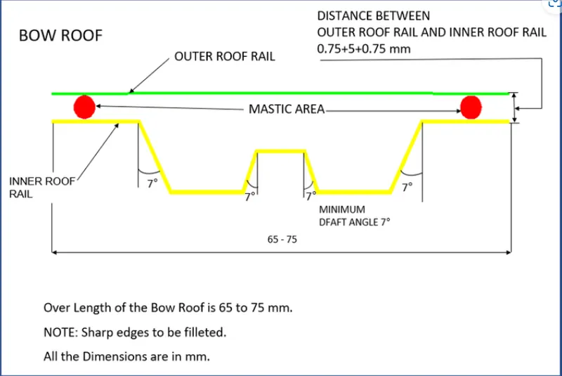
Bow roof rails were placed between the front and rear roof rails.Bow roof rails were added to increase the stiffness of the roof since it has the large flat surface. To increase the curvature result of the roof where it needs to withstand the heat distortion cirteria and snow load criteria the bow roofs were positioned as per the standards.The bow roofs were provided with mastic points since the joining process will be done using the mastic sealants.Spot welds also possible but it will damage the appearance of the car roof..The bow roof position needs to satisfy the head room clearance and draft analysis for Deep Drawing.
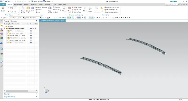
Bow roof design:
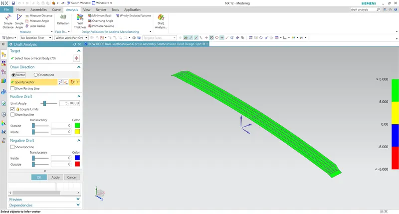
Draft analysis for Bow roof 1:
Draft analysis for Bow roof 2:
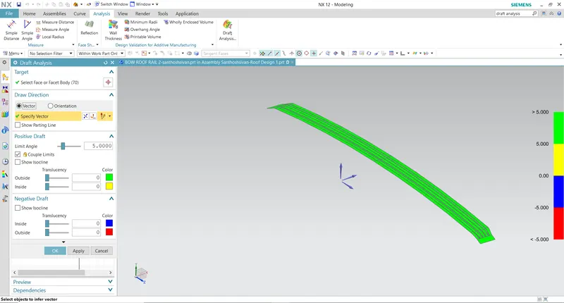
Both draft analysis shows the positivr and negative draft devation
Center roof rail:
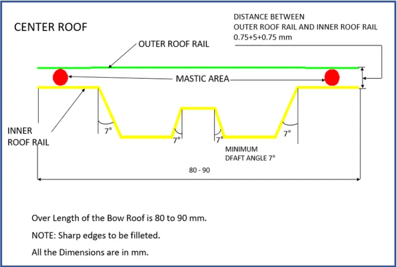
Center roof rail was place after the Bow Roof 1 in my model but it can also be swapped between the Bow Roofs but it should be positioned as center of the roof as much as possible. center roof rail was designed to have a reinforcement roof rail which helps the roof of a car to increase the efficiency.
Master section for Center roof rail:
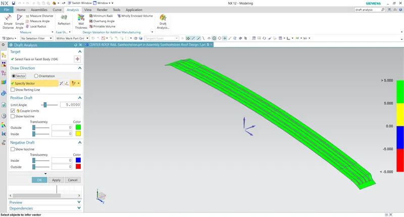
Both draft analysis shows the positivr and negative draft devation
Center roof rail:
Center roof rail was place after the Bow Roof 1 in my model but it can also be swapped between the Bow Roofs but it should be positioned as center of the roof as much as possible. center roof rail was designed to have a reinforcement roof rail which helps the roof of a car to increase the efficiency.
Master section for Center roof rail:
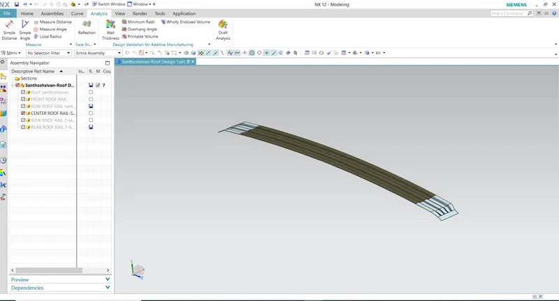
Center roof rail design:
Draft Analysis:
Heat Distortion Criteria:
Heat Distortion is the temperature at which the metal softens and deforms under a specific load. This study is done to check the ability of the roof to withstand high temperature.
Formula,
W = [1.73 x 10^(-3) x L] + [1.85 x 10^(-8) x (R^2)/t] + [1.10x10^(-3) x l] - 2.68
Judge mental Condition: OK< 2.7 > 3.1
Where,
L = Roof Length in X-Direction[mm](Roof dimension in 0-Y)
R = Roof curvature Rx = X curvature
R = 2(Rx*Ry)/(Rx+Ry) Ry = Y curvature
t = Roof plate thickness [mm]
l = Bow Roof Span [mm]
Table:

In this above table show the heat distortion on roof when the roof is in high temperature
Snow Load Criteria:
Snow Load Criteria to check the withstand ability of the roof when the snow loads over the roof during winter in snow fall regions. This study will also analyze the roof that whether the permanent deformation occurs or not after removing the snow load.
Formula,
Qr = [Iy x t^2] / [α x s x [(Rx + Ry)/2]^2 x 10^(-8)]
s = L1/2 + L2/2
α = My x Lx2 x 10-12 , My = Y(Ly-Y)
Where
Judgement condition = Qr ≥ 3.1, 250 ≤ s ≤ 380
t = Roof plate thickness [mm]
Ly = Distance between the front and rear roof Rails on the Vehicle along with 0Y [mm]
Lx = Distance between the Left and Right end of the roof on the Roof BOW [mm] i.e (Width of the roof panel exposed on the surface)
Y = Distance front Front Roof Rail to Roof BOW[mm]
s = Distance for which Roof BOW bears divided load [mm]
Iy = Geometrical moment of inertia of Roof BOW (Y cross-section )[mm4]
Rx = Lateral direction curvature radius of roof panel Y cross-section on Roof BOW [mm]
Roof panel curvature Radius of the Length Lx in Front view
Ry = Longitudinal Direction curvature radius of the Roof panel X cross-section on Roof BOW [mm]
Roof panel X curvature radius of length ‘s’ in Side view
Table:

In this above table show the snow load criteria on roof after the removing the snow load.
Roof Design:
Roof Design:
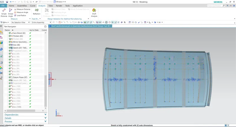
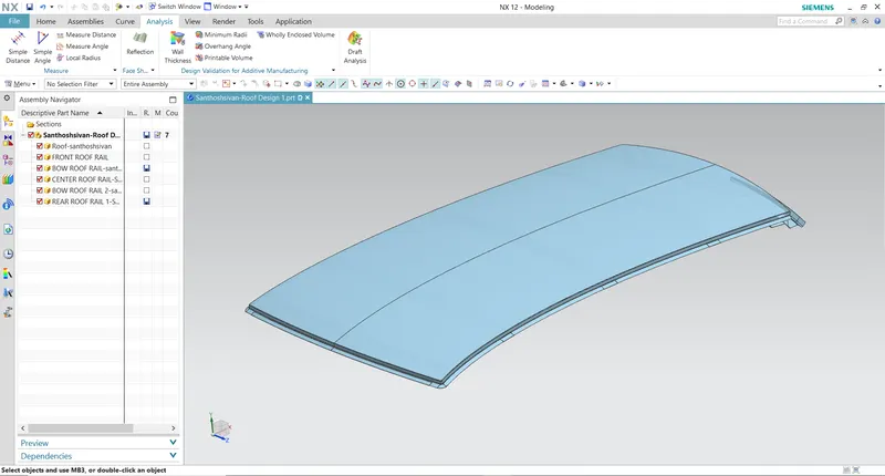
The outer surface designed by the styling team for the vehicle, the BIW team design the mountings on the vehicle by considering the necessary reinforcement to support the structure. The reinforcements are designed by considering the necessary load conditions.Designer also create the Ditch area in order increase more strength.First thing to consider while designing the roof is the opening angle, of the flanges such that there is no negative draft.If the roof rail is flat it is weak and if it is tilted or curved then it has more strength.As the roof is large so to increase the strength of the roof where it appears flat due to its long distance Roof Bow are given to increase the strength of the roof.Since the roof has numerous functions so the roof has to be stronger enough to withstand the damage experienced by it. To have good strength and stiffness, the Roof consists of components.
Roof design:
Draft Analyais:
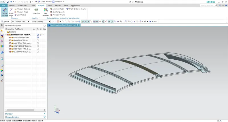
Roof Assembly:
Conclucsion:
Conclude that the Bow-roof the Daft analysis, Heat Distortion and Snow Load Criteria calculations were performed. Overall the BIW roof of a car was designed and achieved a better result.