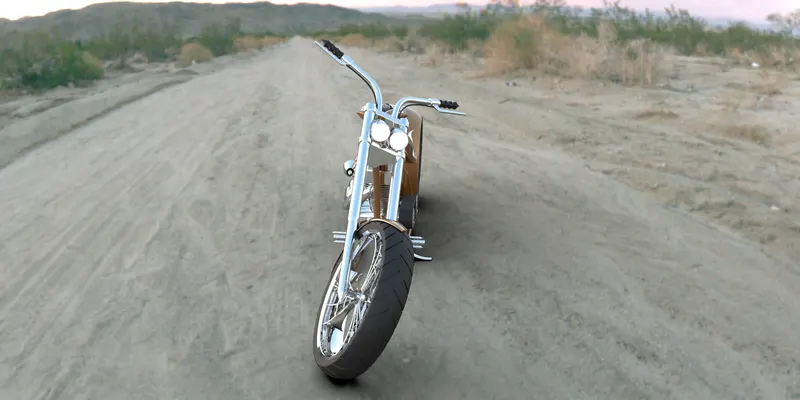
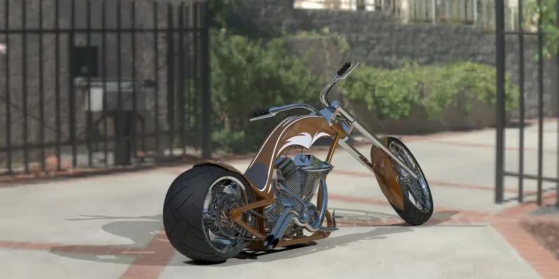
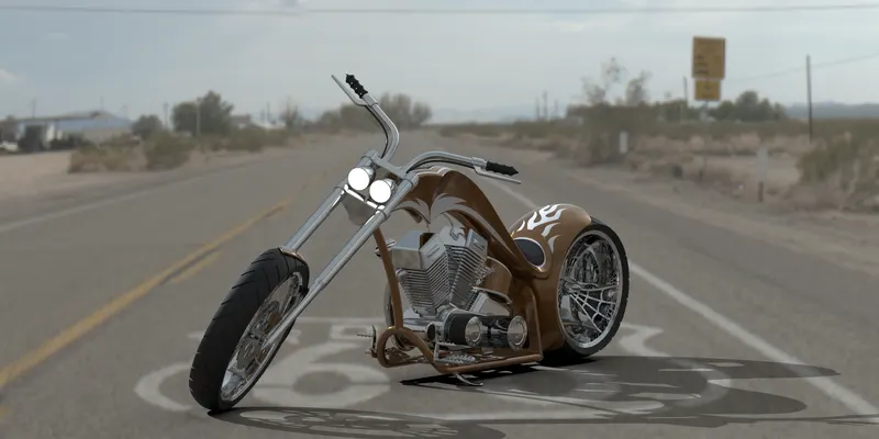
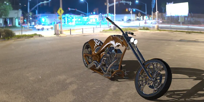
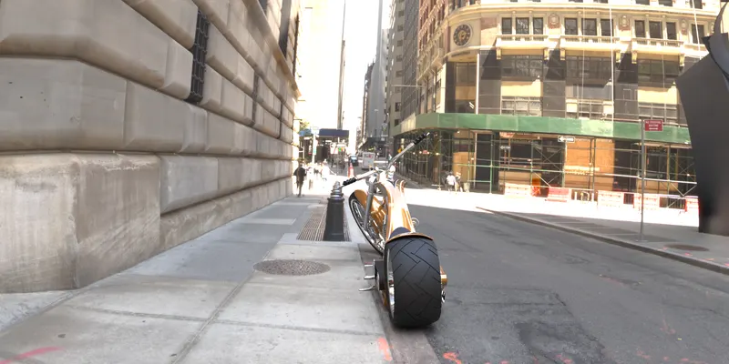
Photo Realistic Rendering
MODELING OF AMERICAN CHOPPER ON SOLIDWORKS
By
Santhoshsivan. G
INTRODUCTION
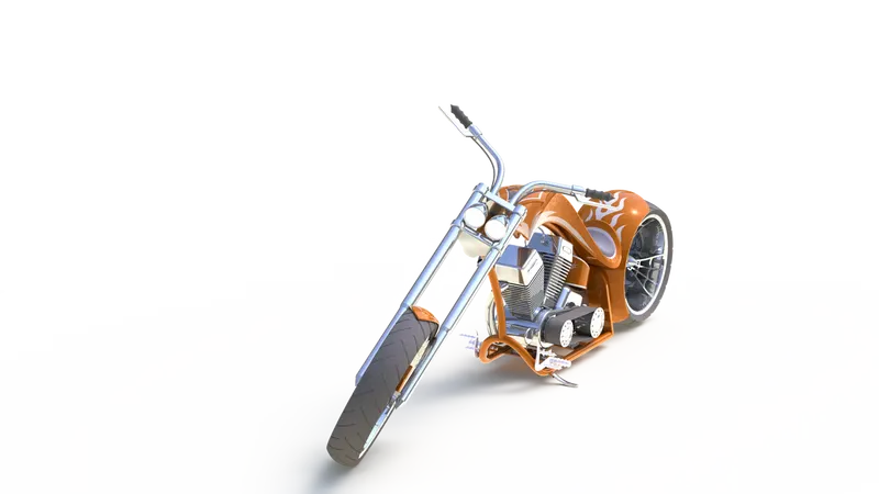
This project we learn the entire modeling of an American chopper in solidworks and also, we learn how to render the model (American chopper) in solidworks visualize.
The different types of components used for built the chopper are following below.
- Chassis
- Transmission belt
- Kickstand
- Chain
- Front and rear wheel with sprocket and brake caliper
- Front and rear fender
- Front fork along with handlebars and grip
- Engine with exhaust
- Gas tank
This are the components we model in solidworks software.
After finished the following component we look over the assemble and the rendering, in solidworks visualize. The main thing of rendering is to show the complete realistic view of the American chopper.
DESIGN APPROACH:
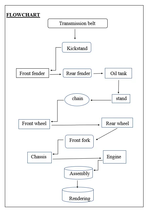
Starting with the transmission belt and till the rendering of chopper has been describe step by step of below flow chart.
FLOWCHART
Let us show what are the properties and features used to design a different part of our American chopper.
EXTRUDE BOSS:
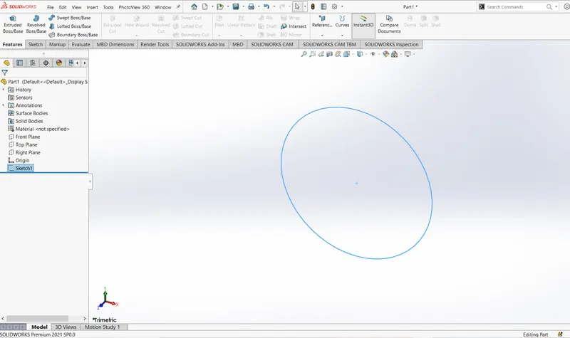
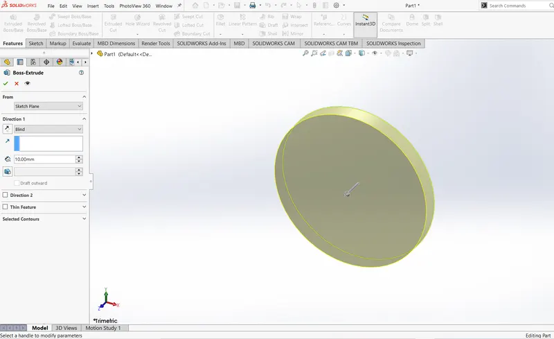
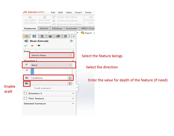
Extrude boss is the common feature use to add the material in solidworks. Before using extrude select the plane for your part to be create after, that draw the component (note: The entire component should fully define). Finishing the sketch exit and go to extrude in feature tab. Then click the extrude boss icon, the dialogue box appears. In that dialogue box select the sketch plane, in that tab shows offset, midpoint, etc select one if you need. Otherwise simply go to direction, select the sketch and enter the value then ok.
FILLET:
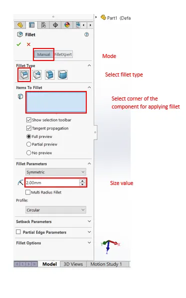
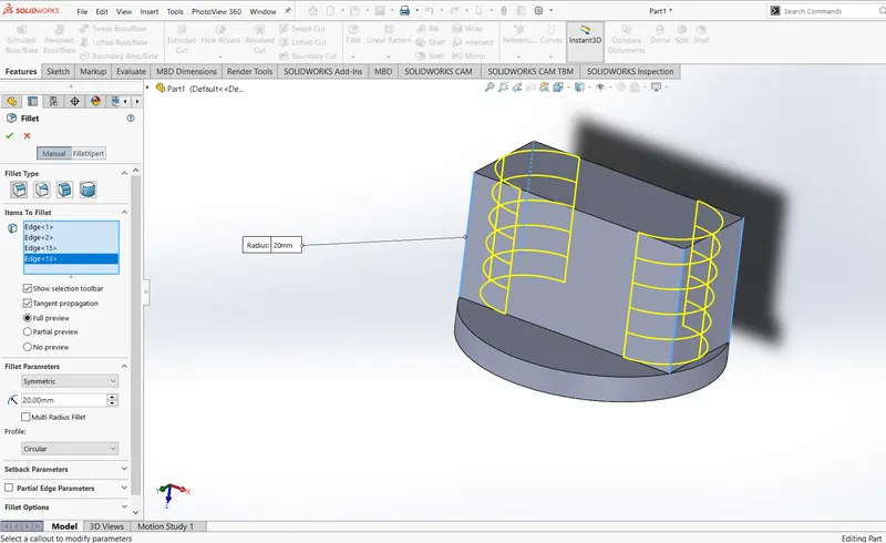
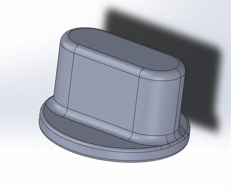
Fillets are main thing to design the component. The main use of fillets is to make the edge round off and removing the corner in the designed component. The material removed in the component depending upon the edges whether it’s in internal or in external. Noted that depending upon the different size of fillet created as to separate feature. By selecting fillet icon in feature tab, the fillet dialogue box appears. In that dialogue box select fillet type according to your component design and in fillet tab select the item to fillet option, then select the corners for applying fillet. Finally apply the value in fillet parameter option and click ok.
REVOLVED BOSS FEATURE:
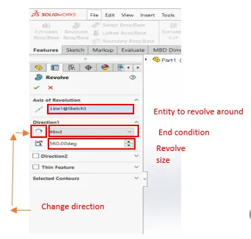
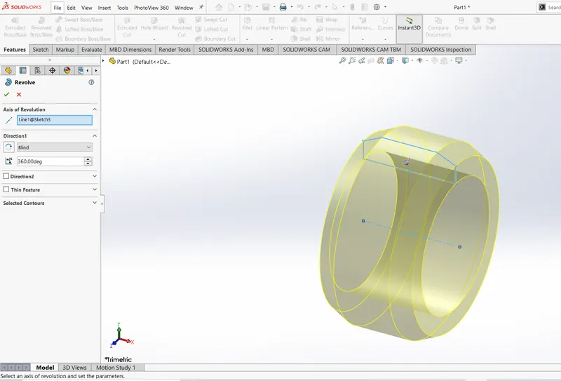
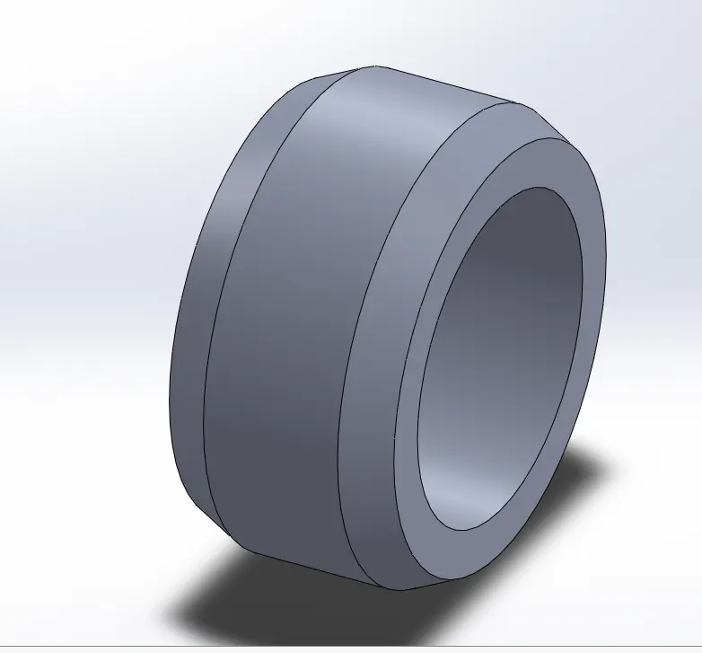
Revolve is used to make the hollow tubes. Adding the material by revolving a sketch around the axis. Note that the flat face required to make revolve your sketch. The axis is important for revolving the sketch because the sketch need to be revolved by selecting the axis
EXTRUDE CUT:
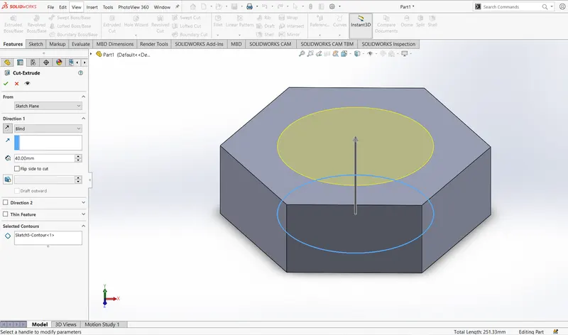
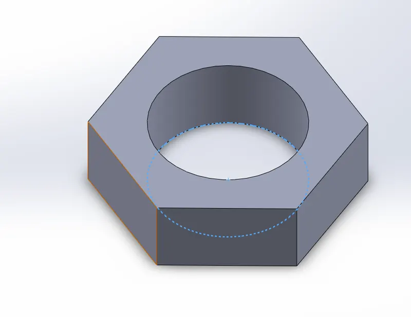
Extrude cut feature need to remove the material from the extrude component it’s similar to extrude boss feature and it is common tool for creating component of required shape.
SHELL:
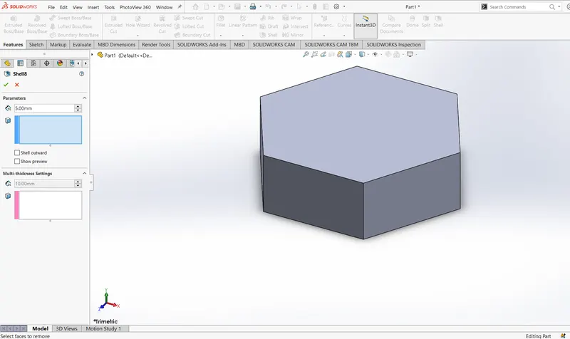
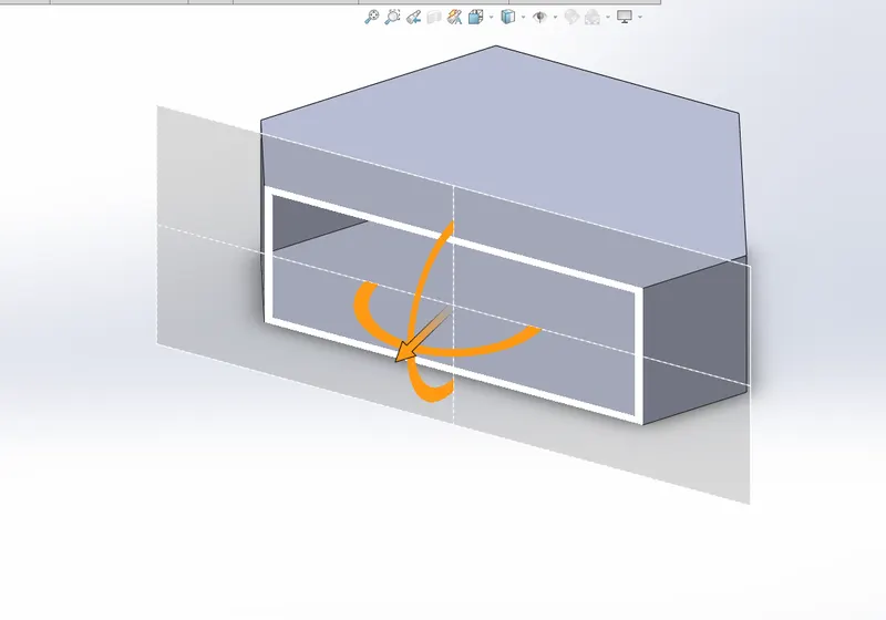
Shell tool is mainly used in solidworks for shelling process. It means to remove the inner material of the component. This not shown outer like extrude cut. To see the shell component by using section view. This view clearly shows how the component is after shelling.
SWEEP BOSS/SWEEP CUT:
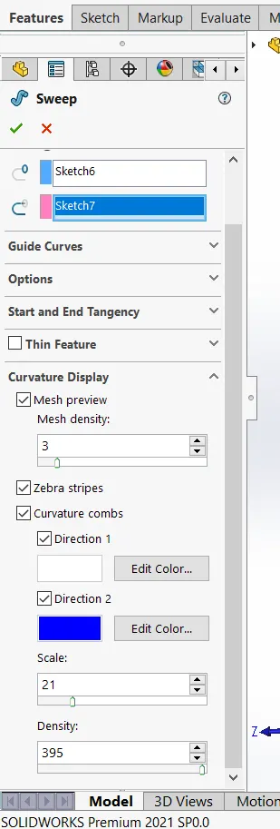
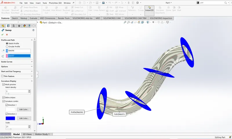
Sweep creates create boss, base and surface by moving a profile along the path. This feature many be open or close for a surface. For example, by creating sweep boss first sketch the part for sweep the select the sweep boss icon in feature tab. Then select face and the path for sweep after that use curvature display option. It shows how the sweep formed along the path.
LOFT BOSS/LOFT CUT:
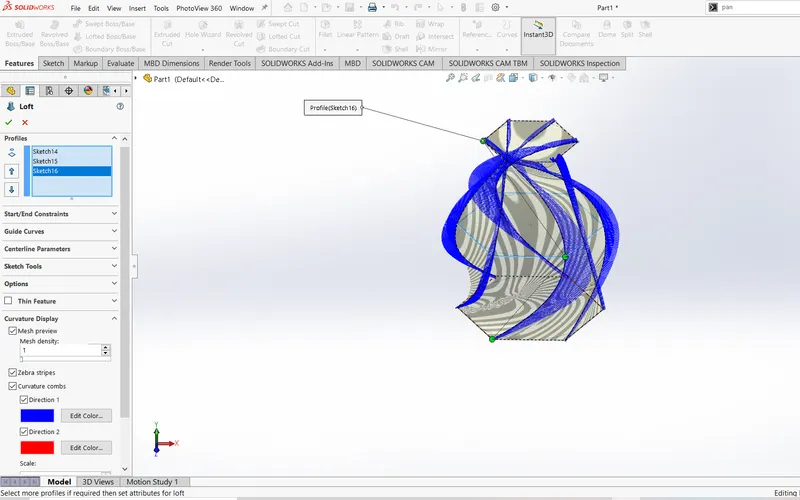
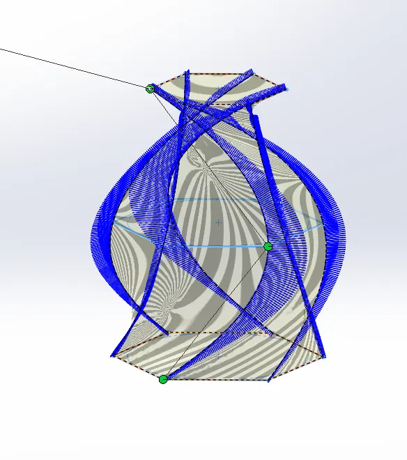
Loft boss is most important tool used in solidworks for modelling the part. Loft is to add material between two or more profile to create a solid feature. By select loft boss in feature tab and select the plane or sketch to loft then click curvature display option. It show’s how the loft formed between the two or mor bodies.
LINEAR PATTERN:
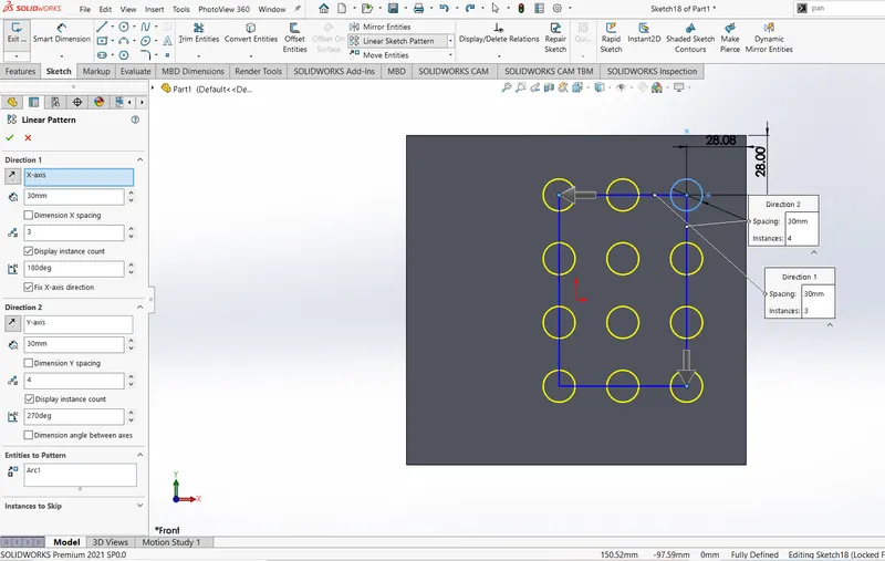
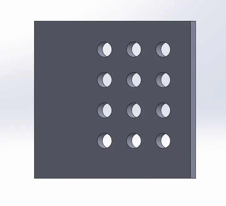
Linear pattern is to create multiple instances evenly by uniform spacing and angle. By crating two or more instances like hole, profile, etc. clicking linear pattern in sketch or in feature tab. Pattern instances inherit the visual properties of original feature. When you select propagate visual properties in properties manager.
MIRROR:
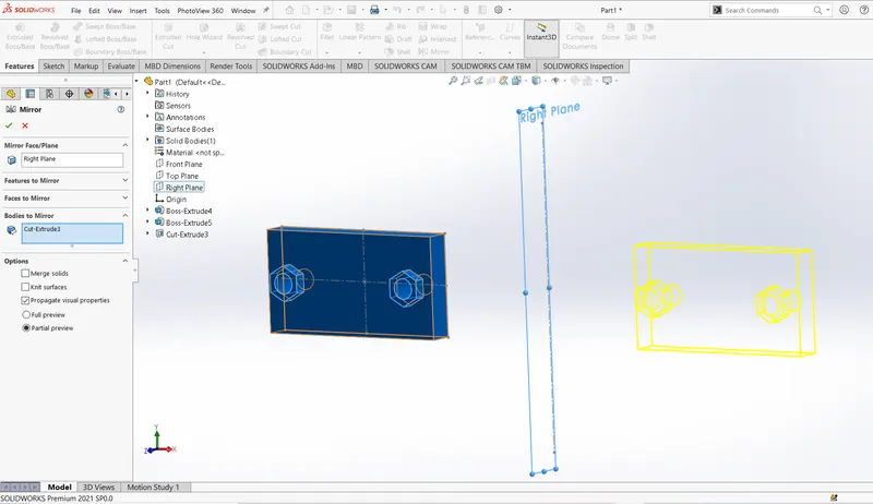
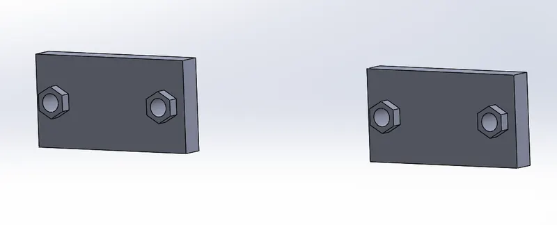
Mirror is quit commonly used in solidworks because you can create multiple features in single entity. Click mirror option in sketch or in feature tab, in sketch tab you can select the multiple lines in your sketch and also, select axis for mirror your part then click ok. In feature tab you can select your part and select the plane for mirroring then deselect merge and click ok.
REFERENCE GEOMETRY:
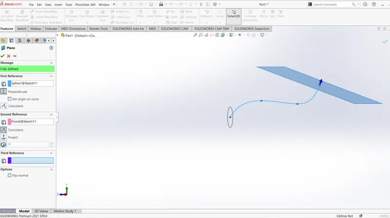
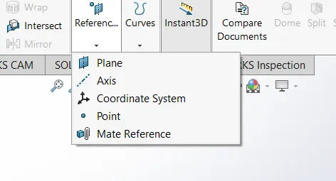
It means shape or form of the surface or a solid. The reference geometry includes some features they are plane, axis, point and coordinate system. With the help of reference geometry, you can create new plane or new part in you sketch. Reference geometry mostly used foe lofts, sweeps, circular pattern, and also for crating plane.
PROJECTED CURVE:
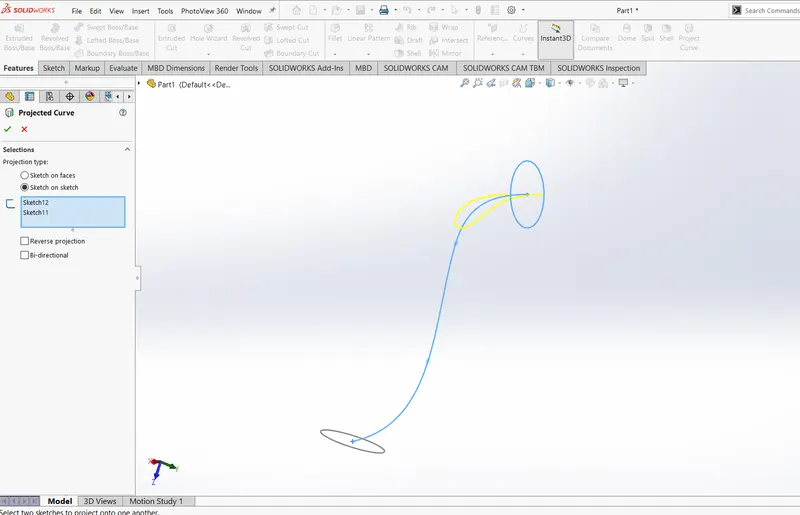
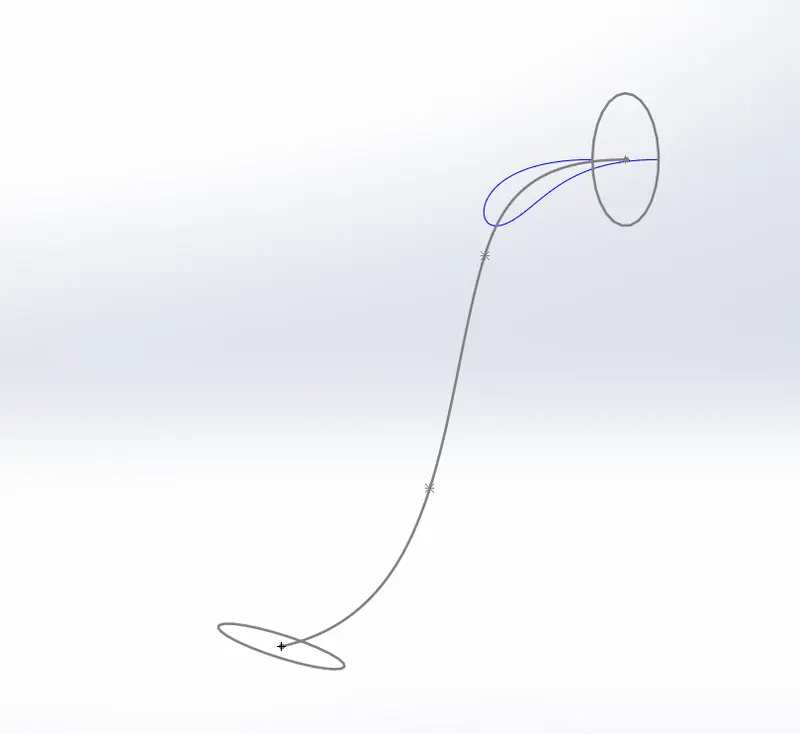
You can project curve from 2D and 3D, onto face or a plane. Project the curve select feature --> curve --> project curve. If creates a curve that represents the intersection of sketches from two intersecting planes. And also, you can use 3D sketch as input for projected curve tool. It does not support projection of intersecting curves.
MATE:
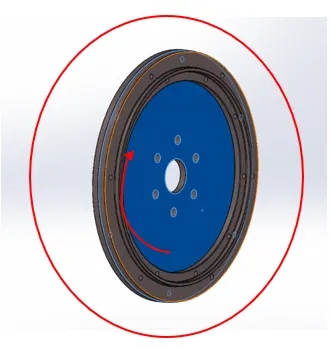
Mate is quit most commonly used tool in assembly section. It creates a geometric relationship between the assembled component. Applying mate on the component you can move within the degree of freedom (i.e., horizontal or vertical) for example, coincide relation two planar faces become coplanar. And a concentric means two circular (cylinder) face become concentric, this relation suitable only cylindrical components. By adding mates is not an issue, all mates are solved together and also you can suppress the mate.
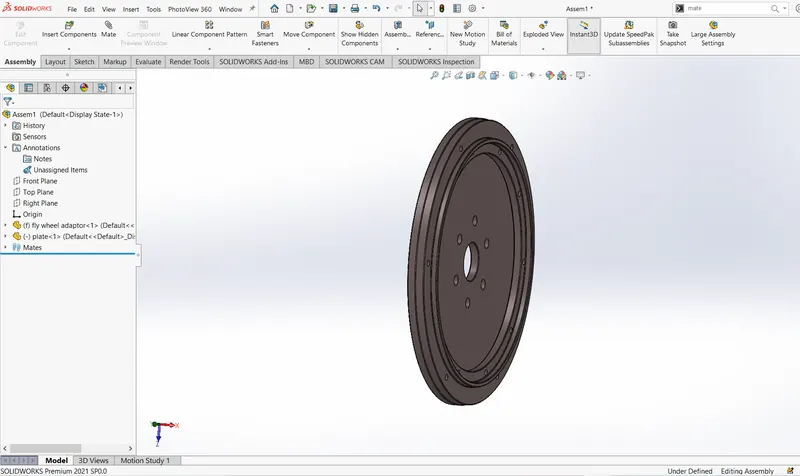
Discussion of the feature in solid works is finished. Let us see how this feature use to build chopper and how it works to crate parts for american chopper. Now we are going to look part by part as shown in the flowchart.
TRANSMISSION BELT:
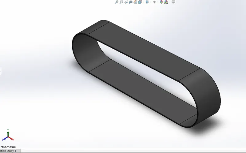
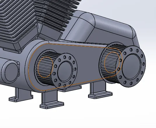
The solid body of transmission belt is a single extruded. The outer edge of transmission belt has been fitted with inner face of the engine and matte rubber used as the appearance for transmission belt.
KICKSTAND:
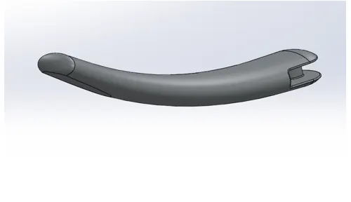
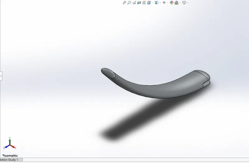
Creating the kickstand, we sued to make sketch based on additional plane and also that dome and loft used here in both ends and also, that the bottom of the kick stand make flatten surface which would rest on the ground. Here extrude cut also use for assemble it on chasses. Circular boss extrudes also used here and fillets are applied all edges, extrude boss and cut. Polished chrome used as appearance.
FRONT FENDRE:
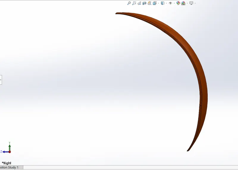
In front fender we use axis to revolve the sketch and here split options used in top and bottom of the fender then fillets are applied in all corners of the fender. Siena is used as the appearance for texture.
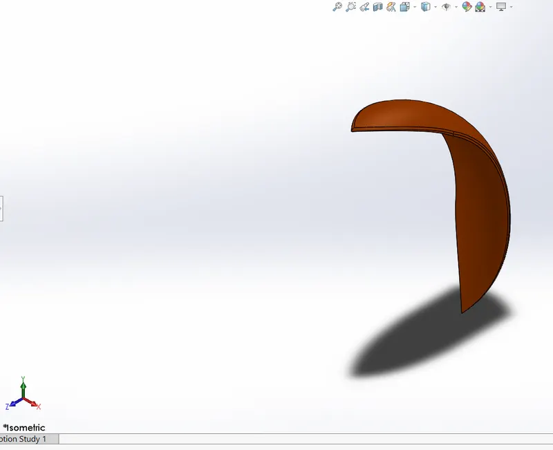
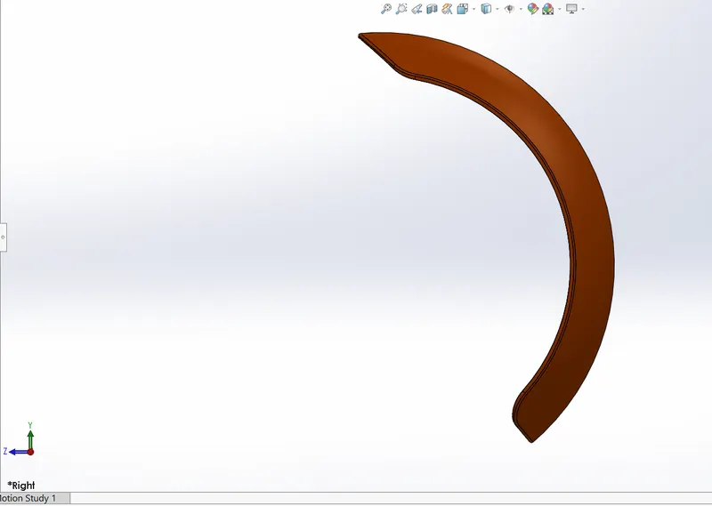
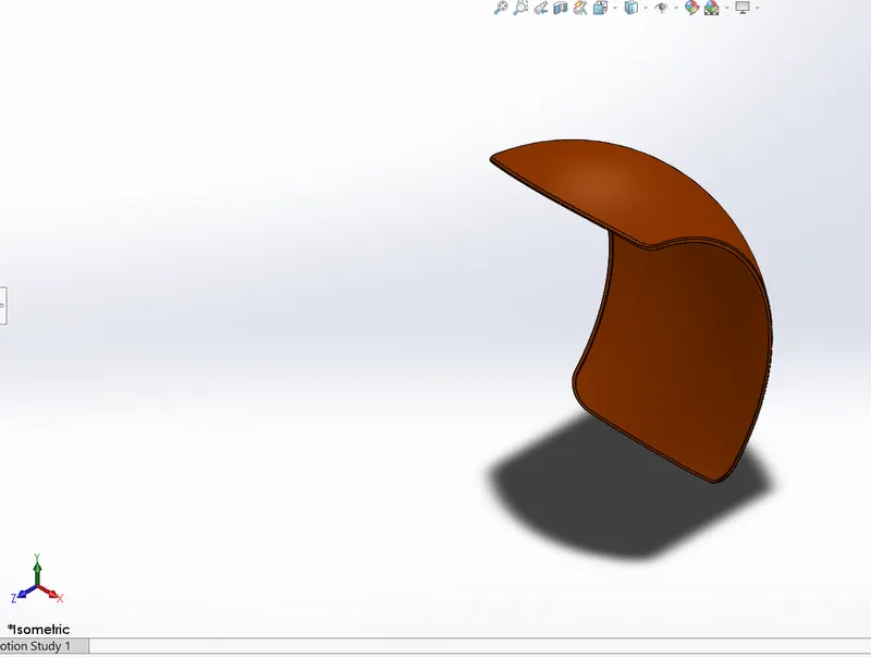
REAR FENDER:
In rear fender same method has been used for built the component. Then we compare to rear fender the size and the shape is much differ, due to the size of both wheels and also, that fillets are used in all edges. In rear fender only we use decals for environment and the same appearance is used for texture.
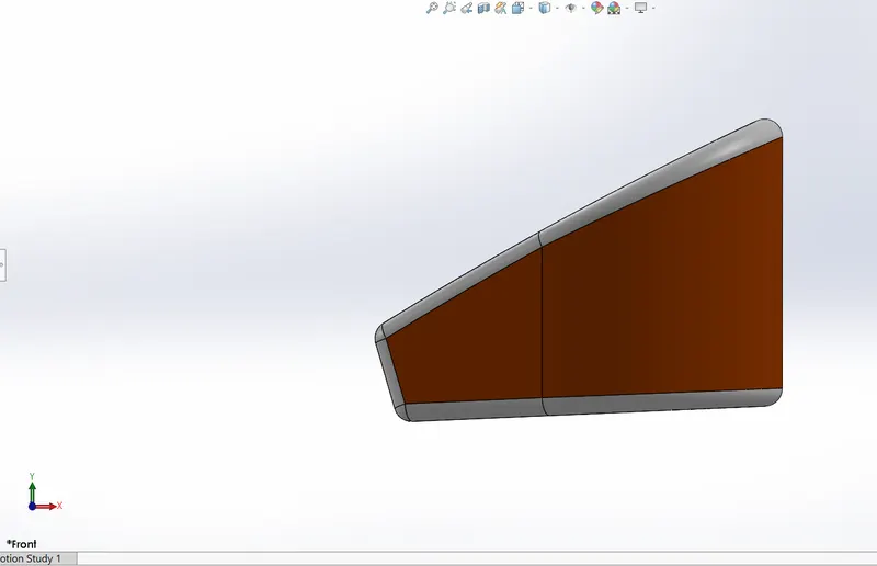
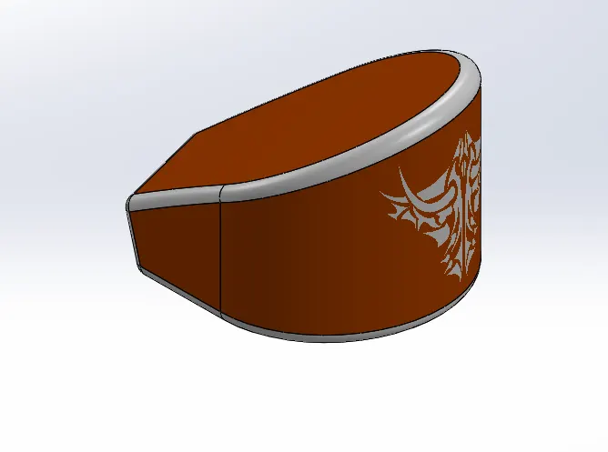
OIL TANK:
Boss extrude and shell features are used to crate the component. Before that the base of the oil tank is sketch on top plane then extrude isapplied. Then one more sketch is created on the mid plane and extrude the sketch after extruding combine feature is used to combine the both solid bodies in to one. Fillets are used in all edges of gas tank. Finally shell feature is used to make hollow inside. Section view is use to see how the shell option works. Then decals and siena used for texture.
CHAIN LINK:
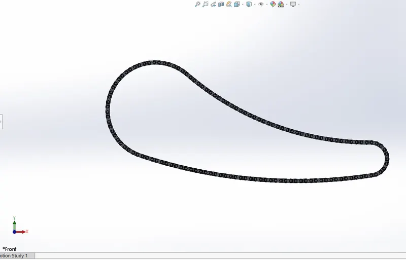
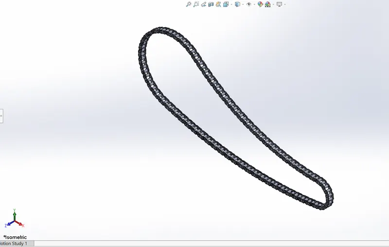
By create the chain with the help of arc and lines use as outline. Two chain links are crated and saved for creating chain. Insert the two block diagrams previously saved. Make the links concentric and tangent to the lines. Then use linear pattern for crate multiple chain blocks uniformly in the outline. After that insert the links for path arrangement because, the linear pattern does not provide a clean path arrangement in curve section. This method is used for entire loop to complete the chain link. Mirror feature is used in face of the links to the pins. This entire solid body is respected in midplane. Chrome plate is used as the appearance.
PEDAL:
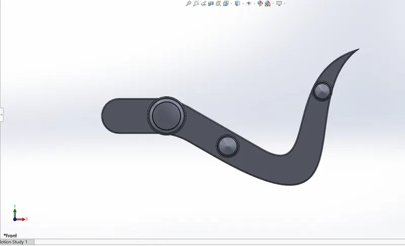
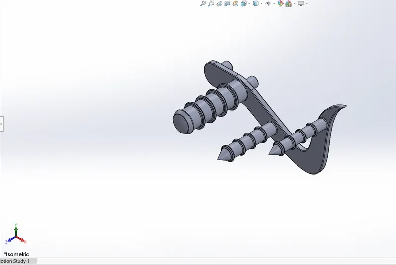
The sketch started with front plane because the base of the pedal has been outlaying. In creating pedal extrude boss, mirror, splines are used. Extrude is used to create the pedal with circle for foot rest then extrude the circle then fillet is applied in all edges to avoid sharp cuts dome feature is used in the edge of foot rest and chamfer use to give a proper finish on each circle. Then circular patten used to extrude on each of the front facing extrudes. Linear pattern used to arrange the extrudes. Finally polished chrome use as the appearance for texture.
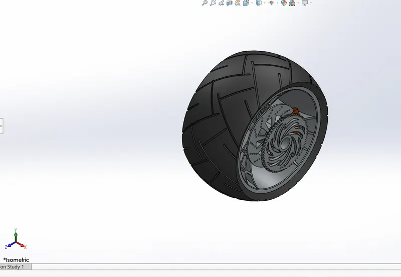
FRONT WHEEL:
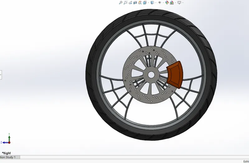
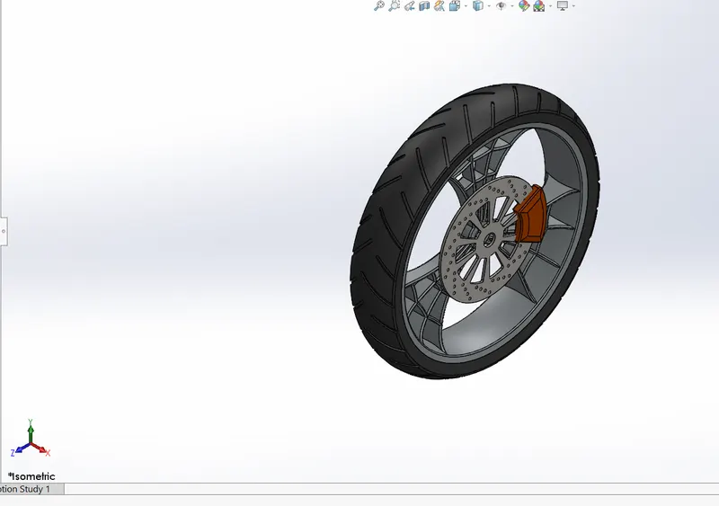
Infront wheel the we use revolve the sketch along the axis after that boss extrude, convert entities, trim and extend entity features are used to create frocks. After crating the frocks circular pattern use to create multiple entities. Then combine the forks by using combine feature. Brake caliper and disc is crated the concentric relation applied on the disc linear and circular pattern used to finish the disc and also that circle option and trim feature use to create brake caliper. Fillets applied in all corners. Corner rectangles use to create grip on the tire finally matte rubber, chrome and siena appearance used in the wheel.
REAR WHEEL:
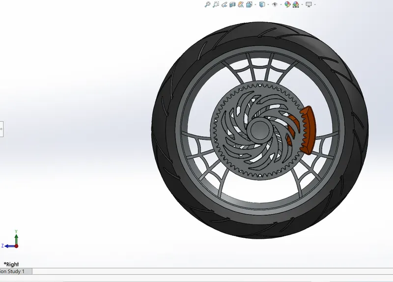
The rear wheel is much similar to front wheel so the same method is used to create the rear wheel. But the rear wheel sprocket is created with the help of line and circle is used. Offset option is used, because the sprocket is place before the face of break disc, fillets are used to remove corner edges. Chamfer option also used for crating the part on the rear wheel. Finally, siena, polished chrome appearance used for texture.
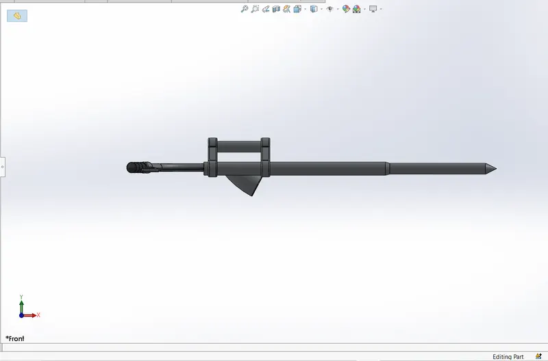
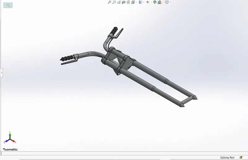
FRONT FORKS:
Front forks consist of head light, handle bar, break wire, clutch lever and handle grip. First sketch the fork in front pane and revolve it. Then draw the sketch on top plan for headlight, extrude the sketch by using extrude sketch feature after that mirror option use to mirror the selected sketch. Another extrude has been done for handle after that another revolve has been done for handle grip. Create a plane for sketch the break wire by using splines, curve feature used to crate break wire on the face of handle. Sweep has done for break wire. Before that select reference plane used to create break lever, sketch the part and extrude it, after creating all component combine option is used to make multiple solid bodies in to single solid body then give appearance in brake cables, handle grip matte rubber is used and remaining parts polished chrome is used. Area light appearance is used only for light. In this part fillet and dome is used. Fillet used for remove corner edge and domes used for light.
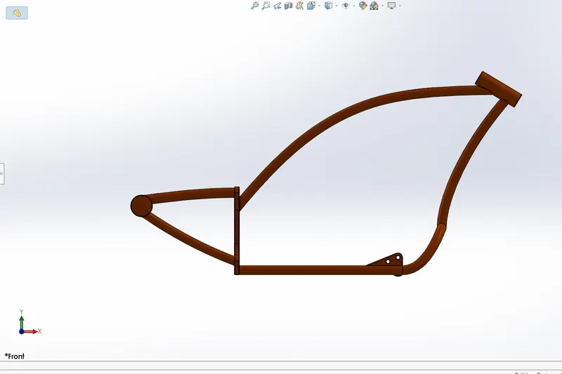
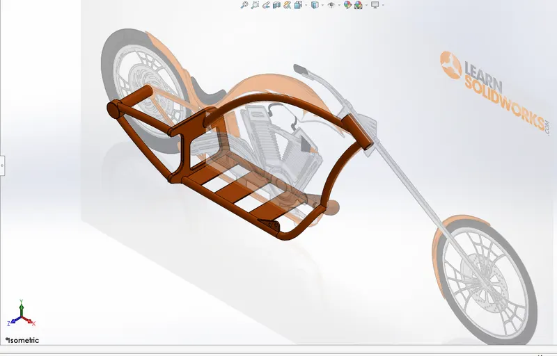
CHASSIS:
Chassis is the main component of all vehicle. Place the chopper blueprint by using tool -->sketch tool-->sketch picture and ok. This sketch begins with two projected curves to attain lower curve path sweep is used to make the hollow shaft, after that mirror feature sketch the part for engine mounting, pedal and kickstand mounting. Sketch the block and make extrude after that extrude cut used to remove material from the sketch. Then draw the hallow shaft for handle bar mounting on new created plane (Reference plane-->plan-->ok) and also, draw the sketch for gas mounting bar by using splines and split tool used to remove the extra bar from the back face of the block. Combine option used to combine all components all sketched and extruded components should be fully define camper the bottom edge of the block finally sketch the line and revolve it. Dome is used one edge of the shaft. Section view also used to see the joint in hallow shaft from chassis. After all components are created give fillet for removing sharp edges in chassis. Finally give siena appearance in chassis for texture. Also, that plane is added in chasse for further assembly purpose.
ENGINE, MOTOR AND EXHAUST SYSTEM:
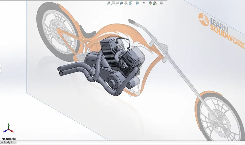
Creating engine part, the sketch is made on front plane and the exhaust. First crate base part of motor circle and line used to make the part extrude boss and fillet are applied.
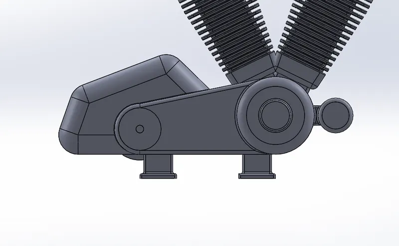
Then backside of the motor two revolve are made for transmission belt with the help of line the revolve created. After creating revolve draw teeth for belt in the cylinder component. Make extrude the sketch and circular pattern used to create multiple instance (teeth). Spokes is also made for chain by using linear patter in circular region. Create cylinder in front of the engine then extrude it of desire shape.
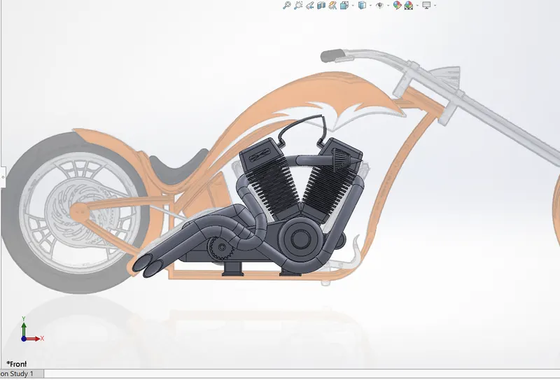
Top of the motor the engine case and the top of the case is create after that extrude the step by step and merged with entire body. By creating the fins on the case by cut out engine body from entire body and multiple linear patterns used to make the fins then fillets and chamfer are used. Top a sketch is done and spark is created with the shape of the engine then mirrored is done for twin cylinder. Now front gear is created for chain link, extrude is used to done the part. Move to exhaust pump. Multiple splines, tangent and concentric relation used for creating this part, the two projective curves are made then the both curves joined together form a composite curve sweep the curve in between the engines. The same process as done for another exhaust pipe. Apply fillets for removing the sharp edges from engine. Now move to spark plug wire the sketch as done top side face of the engine after creating the sketch two different sweeps used to built the part. Finally apply polished chrome appearance for texture.
GAS TANK:
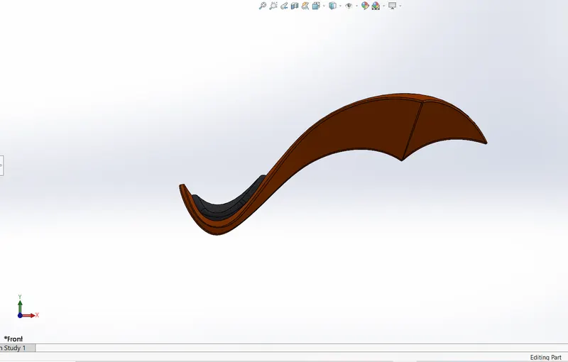
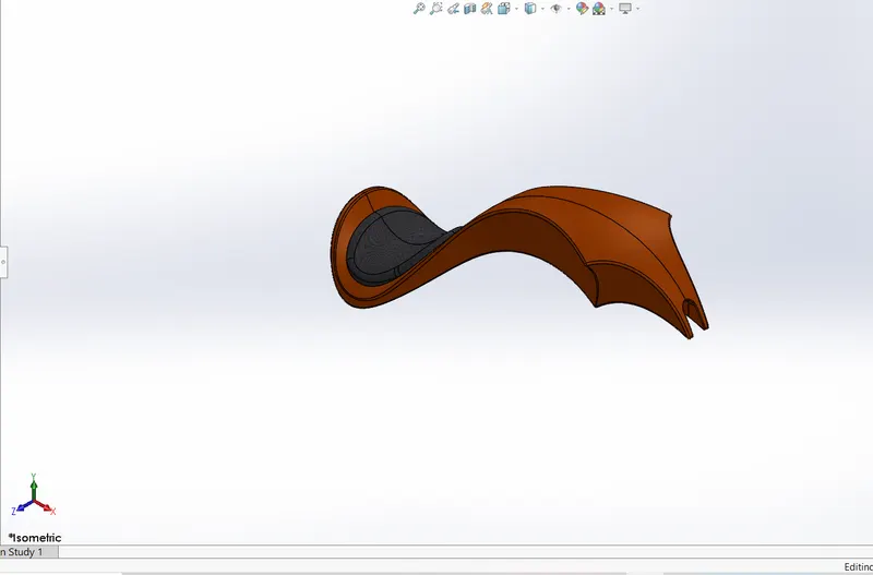
In gas tank part additional reference plane, sweep used to create the layout of gas tank. The edge of the gas tank surface is trimmed and one more plan is added, this component create with splines. The surface loft is created as the front face of the tank now joined together. Mirror feature is used to create another instance. After mirroring the sketch now, the entire part and knitting them together for gas tank structure. The rear end seat is created by extruding the surface and applying the fillet on the edges of the seat to give a round off look. The surface loft and knitting tool used to covering the bottom of gas tank. The sketch as drawn at the face of gas tank for make u cut section. After creating the gas tank decals are applied in side and top of the gas tank. Before applying decals combine option used to combine the parts in single solid body. Finally, siena applied on the gas tank and gray cotton material applied in the seat for texture.
We complete the decision of following parts for american chopper how to create the part and how apply appearance for those parts. Now move to assembly section.
In assembly section we can use mate, insert component and some relation like tangent, concentric, coincide, etc. assembly section only we can see how the model comes. Let us see the assembly.
ASSEMBLY:
After making all components for chopper, the most important part of assembly the whole part starts with single file. First insert chassis and place it on front plane after that insert engine at right place then make coincident the front plane of engine and chassis front plane. Select mate and select bottom corner of flat in chassis and bottom of the stand in engine then give some value to mate. Insert pedal place it on correct place gives concentric relation on the pedal and the hole present in chassis after give coincident relation after mate the pedal use mirror feature to mirror the pedal on another side of the chassis. Again, inset kick stand and place it on correct position and give mate option between the face extrude cut face and the chassis after give concentric and tangent relation for mate and give limit angel for kick stand because it freely moves over 3600 by giving limit angle of 300. Insert transmission belt make concentric of front plane in chassis and belt front plane then give mate select the face of transmission belt and the inner face of the revolve in motor, select tangent then ok. Again, select top face of motor and the top face of the belt give some angle not it’s completely mate with engine. Float the chassis now look the mated components it does not move separately it will move along chassis. Then the same thing done for oil tank after inserting oil tank insert rear wheel place it and make concentric of inner face of the sprocket and the chassis give mate. Now insert chain link give relation to mate with sprocket in motor and the rear wheel here tangent relation is applied for chain because it gives proper seating of the chain and the sprocket. Insert gas tank place it on correct position give mate before that give coincident relation of gas tank and the chassis follow by plane. Note, check all components are fully
defined by fix the chassis. Insert front fork in that front fork select face and the chassis give a relation after that use mate feature give tangent relation after making mate insert front wheel the same process is done by previously done relation for back wheel. Finally insert fender give some relation and use mate feature. In assembly section we edit the appearance but in part level.
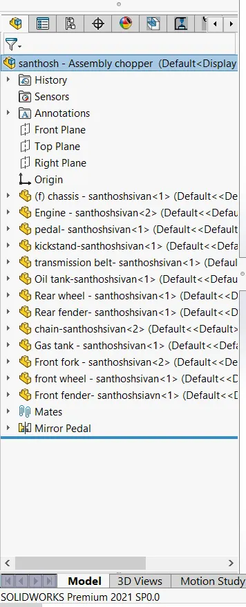
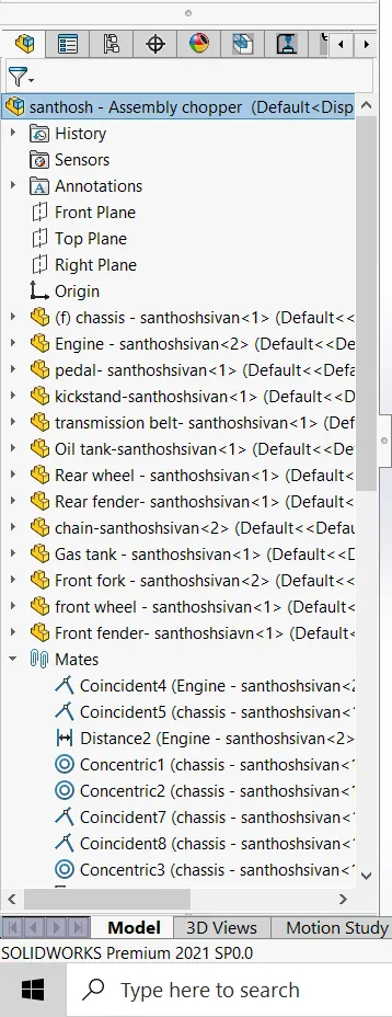
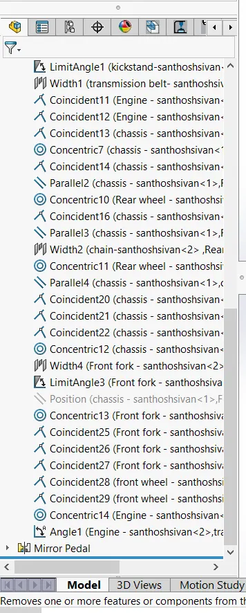
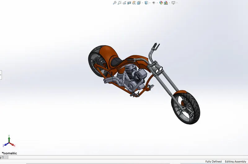
Assembly section is completed all components are fully defined in assembly. Now move to rendering part.
RENDERING:
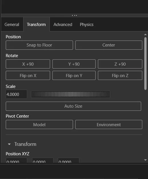
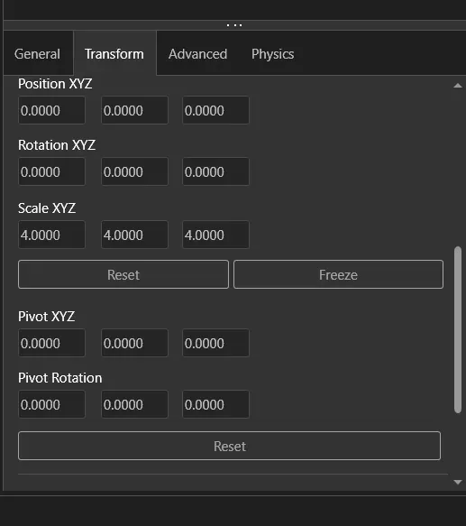
Rendering is the final stage. Rendering gives a realistic look for our chopper previously discussed about rendering. Here we look how we render our chopper of different environment. First apply tangent relation to front and rear wheel then give a relation in kick stand because, the chopper snap to floor properly. Now use camera and perspective feature for our chopper in camera view we know the stylish then add decals on rear fender oil tank and gas tank for extra texture if you already applied decals don’t add decals in rendering. The camera view setting the desire lights and the focal distance creating the angle of view. Saving the camera angle which gives a realistic view of our chopper. Then move our chopper file into solid work visualize. In that we add more realistic of our chopper. Make sure inserting your component select snap to floor, after that inset environment by select scene-->add environment-->select-->ok. After inserting background scene adjust gamma value. After that go camera adjust brightness and rotate component for your view and lightning then go to transform use perspective option adjust the view and also use longitude and latitude option for view. The lightning position as change by rotating your background after all go to output tool change the name and use browse option for save your file then select the ratio for your image. Select rendering type whether png or jpeg file. Click accurate option and select quality then give render passes according to your system requirements. If you give more passes it takes much time to complete. Click ok now the rendering starts.