Radar Mast & Final Assembly of Yacht
1.RADAR MAST
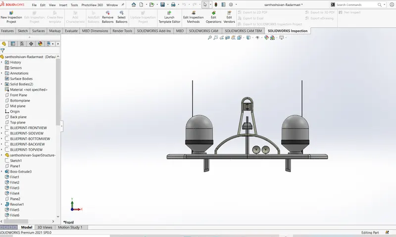
1.Front view
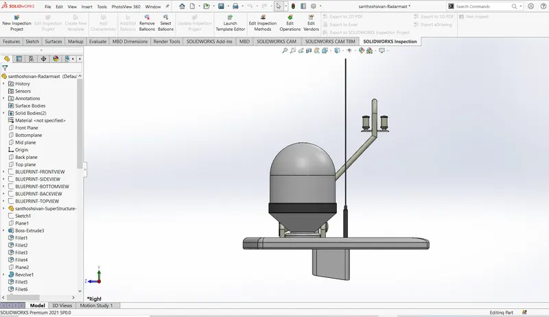
2.Right side view
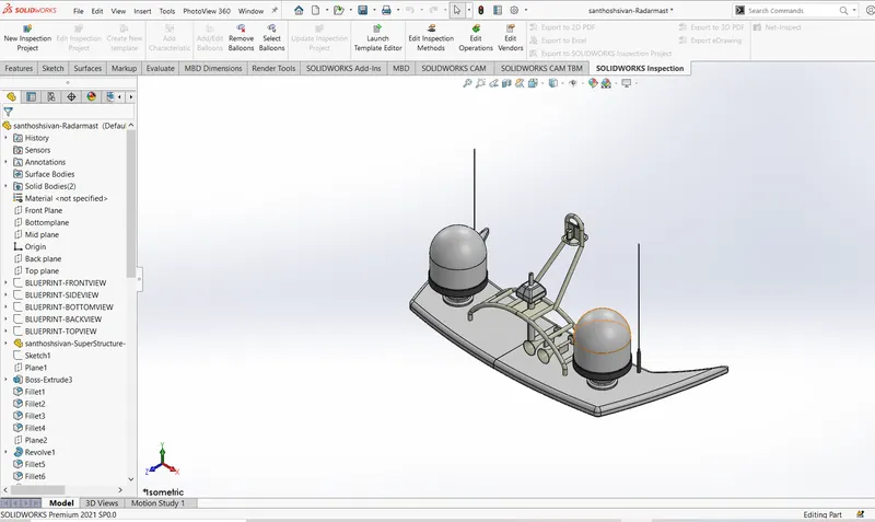
3.Isometric view
4.History tree 1
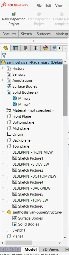
5.History tree 2
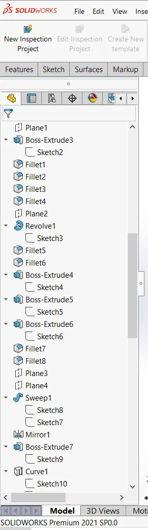
6.History tree 3
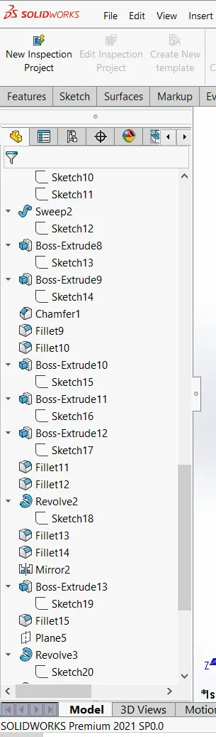
7.History tree 4
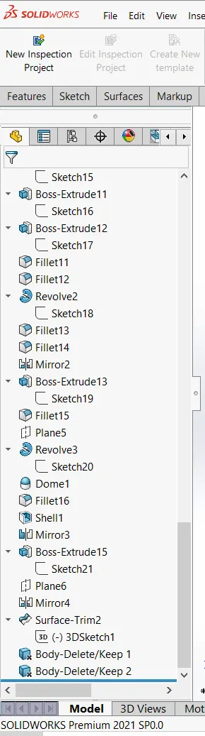
2.YACHT ASSEMBLY
Modelling of yacht tutorial on solid works
By
Santhoshsivan.G
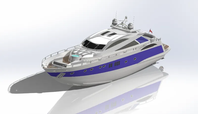
Introduction
In this project we are learn to sketch entire model of yatch tutorial on solid works by using some tools like surface loft, extrude boss, extrude cut, surface fill, etc and also, we learn how to render the yatch model by using solid works visualization.
This are some different components used to create yatch as mentioned below.
- Propeller
- Radar
- Blue print
- Hull
- Garage door
- Front seat
- Middle seat
- Rear seat
- Super structure
- Radarmast
After creating all part components, move to assembly and photo rendering for yatch which gives it a complete and realistic view of yatch by using solid works visualize.
In this project we are learn to sketch entire model of yatch tutorial on solid works by using some tools like surface loft, extrude boss, extrude cut, surface fill, etc and also, we learn how to render the yatch model by using solid works visualization.
This are some different components used to create yatch as mentioned below.
- Propeller
- Radar
- Blue print
- Hull
- Garage door
- Front seat
- Middle seat
- Rear seat
- Super structure
- Radarmast
After creating all part components, move to assembly and photo rendering for yatch which gives it a complete and realistic view of yatch by using solid works visualize.
Design approach flow chart
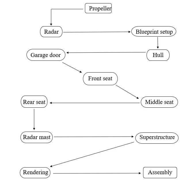
The below flow chart shows the process of creating yatch in step by step. First it starts with propeller and end with rendering.
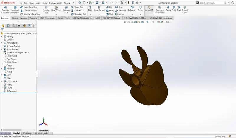
1.Propeller:
A propeller means to rotating and move the hub by radiating blades that are set at a pitch to form a helical spiral, when rotated, exerts liner thrust upon working fluid such as water and air.
This component used in pump, duct and turbine by creating thrust to move the boat in water and move the aircraft in air. These blades are specially designed rotational motion by creating a pressure of two different surfaces of the blade by Bernoulli’s principle (Means to increase the speed of a fluid occurs simultaneously with decrease a pressure of fluid potential energy). Most of marine propellers are fixed with helical blades rotating on a propeller shaft with an approximately horizontal axis.
- Revolve:
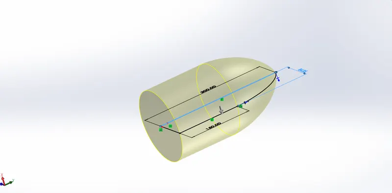
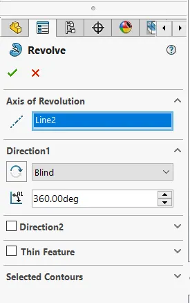
Create a sketch and click Revolve Boss/Base in feature tab or simply click Insert--> Boss/Base--> Revolve the axis for revolve. In revolve box select the sketch and select the axis for revolve. Because an axis to create a revolve feature.
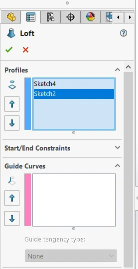
B.Loft:
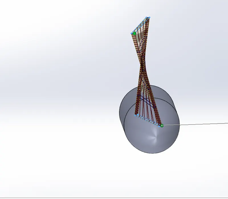
Loft feature on solid works allow us the generate geometry in a single feature. Click loft in feature tab or simply go to Insert-->Base/Boss-->loft. After that click sketch for profile and also click sketch for guide curve and click ok.
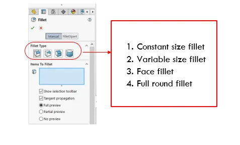
C.Fillet:
Fillet/Round feature use to remove sharp edges from the sketch after creating.
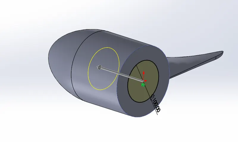
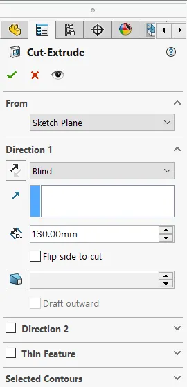
D.Cut extrude:
For creating a cut extrude. Sketch the part and click cut extrude in feature tab or go to Insert-->cut-->Extrude on menu bar.
E.Circular Pattern:
Circular pattern used to create multiple instances of uniformly around the axis. To create circular pattern, click circular pattern in feature tab or go to Insert-->Pattern/mirror-->Circular pattern. Select sketch and click ok. Finally give appearance in propeller.
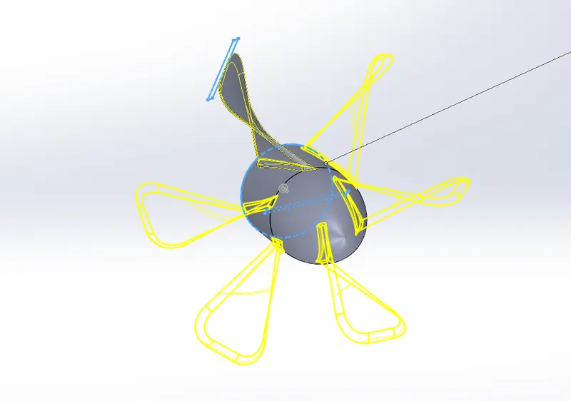
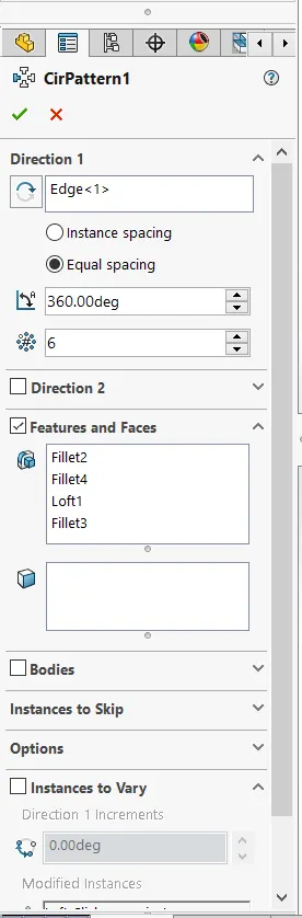
Propeller:
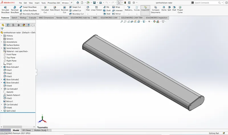
2.Radar:
Radar is nothing but to locate other ships, land obstacles and also for telecommunication. It gives exact information for collision avoidance and navigation while on water. Marine radar act as a major roll for navigation aid for boaters.
In this model we use boss/base extrude, cut extrude, fillet, mirror, sketch pattern and split line etc.
- Extrude boss/base:
For extrude boss/base. Click Extrude Boss/Base or simply click insert-->Boss/Base-->Extrude on main menu. Then select the sketch for extrude and click ok. After that click extrude cut or simply click Insert-->Cut-->Extrude.
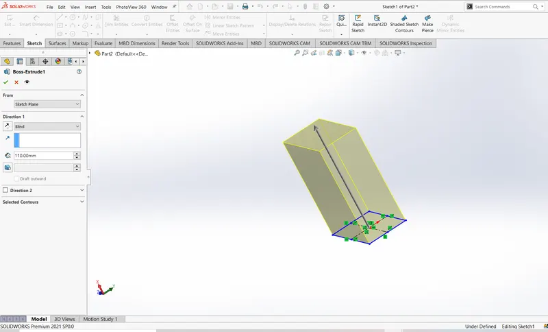
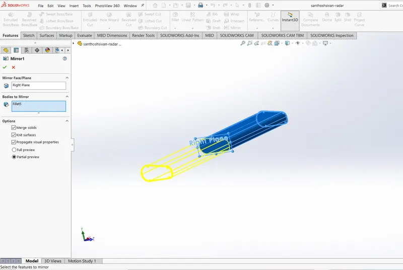
B.Mirror:
Mirror means to create multiple instances by using face or axis. For mirror click mirror option or simply select Insert-->Pattern/Mirror--> Mirror. Select the sketch and select the face or plan to be mirror.
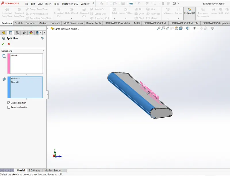
C.Split line:
Split line means to project the sketched lines onto selected face and divide it into multiple regions as define by sketch. After creating a split line, it has different appearance than the other region and function as separate face.
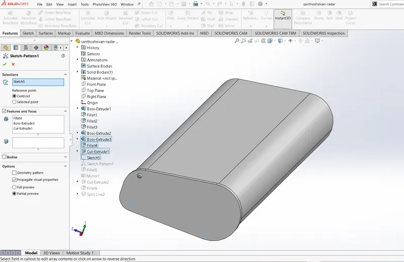
D.Sketch driven pattern:
In sketch driven pattern, create seed feature on the model. Click sketch driven pattern or simply click ToolsàSketch EntityàPoint, and add sketch points to done a pattern, based on the seed feature.
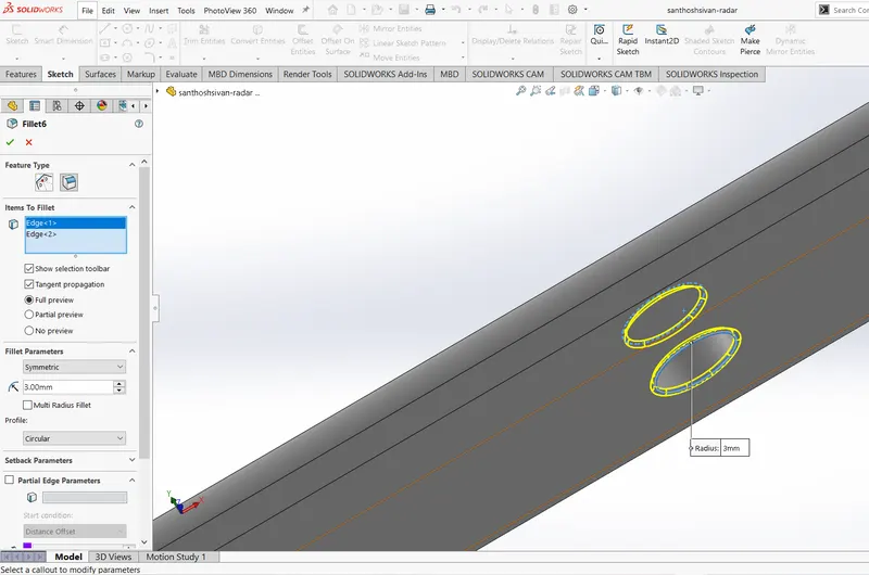
E.Fillet:
Fillet means to remove sharp edged from the sketch after done the pattern, extrude sketch or extrude cut. Finally give some appearance on face or body.
Radar:
3.Blueprint setup:
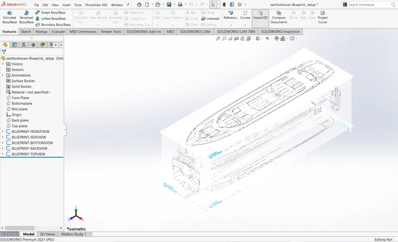
Let’s see how to setting up blueprint for yatch in solidworks?
First select new plane. Then add picture by click Tools-->Sketch tools-->Sketch picture, then select blur print and enter value then rename and click ok. This process should do for all blue prints.
4.Hull:
Hull is the most important (notable) structural entity of our ship. To define the hull, its id watertight enclosure of ship, which protects the cargo, machinery parts, food, structural damage, people and space of the ship from weather. In this model different types of features are used. They are,
A.Project curve:
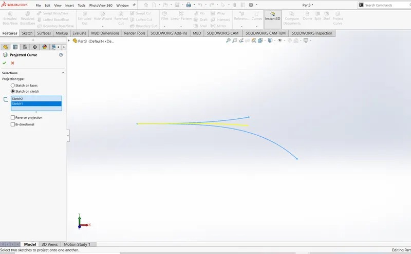
Project curve means project curve from 2D and 3D sketches, on to faces and plane Selects the direction of projection as an axis, linear sketch entity, linear edge, plane, or a planar face. To create curve by click the project curve or select Insert-->Curv-->Projected.
In selection select both the sketch and click ok.
B.Surface loft:
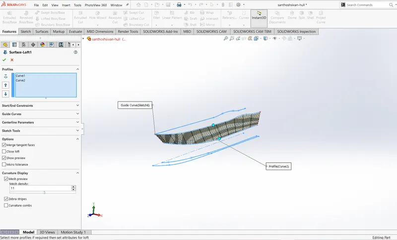
To create a surface loft, create a plane for profile section of the loft. Note that the planes not needed to be parallel then sketch the profile for loft on the plane and click lofted surface or select insert-->Surface-->Loft. Select the sketches and click ok.
C.Surface trim:
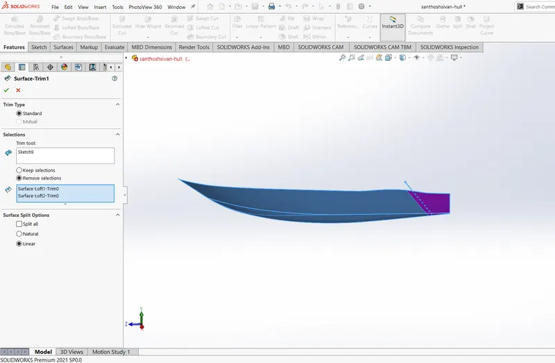
In surface trim define as to remove the excess material from the sketch by intersecting to surface. Create two surface that should be intersect with plane or has a sketch on its plane. Click trim surface or select Insert-->Surface-->Trim. In trim property manager they are two types of option, one is standard and another one is mutual. In standard trim the surface by using curves, planes and other entities. But in mutual multiple surfaces required for trim.
Another two option is there under the selection, one is trim tool and another one is surface. In trim tool trim the surface by using curve, plane and some other entities. In surface trim use multiple surfaces for trim. Then two types of action are there for trim. Frist one is keep selection and another one is removed selection.
In keep selection the select surface cannot remove but in remove selection option removed the select sketch from the surface.
If you are selecting mutual trim, the preview option is available. As shown below and select on those following:
|
Show included surfaces |
Displays the regions that you are including as surfaces. All other surfaces are hidden. |
|
|
Show excluded surfaces |
Displays the surfaces that you are excluding as transparent. All other surfaces are hidden. |
|
|
Show both included and excluded surfaces |
Displays both included and excluded surfaces. Excluded surfaces appear transparent. |
Under surface split option select either natural or linear boundaries. Natural boundaries extend the tangent from end of trim tool and in linear boundaries extend it from trim tool endpoint to the nearest edge. Select split all its optional and click ok.
D.Surface extrude:
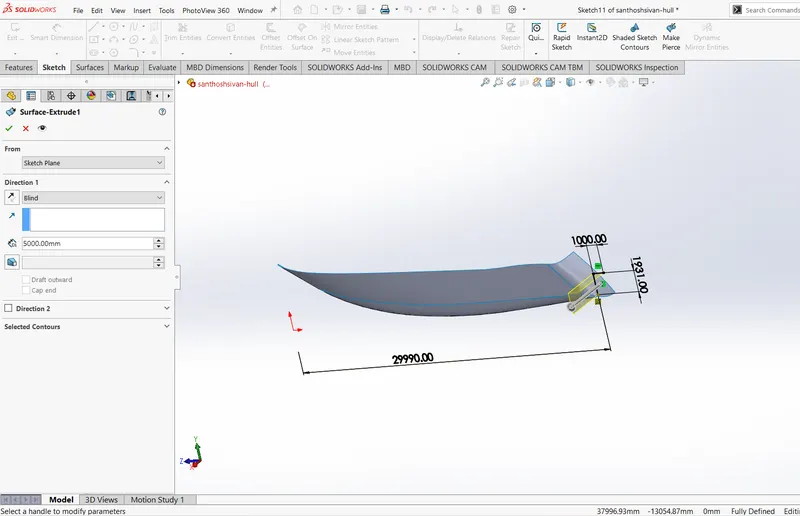
Surface extrude means to extend the selected or sketched surface from the plane. For 3D face select a plane, line,2D face and some other entity. Click surface extrude or select, Insert-->Surface-->Extrude and select line or sketch or 2D face, finally click ok.
E.Shell:
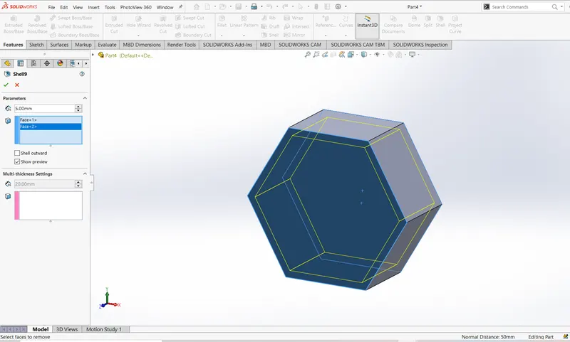
In shell tool is to make hallow out a part, it creates thin-walled feature on the remaining faces. Select shell feature or select Insert-->Feature-->Shell. In shell property manager select face to be shell and click ok.
F.Chamfer:
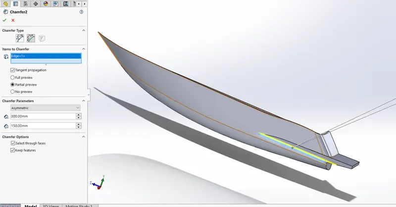
Chamfer means the tool to creates a beveled features on selected edges, faces, or a vertex. To create chamfer click fillet under chamfer or select Insert-->featur-->chamfer, in chamfer properties manager select sketch and give some value as per diagram and click ok.
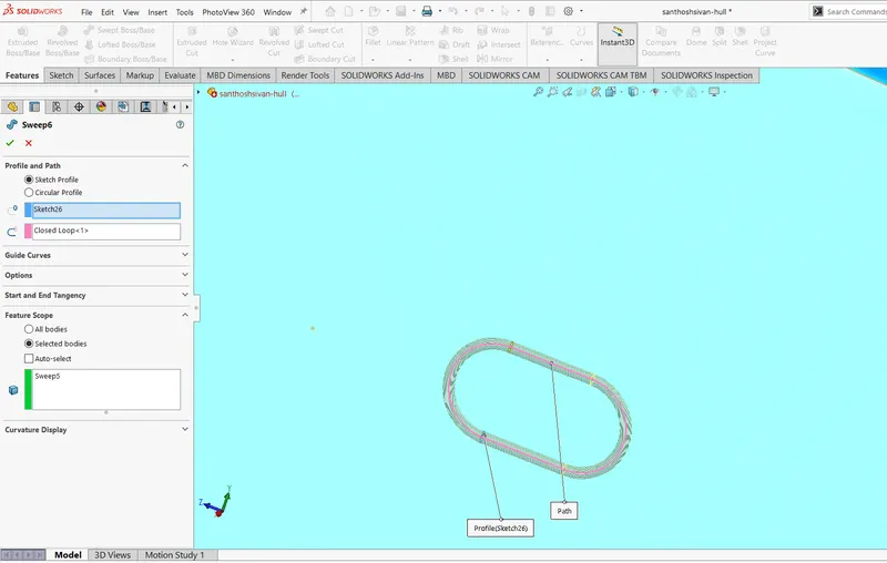
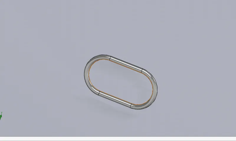
Sweep:
To create sweep by click sweep on feature or select Insert-->Boss/Base-->Sweep. Select the sketch and select guide curve and click ok. Note that the guide curve should be close, non-intersecting profile on a plane or a face.
 H.Dome:
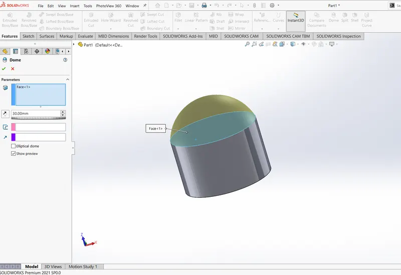
Dome means add one or more dome to select planer or non-planer faces. To create dome, select dome on feature tab or select Insert-->Feature-->Dome. After that set a value of the distance by which the dome as expands. And click ok.
I.Linear Pattern:
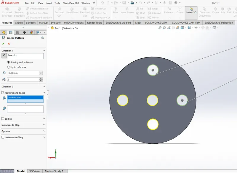
Linear pattern means to create multiple instances that you can uniformly distance and angle along one or more linear paths. To create linear pattern, select linear pattern or select Insert-->Pattern-->Linear pattern. Then enter the value for direction 1 (X-axis) and direction 2 (y-axis), angle after selecting the sketch for pattern. Then click ok.
J.Combine:
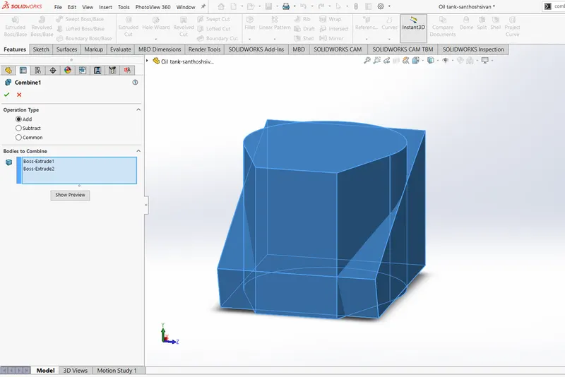
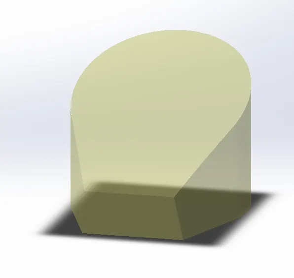
Combine means convert two sketches into single body entity by selecting the sketch. Click combine option in feature or select Insert-->Feature-->combine. In combine property manager, select add and click ok.
k.Helix/Spiral:
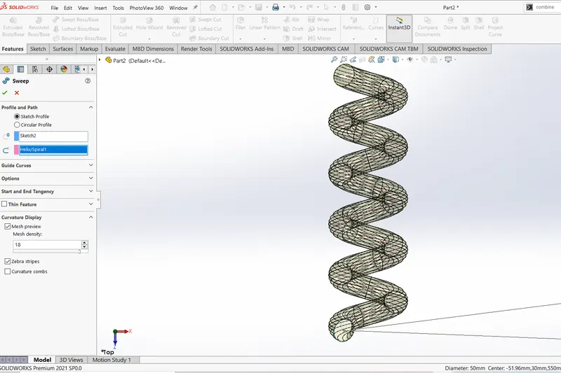
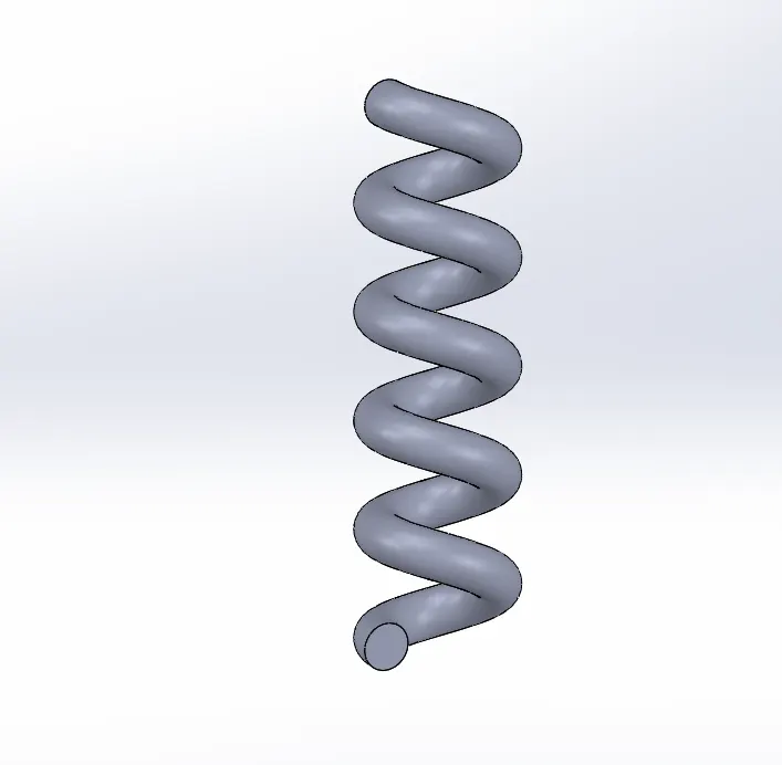
The diameter of the circle controls the starting diameter of the helix or spiral. To create helix/Spiral or select Insert--> Curve--> Helix/Spiral and select the sketch then click ok.
L.Move/copy/delete the body:
In move/copy/delete feature means to move, copy and rotate solid or surface body. Click move/copy bodies in feature tab or select Insert-->Feature-->Move/Copy. Apply mates between bodies.
In Delete/keep body feature means to remove or keep the sketch. Click insert-->Feature-->Delete/Keep body or click Delete/Keep. In property manager, delete body to remove the selected entity from the sketch and keep body is to keep the selected entity. For bodies to keep or bodies to delete, select bodies in the graphics area or from the solid bodies folder for solid/surface bodies to delete/keep and click ok. Finally give appearance for hull.
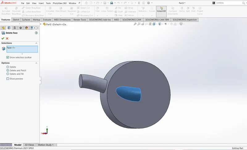
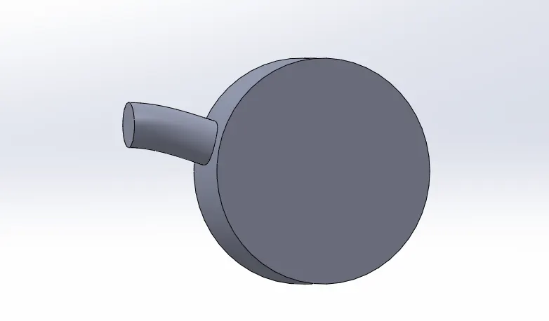
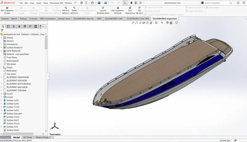
Modelling of hull:
5.Garage door:
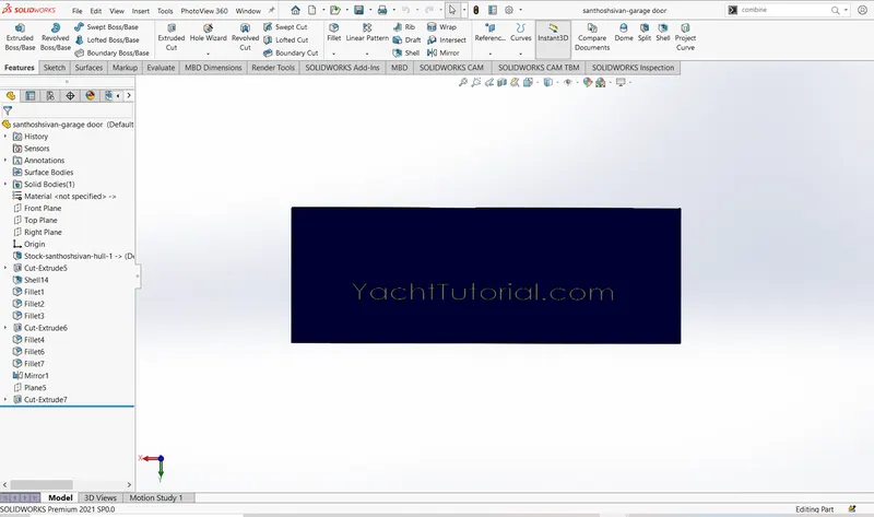
The purpose of garage door is to accommodate automobiles and some other vehicle and it is a large door on a garage that open manually or by using electric motor. In garage door modelling they are some features are used for cerate, the different features are extruded boss, extrude cut, fillet, split line, etc. Finally give appearance for garage door.
6.Superstructure:
Modeling of superstructure we can use lot of tools and features and previously we know some tools and features are used and how it’s works by modeling of hull. But in superstructure we lookover some feature and its usage as following below.
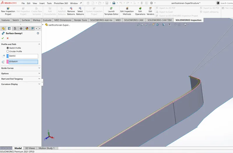
A.Surface sweep:
Surface sweep means surface that are generated from a section curve positioned along a path and maintaining the section curve to be parallel to the guide path. For creating surface sweep click surface sweep or select Insert-->surface-->sweep. Then set property manager and select the sketch. Then click ok.
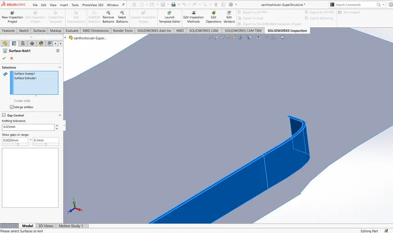
B.Surface knit:
Surface knit means to combine two or more faces into single surface. In surface sweep note that the edge of the surface must be adjacent and not over lapping, do not need to be on same plane. For surface knit click surface knit or select Insert-->Surface-->Surface knit. In surface knit property manager select the surface (note: The selected surface should not be knitted). Click merge entity, which means merge faces with the same underlying geometry. Select gap control to view the gaps between two surfaces or modify the knitting tolerance.
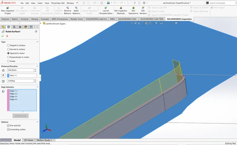
C.Ruled surface:
Ruled surface means the tangent to the surface that share an edge. Ruled surface is normal to the surface that share an edge. To create ruled surface by click ruled surface on feature or Insert-->Molds-->ruled surface. In property manager select edge and give the value and click ok.
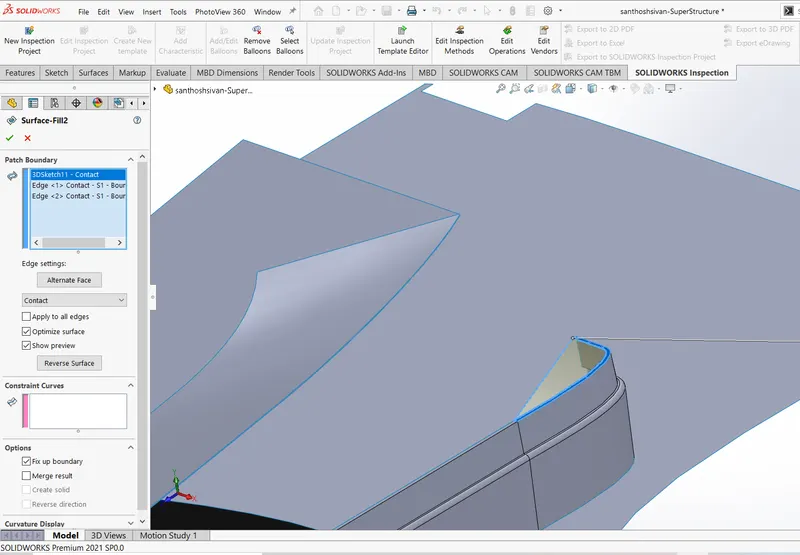
D.Surface fill:
Surface fill means to fill empty surface in the model. To create surface fill, click filled surface or select Insert-->Surface
-->Fill. In property manage set the option based on type of fill and click ok.
E.Surface Extend:
Surface extend means to merge the surface on another surface in this option used for trim and some other entity. To create surface, extend, click surface extend on feature or select insert-->Surface-->Extend. Select the edge and set value in property manager then click ok.
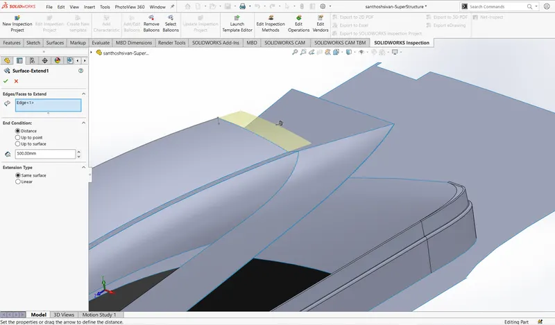
Superstructure model:
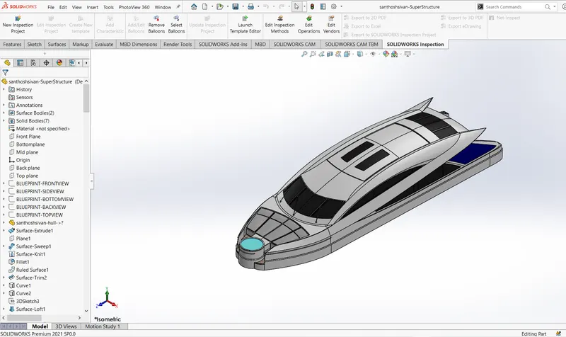
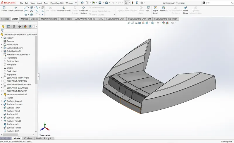
7.Front seat:
For creating front seat by using surface and solid features already discussed previously. In this mode we use dome option for realistic view.
Front seat model:
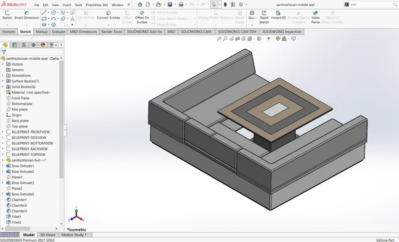
8.Middle seat:
Same features used for creating middle seat.
Middle seat Model:
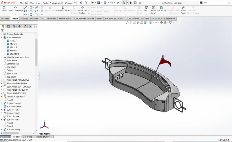
9.Rear seat:
For creating rear seat same solid and surface features used as same as front and middle seat.
Rear seat model:
10.Radar mast:
Solid features used to create radar mast.
Radar mast model:
Assembly of yacht tutorial:
Assembly is most important thing in solid works, because putting components together in an assembly line, but more specifically, it refers to creating a complete product that performs and intended function.
For most operation, the behavior of components is the same for both types. Adding a component to an assembly creates a link/mate between the assembly and the component.
When solidworks opens the assembly. It finds the component file to show it the assembly. In assembly they are two types of approaches as following below
1.Top-Down approach
2.Bottom-up approach
1.Top-down approach:
In top-down approach design, parts, shape and size and location can be designed in the assembly environment itself. You can use top-down design techniques on certain features of a part, complete parts, or entire assembly. The main advantage of top-down design is that much less rework is needed when design changes occur.
2.Bottom-up approach:
In bottom-up approach design is the traditional method. You will first design and model parts individually, then insert them into an assembly and use. If there is any interference in assembly or changes required in the assembly you need to modify the components individually either in the assembly level or part document level.
Yacht model:
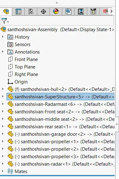
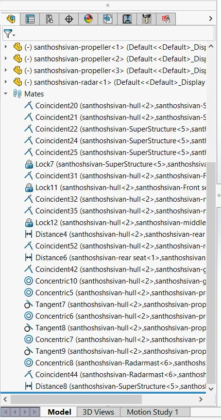
History tree:
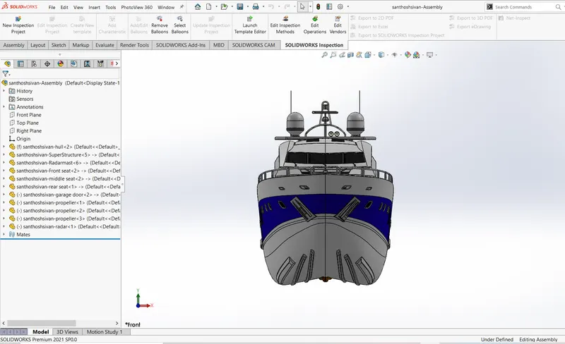
Front view:
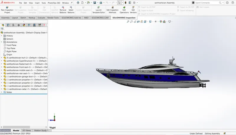
Right side view:
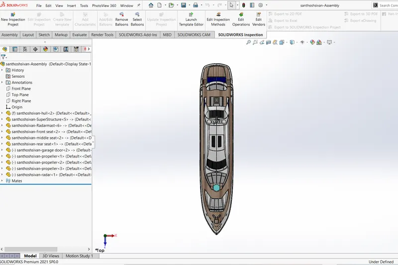
Top view:
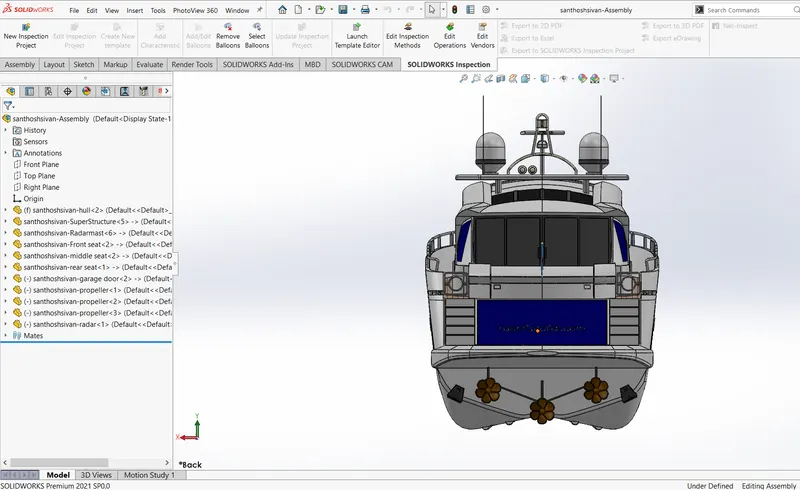
Back view:
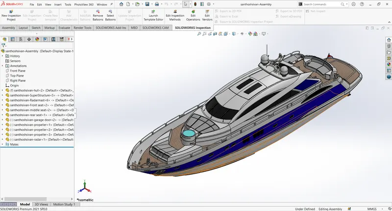
Isometric view:
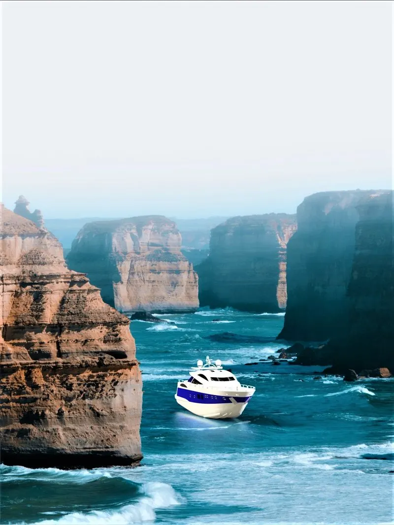
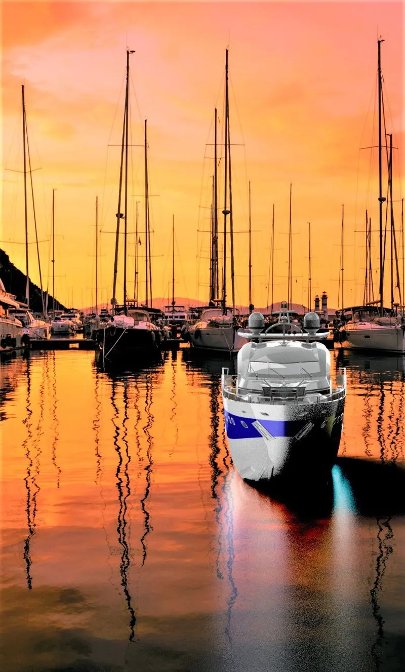
Rendering:
Rendering id another main thing in design because its give a realistic view for the component by giving using appearance and camera.
In solidworks photo view 360 is add-in that produces photo-realistic rendering of solidworks model. The rendered image incorporates the appearances, lighting, scene and decals include with the model. Photo view 360is available with solidworks professional or solidworks premium.
For photo view 360 click the photo view 360 option or click Tools-->Add-in and add in photo view 360.in that feature select preview option. New preview window is open and see how changes you make to model affect the rendering. Now edit appearance, scene and decals after completing all things, once again click preview option and see how those things works. Finally select final render in photo view 360.
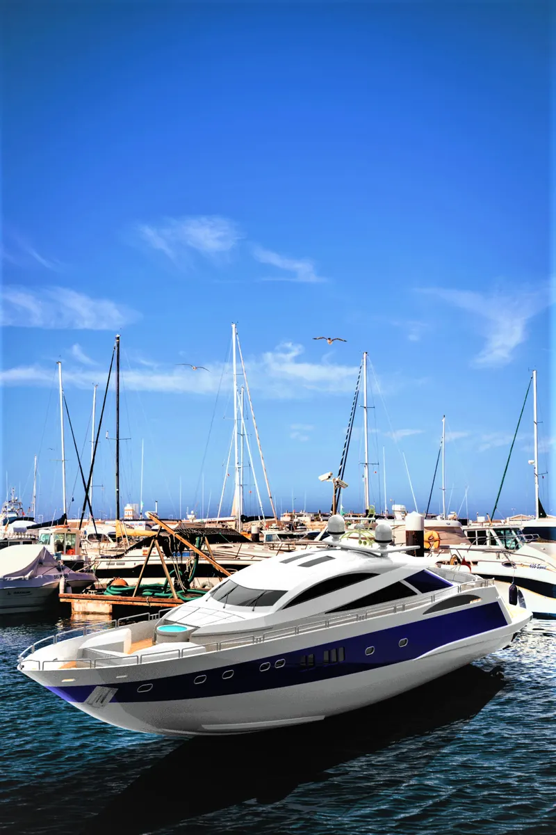
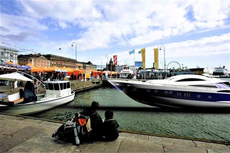
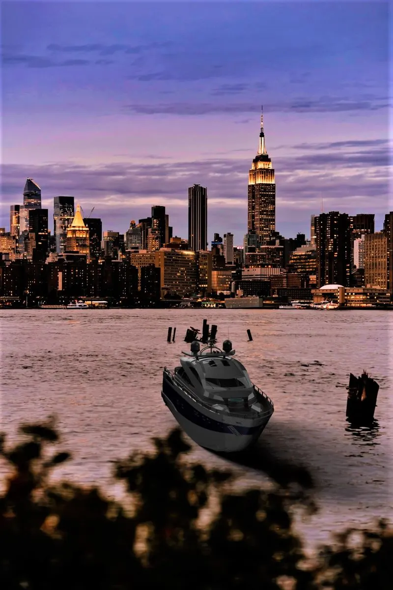
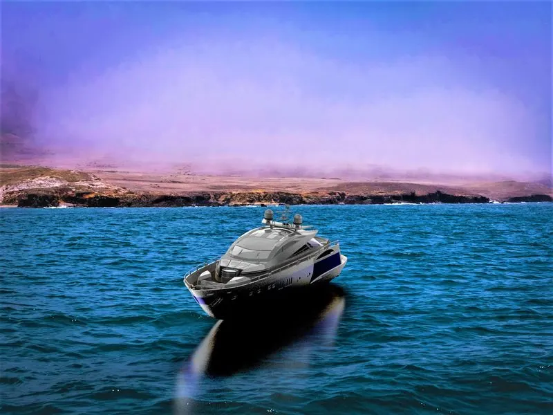
And also, you can make rendering in solidworks visualization. In solidworks visualize import the model and click snap to floor option after that import backplate and set some values, latitude, longitude and some other entities.
After modify the changes click render option, and select the desire folder. Then select render options and give passes value. Finally click ok.
Rendered Images:
Conclusion:
All components for yacht have successfully completed by using solidworks and here we can use HDR environment, appearance, scenes, backplate and finally rendered yacht by using solidworks visualize.
Yacht assembly
Front view
Right side view
isometric view
History tree
History tree 1