Roof Design
Aim:
To perform a curvature study on the given roof and develop necessary reinforcements such as front roof rail, rear roof rail, bow roofs, and center roof.
The Automobile Roof:
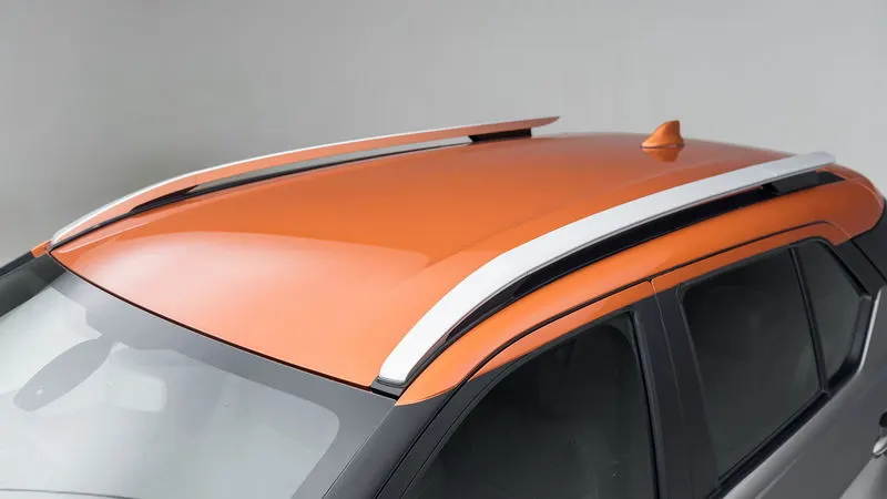
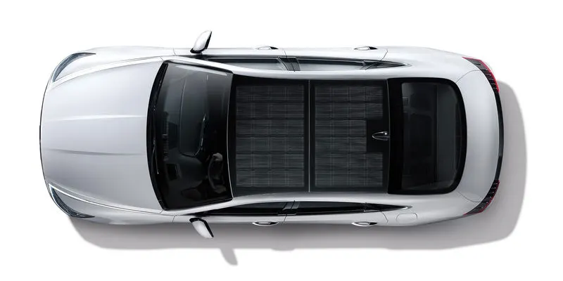
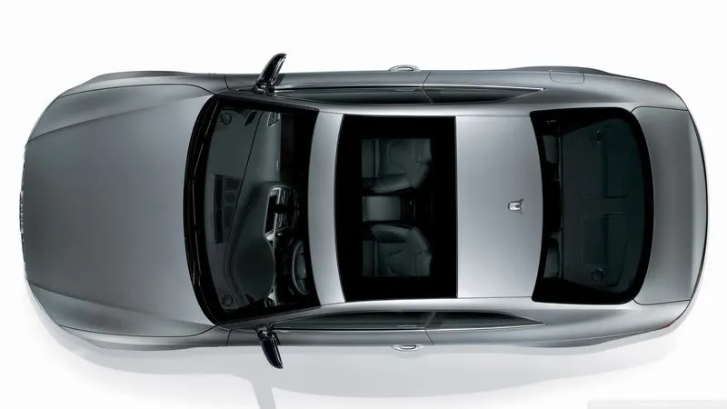
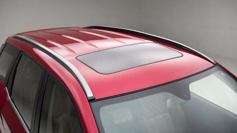
An automobile roof or car top is the portion of an automobile that sits above the passenger compartment, protecting the vehicle occupants from sun, wind, rain, snow and other external elements. There are various types of roofs.
Design Considerations for roof:
- Visibility Criteria
- Head Room Clearance
- Heat distortion and Snow Load Criteria
- Draft analysis for Manufacturability
Testing of Roof:
The actual strength of the roof is known only when a physical test is carried out on the roof. So, the roof is first designed with the above-mentioned considerations taken into account. Then it is manufactured and assembled with the car and it is tested and the strength is determined.
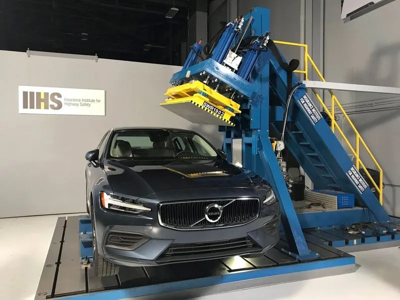
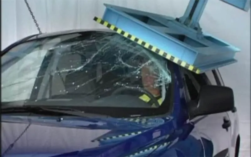
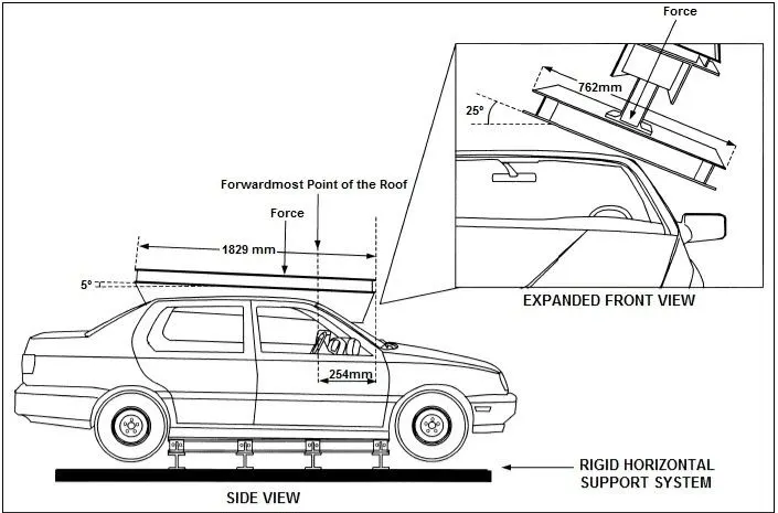
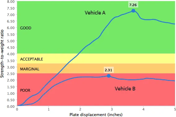
In the test, the strength of the roof is determined by pushing an angled metal plate down on one side of the roof at a slow but constant speed and measuring the force required to crush the roof. The force applied relative to the vehicle's weight is known as the strength-to-weight ratio. The peak strength-to-weight ratio recorded at any time before the roof is crushed 5 inches is the key measurement of roof strength.
A good rating requires a strength-to-weight ratio of at least 4. In other words, the roof must withstand a force of at least 4 times the vehicle's weight before the plate crushes the roof by 5 inches. For an acceptable rating, the minimum required strength-to-weight ratio is 3.25. For a marginal rating, it is 2.5. Anything lower than that is poor.
The Styling Surface Skin Data:
The skin data is given by the styling team. From the given data the styling surface and points are extracted and the design of reinforcements is carried.
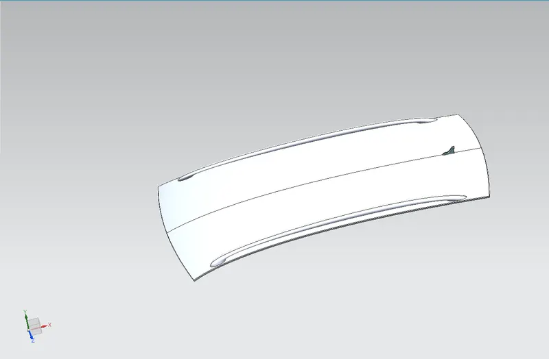
As the given surface is the styling surface of the overall outside roof, the outer panel is needed to be designed with all the necessary flanges to enable connecting the roof outer panel with the vehicles body.
Roof Outer Design:
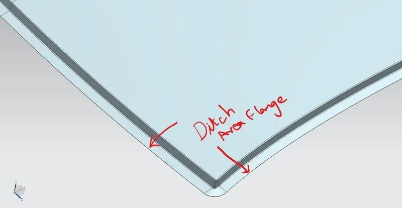
The roof outer panel is designed by extracting the styling surface from the given skin data. The flange creation dimensions and data are given in the master section provided. These flanges contribute to the ditch area which holds all the reinforcements in place with the help of spot welds.
Roof Reinforcements:
The reinforcements for the roof are
- Front Roof Rail
- Rear Roof Rail
- Bow Roof Rails
- Center Roof Rail
Front Roof Rail:
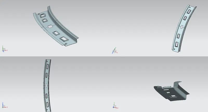
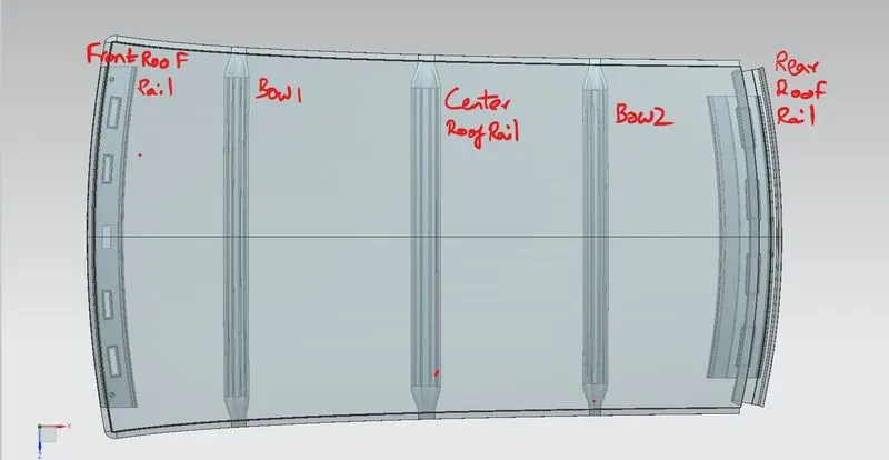
The Front Roof Rail is the reinforcement which is given to the front of the roof to withstand the load of the roof outer panel. It is designed in accordance to the master section reference. The front roof rail design should meet the visibility criteria, head impact criteria and head room clearance. It has the necessary mounts for front cabin lights, sun visors and sunglass holder. Embosses are given to increase the strength.
Rear Roof Rail:
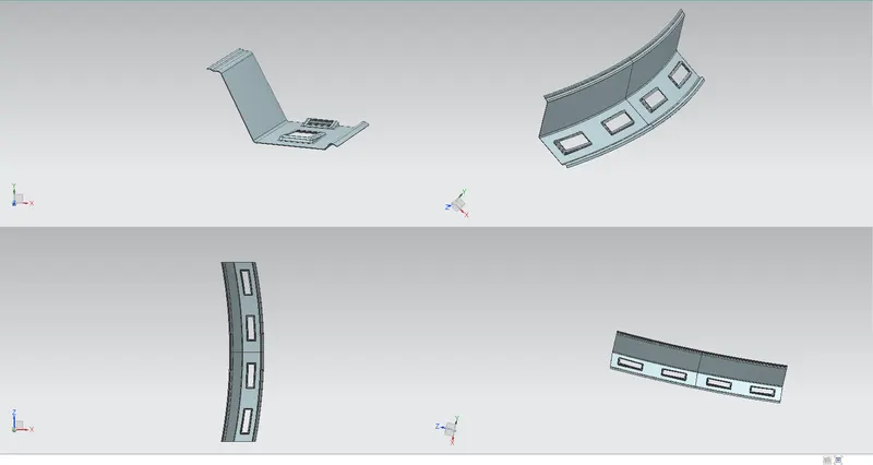
The Rear Roof Rail is the reinforcement given at the rear portion of the roof outer panel. It carries the hinge area for the back door/ tailgate. It is designed by following the master section reference. Embosses are given to increase the strength.
Bow Roof Rail:
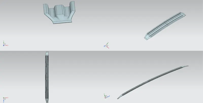
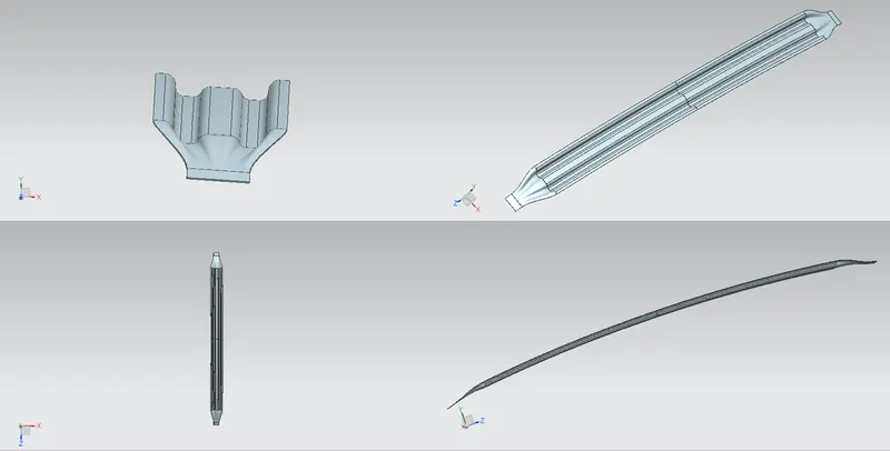
The Bow Roof Rail is the reinforcement which is given over the span of the roof to withstand the loads of the roof from external factors and to protect the shape of the roof from distortion and disruption. The number of bow roof is varied with the length of the outer roof panel.
Center Roof Rail:
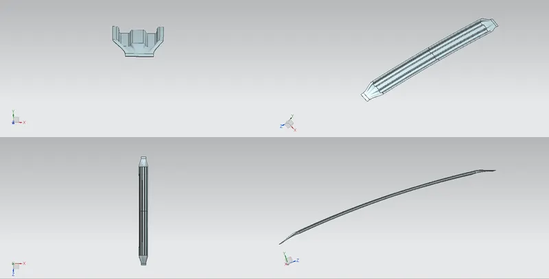
The Center Roof Rail is the reinforcement that is given in the exact center point of the roof. It carries the load in the center and it has the necessary mounts for the cabin lights and the a/c vents in some cars. It is designed by following the master section reference.
Mastic Sealants:
All the reinforcements are joined with the help of spot welding at the flange area and with the help of mastics in between the panels and reinforcements. So, in all reinforcements a 5mm gap is provided between the inner and outer panels to introduce the mastics.
Completed Roof Design:
Draft Analysis:
As all the parts are deep drawn it should have a positive draft so that the tool is not damaged and enabling the ease of manufacturing. The minimum draft angle is 7°. Hence the bow roofs and the center roof are analysed for the positive draft.
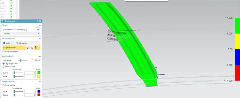
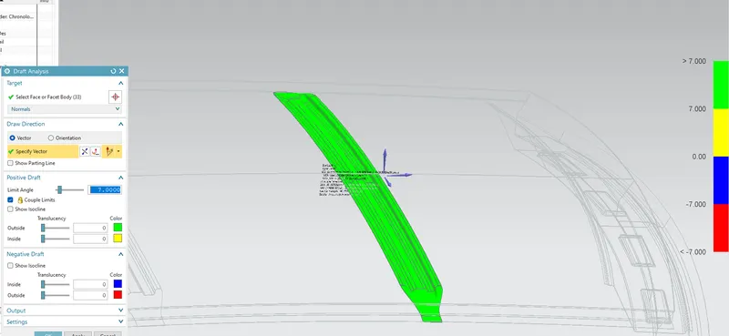
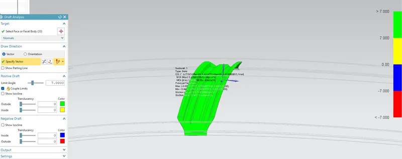
With these results it is evident that all the parts have a positive draft so it will be easy to manufacture.
Curvature Study:
The position of the bow roofs are determined by the curvature study of the roof outer panel’s curvature and the reinforcements in place.
The roof’s curvature is determined by two criteria
- Heat distortion criteria
- Snow load criteria
But in order to find out these criteria the bow roofs are tentatively positioned and the study carried out.
Heat Distortion Criteria:
`W=[1.73×〖10〗^(-3)×L]+[1.85×〖10〗^(-8)×R^2/t]+[1.10×〖10〗^(-3)×l]-2.68`
Where
L – Roof Length in X-Direction at 0Y
R – Roof Curvature, `R=2 ((R_x×R_y))/((R_x+R_y))`
Rx – X-Curvature
Ry – Y-Curvature
t – Plate Thickness of Roof
l – Bow Roof Span
The judgement condition,
- If the value of W is less than 2.7, then the positions are correct. i.e., W<2.7.
- If the value of W is between 2.7 and 3.5 then the outer panel is required of reinforcements like ridges and embosses to increase the roof strength and to suffice the heat distortion criteria. i.e., 2.7≤W<3.5.
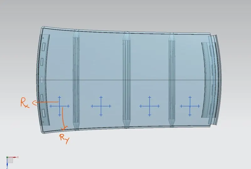
After getting all the values and applying in the formula for different sections of the roof, and the results are found out as follows.

As the result is seen, the value of W at all sections are within the judgment condition. And hence the roof design is passed in the heat distortion criterion.
Snow Load Criteria:
`Q_r=([I_y×t^2])/[α×s×[[R_x+R_y ]/2]^2×〖10〗^(-8) ]`
Where
`α= M_y×〖L_x〗^2×10^(-12)`
`M_y=Y (L_y-Y)`
t – Roof Plate Thickness
Ly – Distance between Front and Rear Rails in 0Y
Lx – Distance between the extreme ends of the roof on the roof bow
Y – Distance between the Front Roof Rail to the Bow Roofs
s – Distance of the roof rails bearing the distributed load
`s=[L_1/2]+[L_2/2]`
Iy – Geometrical moment of inertia of the bow roof (Y-Cross Section)
Rx – X-curvature
Ry – Y-curvature
The judgement condition,
The value of Qr is greater than or equal to 3.1. i.e., Qr≥3.1. 250≥ s ≥380.
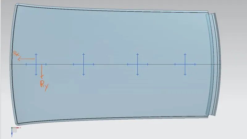
After getting all values and applying in the formula for different sections of the roof, and the results are found out as follows.

As the result is seen, the value of ’Qr’ at all sections are within the judgment condition. And hence the design is passed in the snow load criteria.
Section Inertia Analysis:
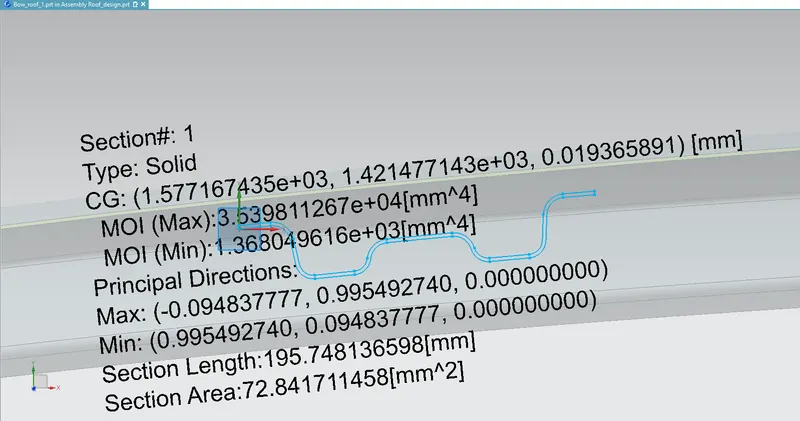
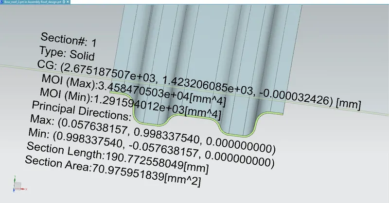
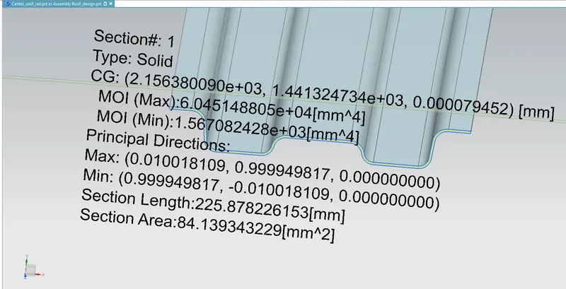
The moments of inertia are carried out by the section inertia analysis tool in the analysis tab. The existing section method is selected and the curves are selected from each section of the bow roofs and center roof and the type of section is selected as solid and the moment of inertia is calculated.
Errors/Problems Faced During Design:
- Had problems in creating emboss in rear roof rail
- Problem while thickening the bow roof near the front roof rail
- Result of snow load criteria at the bow roof 2 section failed due to the L2 value in the shared load distance
Measures Taken to Rectify:
- Found that an open sketch creates the problem in embossing and corrected by closing all the open geometries
- Selected the ‘improve gash’ checkbox in the thicken command and changed the tolerance value
- positioned the bow roof 2 near the rear roof rail so that it suffices the criteria(not reflected in the model)
Conclusion:
The design of the roof is completed and all the necessary flanges and reinforcements are created with the given skin data and by following the master section references.