Roof Design
OBJECTIVE
To design a car roof with all its components assembled using NX-CAD tool in reference to given master section for design parameters and considerations. Roof components include front roof rail, bow roof rails, centre roof rail and rear roof rail. Heat distortion and snow load criteria and section modulus of the designed roof need to be performed. A draft analysis is to be analysed to meet proper manufacturing procedure.
INTRODUCTION
A car roof is considered an essential component of BIW design. The roof shields the passengers of the vehicle from the sun, wind, rain, and other external elements. Roof rails are used to reinforce the outer panel and to support other items in a vehicle. Basically, roof also provides an aerodynamic support to the car while in motion.
Types of car roof present are:
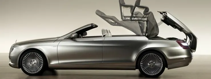
- Convertible roofs
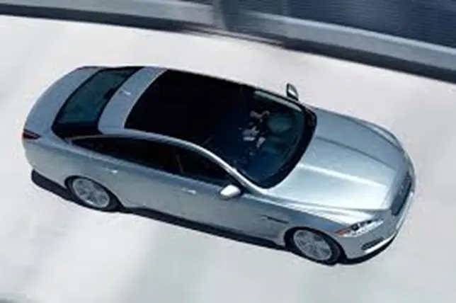
- Sunroofs
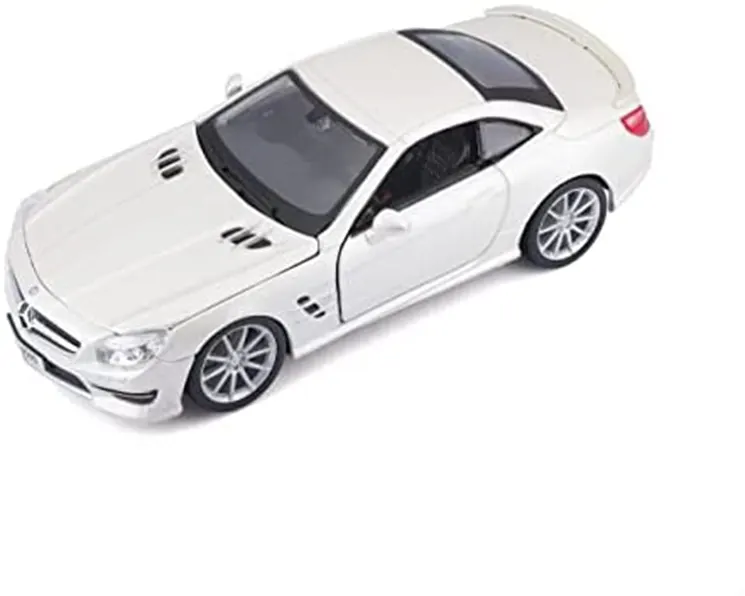
- Hardtops
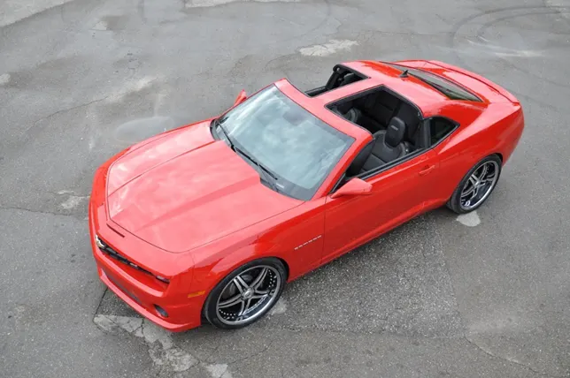
- Vinyl roofs

- Targa tops

- T-tops
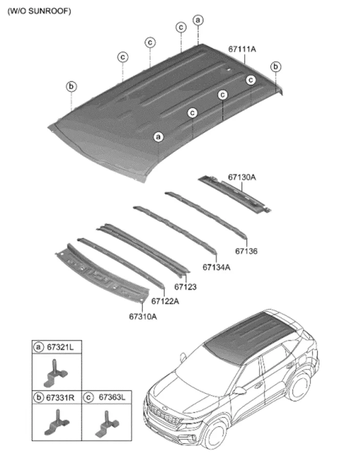
Roof of a car basically consists of:
- Front roof rail panel
- Bow roof rail panels
- Centre roof rail panel and
- Rear roof rail panel
Design considerations for roof design are:
- Draft analysis
- Head clearance for comfort
- Visibility criteria
- Heat distortion and Snow Load
- Safety Parameters
Roof Crash Test Procedure
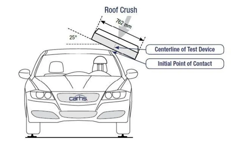
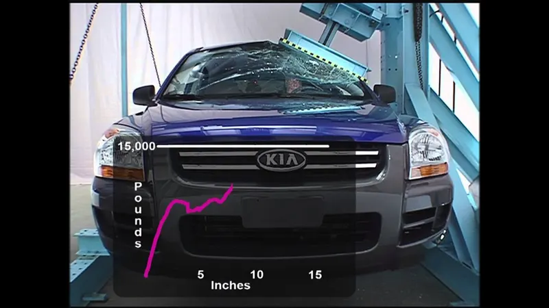
The vehicle or body-in-white is mounted on the rig bedplate and supported along the sills and chassis frame to perform a roof crush test. The loading platen is lowered onto the roof structure while being held at the required angles by the regulations. The vehicle is then loaded to the specified force based on the unloaded mass of the car.
Prior to each test, force and displacement data are recorded for 5 seconds while the test system holds the loading platen at initial roof contact. The data collected between 1 and 4 seconds of this hold time are averaged for each channel to produce a measurement offset that is subtracted from the data collected during the roof crushing. The force-displacement curve is plotted using the summed output from the five load cells and the average displacement from the four LVDTs after the offset for each channel is removed.
During the roof crush test, video recordings from inside and outside the vehicle are made for post-test analysis of the roof structure performance. A post-test investigation of the vehicle's structural performance is carried out with or on behalf of the customer and is documented with photographs.
DESIGN METHODOLOGY
Roof Design Using NX-CAD
Using the master sections provided the design of roof with all reinforcements are to be created using NX-CAD tool considering all factors affecting the roof design, manufacturing and life.
While designing the panel the following are to be considered:
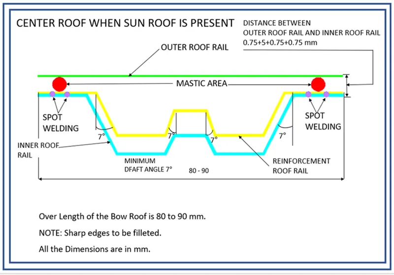
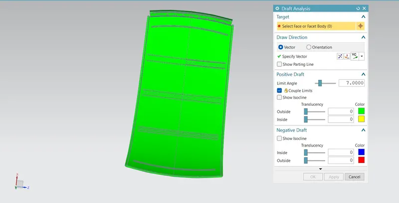
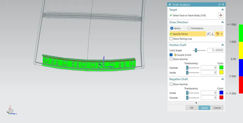
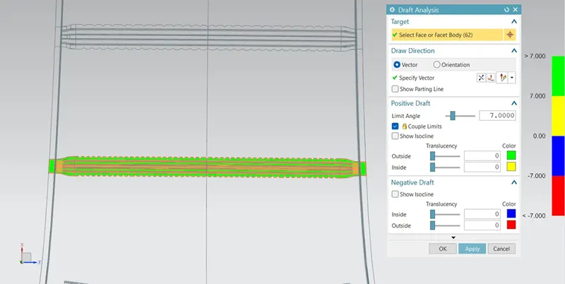
- All faces must have a minimum draft of 7 degrees.
- All sheet metal parts have a thickness of 0.75 mm.
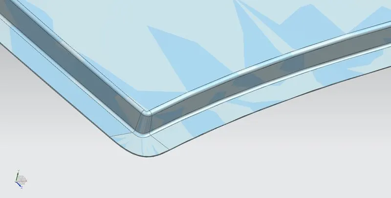
- There should be no sharp edges and all edges should have fillets.
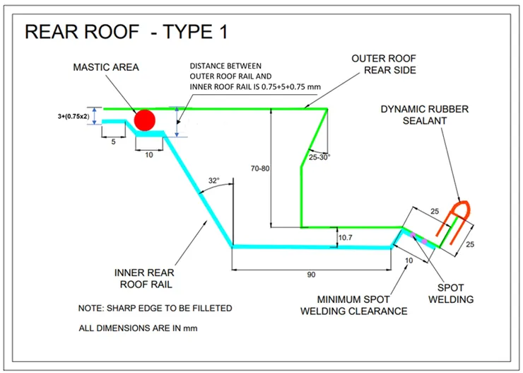
- There should be a 5 mm clearance between the outer roof rail and the front roof rail, rear roof rail, bow roof, and reinforcement centre where mastics are used for adhesion.
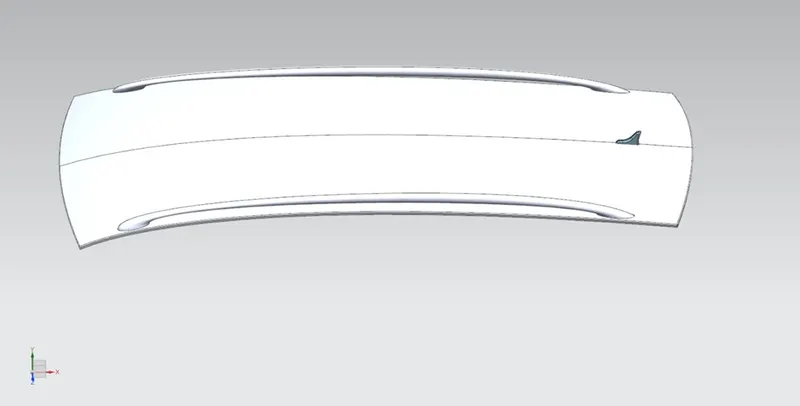
Front Roof Rail
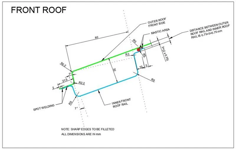
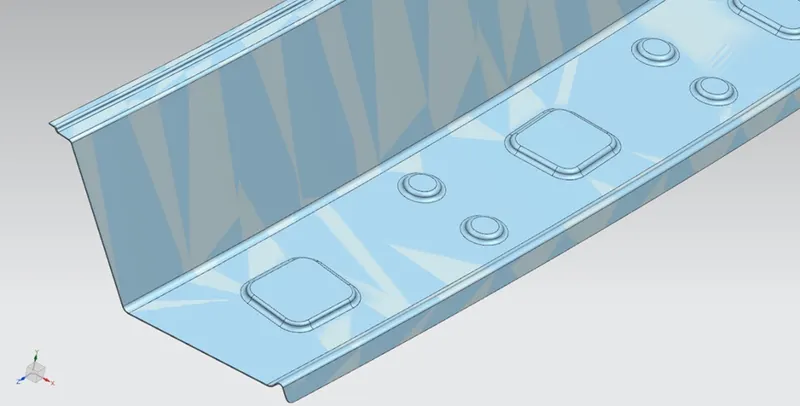
Using the master section provided the front roof rail is designed as below
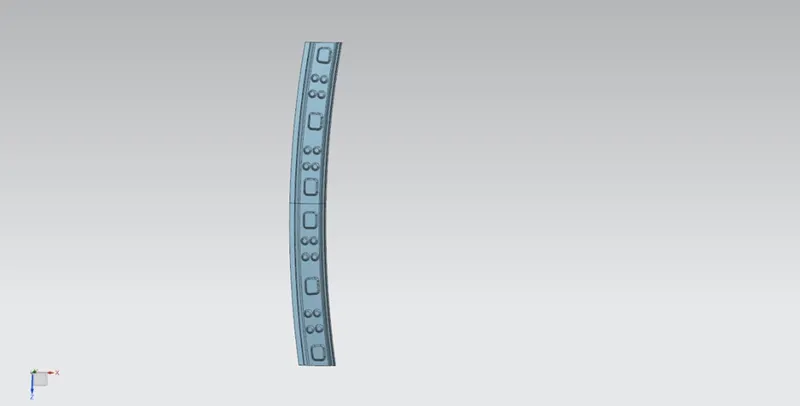
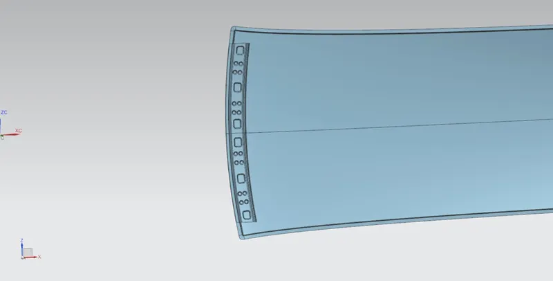
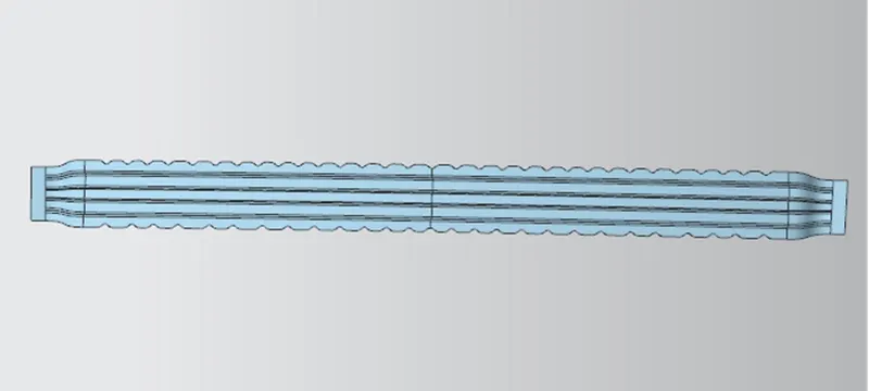
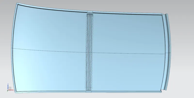
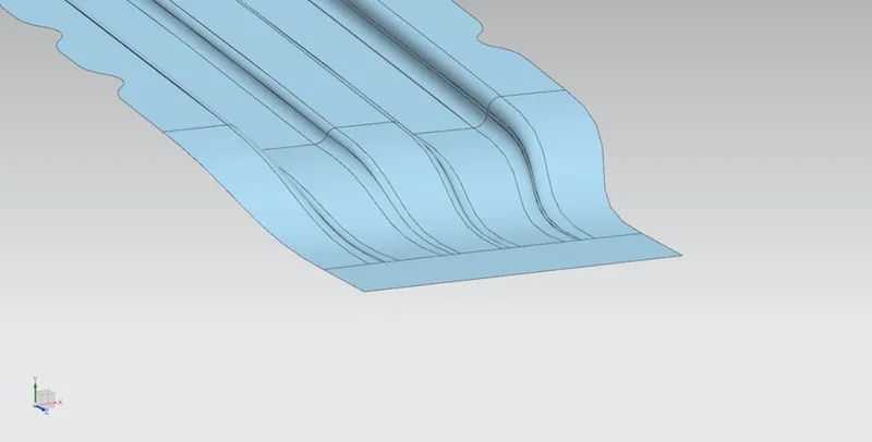
Embosses are created for strengthening the panel.
Centre Roof Rail
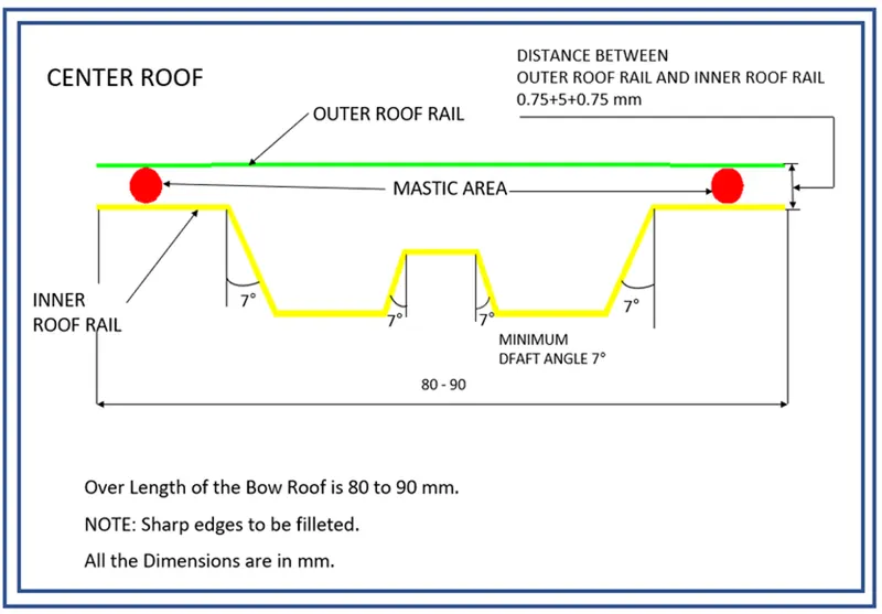
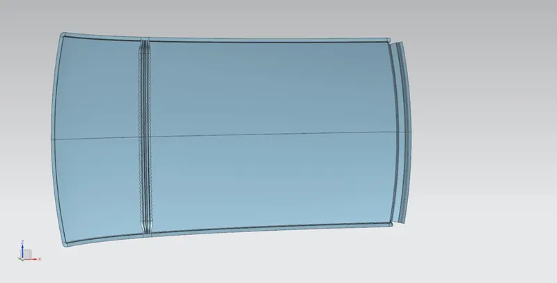
Centre roof rails are mostly located in the centre of the roof along the entire part.
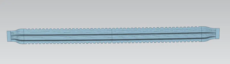
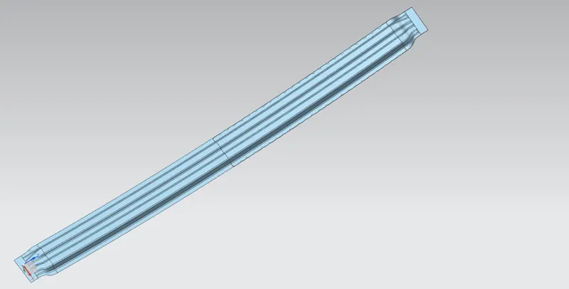
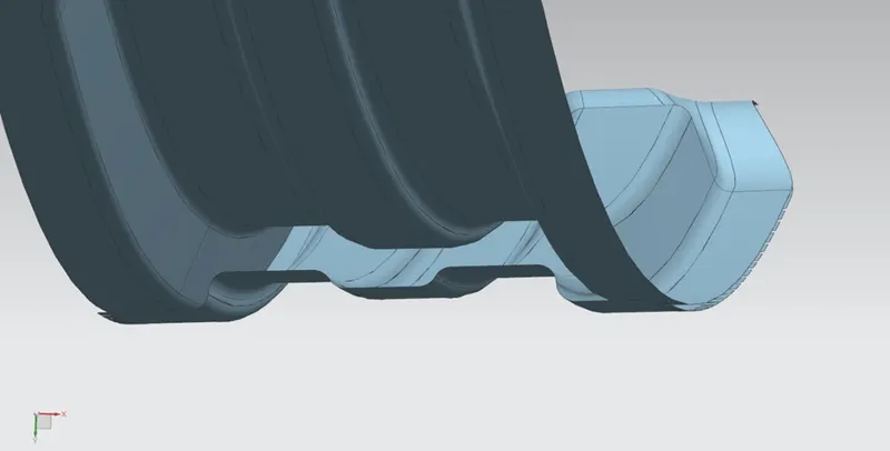
Bow Roof Rail
Centre Roof When Sunroof is Present
Rear Roof Rail
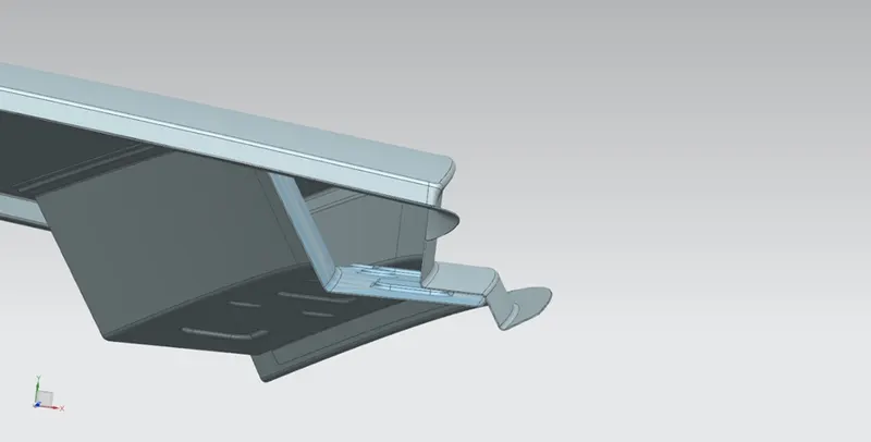
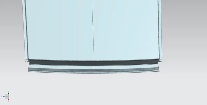
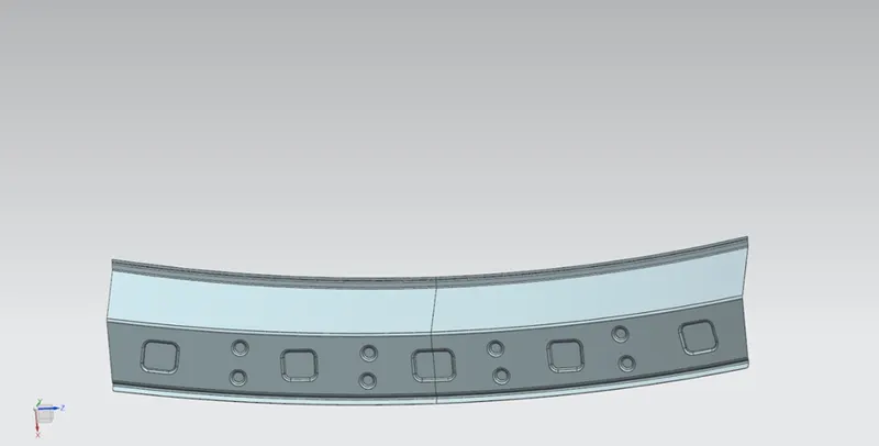
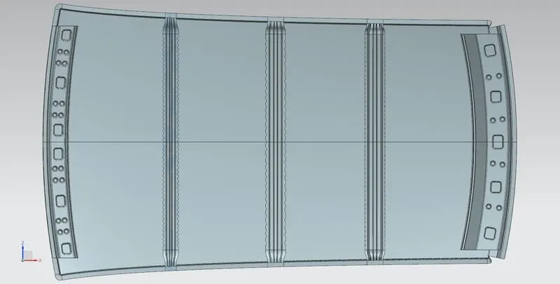
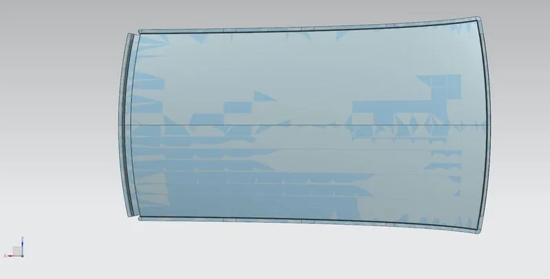
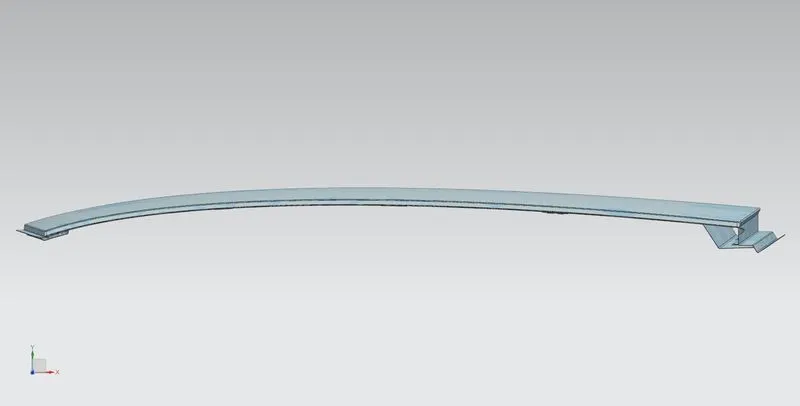
Roof Designed
DRAFT ANALYSIS
Draft analysis of 7 degrees is performed to analyse the draft angle for manufacturing feasibility.
Front Roof Rail
Bow Roof Rail
Centre Roof Rail
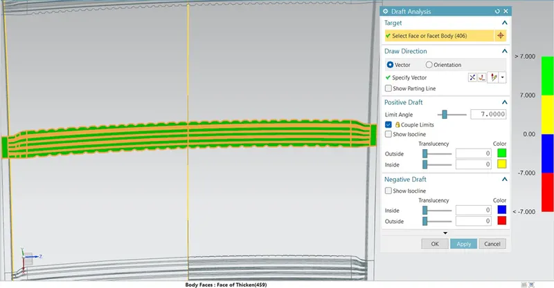
Bow roof rail 2
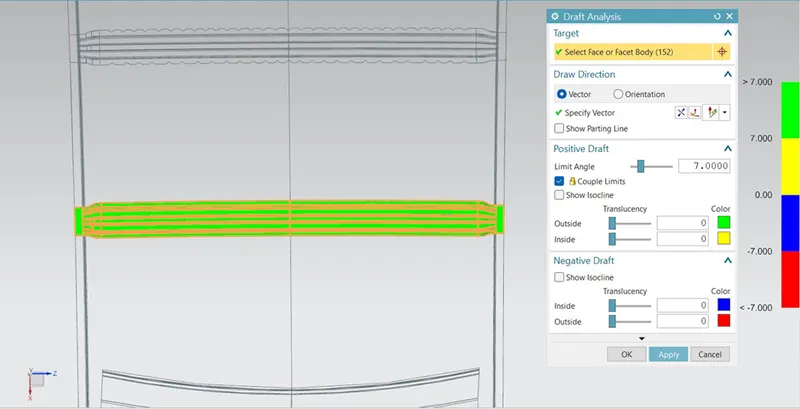
Rear Roof Rail
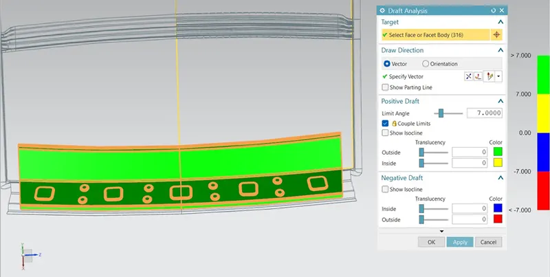
Heat Distortion Study
The study of heat distortion on roof plays a major role in sheet metal and design consideration parameters. Bending of roof or damages caused due to increased temperature on surface of roof is to be studied carefully using heat distortion formula and optimization of the panel and reinforcements are done thereby increasing strength.
Bow–Roof Prediction Formula
W = [1.73 x 10^(-3) x L] + [1.85 x 10^(-8) x (R^2)/t] + [ 1.10x10^(-3) x l] - 2.68
Where,
L = Roof Length in X-Direction[mm](Roof dimension in 0-Y)
R = Roof curvature
R = 2(Rx*Ry)/(Rx+Ry)
Rx = X curvature
Ry = Y curvature
t = Roof plate thickness [mm]
l = Bow Roof Span [mm]
Judgment Condition
OK< 2.7>3.1
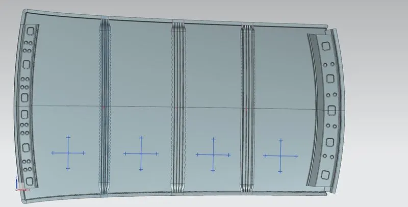
Here, we must determine the RX and Ry values.
- Create a sketch of the top roof and draw a horizontal line through the center.
- Then offset this line below 300mm and called it as -3Y line.
- Offset 100 mm above and below the -3Y line and convert all of these lines to reference lines.
- Draw vertical lines in the center of each reinforcement and offset them by 100 mm on both sides.
- Intersection point is created for the lines.
- Project these points to the outer roof panel.
- Three point arches are made to determine the deflection radius on these points
Calculations
|
Roof Rail |
Ry |
Rx |
R |
I |
L |
t |
R2/t |
W |
Remark |
|
Front-Bow Roof Rail 1 |
5766.1737 mm |
1908.1307 mm |
2867 |
482 |
2123.5070 |
0.75 |
10959585 |
1.72 |
OK |
|
Bow Roof Rail 1-Centre |
4529.1890 mm |
6385.4115 mm |
5299 |
474 |
2123.5070 |
0.75 |
37439201 |
2.21 |
OK |
|
Centre Rail- Bow Rail 2 |
3094.6177 mm |
4054.6220 mm |
3510 |
444 |
2123.5070 |
0.75 |
16426800 |
1.77 |
OK |
|
Bow Rail 2- Rear rail |
4517.3525 mm |
14176.9465 mm |
6851 |
533 |
2123.5070 |
0.75 |
62581601 |
2.7 |
OK |
From the above table and calculation it can be concluded that all values of W is under 2.7 and also not greater than 3.1, thus it reinforced locations for bow roofs pass the heat distortion test.
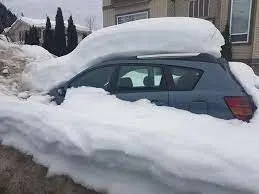
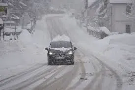
Snow Load Condition
Snow Load Prediction Formula
Qr = [Iy x t2] / [α x s x [(Rx + Ry)/2]2 x 10-8]
Note: The Qr value given over here is correct. There was a typo error in the formula given in the video.
Where,
α = My x Lx2 x 10-12 , My = Y(Ly-Y)
t = Roof plate thickness [mm]
Ly = Distance between the front and rear roof Rails on the Vehicle along with 0Y[mm]
Length of Roof panel with the centre point between Roof rail Front /Rear as the front and rear reference point.
Lx = Distance between the Left and Right end of the roof on the Roof BOW [mm]
The width of the roof panel is exposed on the surface.
Y = Distance front roof rail to roof bOW[mm]
s = Distance for which Roof BOW bears divided load [mm]
s = L1/2 + L2/2
Iy = Geometrical moment of inertia of Roof BOW (Y cross-section)[mm4]
Rx = Lateral direction curvature radius of roof panel Y cross-section on Roof BOW [mm]
Roof panel curvature Radius of the Length Lx in Front view
Ry = Longitudinal Direction curvature radius of the Roof panel X cross-section on Roof BOW [mm]
Roof panel X curvature radius of length s in side view
Judgment condition
Qr ≥ 3.1
250 ≤ s ≤ 380
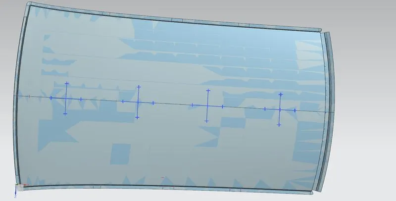
Here, we must determine the Rx and Ry values.
- Create a sketch of the top roof and draw a horizontal line through the center.
- Then offset this line below 100mm and called it as -Y line.
- Offset 100 mm above and below the -Y line and convert all of these lines to reference lines.
- Draw vertical lines in the center of each reinforcement and offset them by 100 mm on both sides.
- Intersection point is created for the lines.
- Project these points to the outer roof panel.
- Three point arches are made to determine the deflection radius on these points
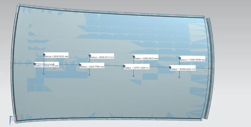
Calculations
|
Roof Rail |
Rx |
Ry |
Lx |
Ly |
Y |
α |
Iy |
s |
t |
Qr |
Remarks |
|
Front-Bow Roof Rail 1 |
2640.558 |
2748.2773 |
1115.4745 |
2095.7187 |
427.5192 |
0.938544183 |
1049.89 |
479.74775 |
0.75 |
18 |
OK |
|
Bow Roof Rail 1-Centre |
2938.2311 |
6322.7766 |
1080.5609 |
2095.7187 |
400.5722 |
0.886873756 |
1744.47 |
459.53025 |
0.75 |
11 |
OK |
|
Centre Rail- Bow Rail 2 |
6250.862 |
10770.1299 |
1061.8525 |
2095.7187 |
359.7043 |
0.830601972 |
3965.82 |
501.1179 |
0.75 |
8 |
OK |
|
Bow Rail 2- Rear rail |
10381.6258 |
16282.2434 |
2095.7187 |
392.8748 |
6253.86 |
272.28715 |
0.75 |
- |
The bow roofs reinforced to the roof thus pass snow load test as Qr lies as ≥ 3.1.
Section Modulus
Section modulus is a geometric property for a given cross-section that is used in the design of beams and flexural members. A beam or flexural member will be stronger and capable of supporting greater load if it has a higher section modulus than the other. It is defined as the ratio of the moment of inertia of a section about its centroidal axis and to the distance of the extreme end from the neutral axis. The unit of section modulus is mm³.
Where,
- S = section modulus (mm3)
- I = moment of inertia (mm⁴)
- y = distance from neutral axis to extreme end (mm)
Front Roof Rail
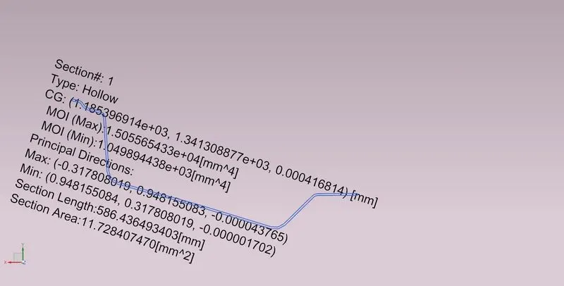
Moment of Inertia (max)=1.505565×104 mm4
Moment of Inertia (min)=1.04989×103 mm4
Bow Roof Rail
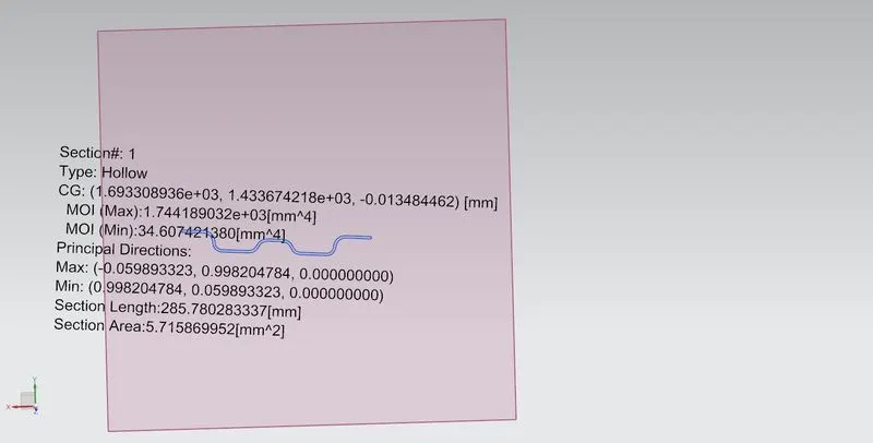
Moment of Inertia(max)= 1.744189×103 mm4
Centre Roof Rail
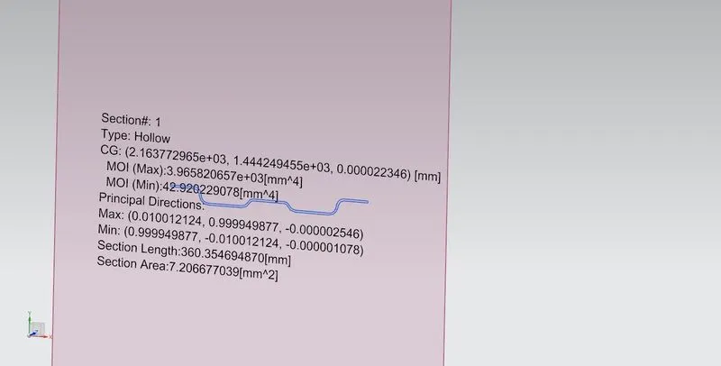
Moment of Inertia(max)= 3.9658×103 mm4
Bow roof 2
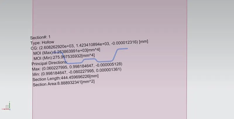
Moment of Inertia(max)= 6.25386×103 mm4
Rear Roof Rail
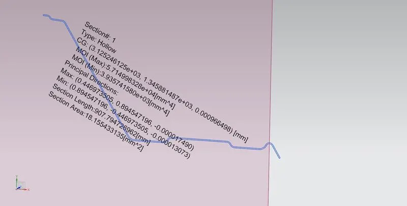
Moment of Inertia(min)= 3.93574×103 mm4
CONCLUSION
The roof, front roof rail, bow roof rails, centre roof rail and rear roof rails are successfully designed meeting all the design and safety factors. Heat distortion test, snow load test, section modulus of each reinforcements and draft analysis for each components were performed meeting all the limits specified.