Roof Design
Aim:
To design a Car Roof and to do the curvature study to resist Heat distortion and snow load condition of the same.
Intraduction:
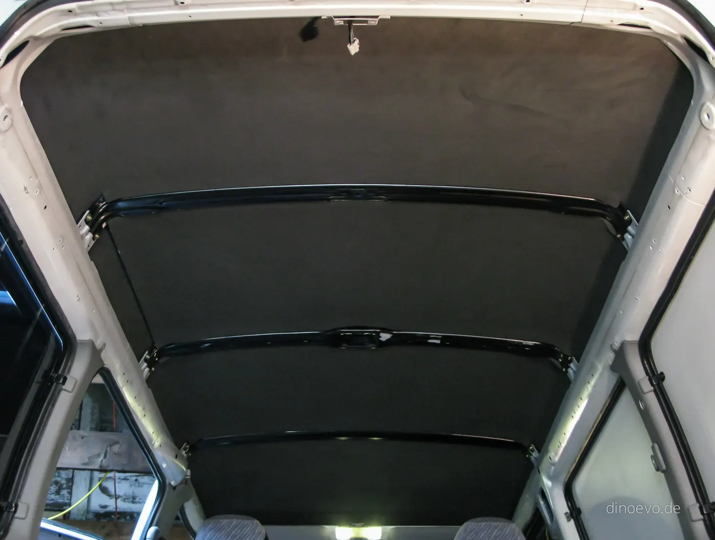
Roof is not just a styling surface, it provides protection to the vehicle occupants so we need a good structure to the roof. In the roof assembly we have roof rail, roof bow, roof support etc which make the roof stronger.
As a safety point of view roof panel is undergone through varies test in which crush test and roll over test look for the strength of the part. So when designing we have to consider strength as an important point.
Types of Automobile roof:
- Convertible:A convertible ,cabriolet or spyder is a passenger car that can be driven with or without a roof in place.
- Hardtop:A hardtop is a rigid form of automobile roof,which for modern cars typically constructed from metal.A hardtop roof can be either fixed,detachable for separate storing or retractable within the vehicle itself.
- Sunroof:An Automotive sunroof is a movable panel that is operable to uncover a window in an automobile roof.which allows light and fresh air into the passanger compartment.
- T-top: A T-top is an automobile roof with a removable panel on each side of a rigid bar running from the center of one structural bar between pillars to the center of the next structural bar. The panels of a traditional T-top are usually made of auto grade safety glass.
- Targa Top: Itis a semi-convertible car body style with a removable roof section and a full width roll bar behind the seats.
- Vinyl roof:Vinyl roof refers to a vinyl converting for a automobile’s top.This converting was orginally designed to give the appearance of a convertible to models with a fixed roof but eventually,it evolved into styling statement in its own right.
Design Consideration
Roof
An automobile roof or car top is the portion of an automobile that sits above the passenger compartment, protecting the vehicle occupants from sun, wind, rain, and other external elements. Becuase the earliest automoblies were designed in an era of horse-down carriages, early automobile roofs used similar materials and designs.
Front Roof Rail:
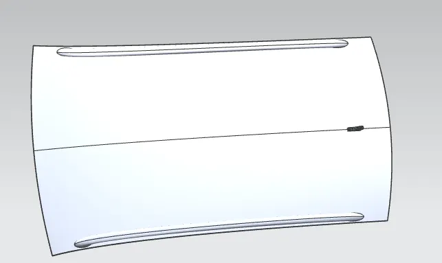
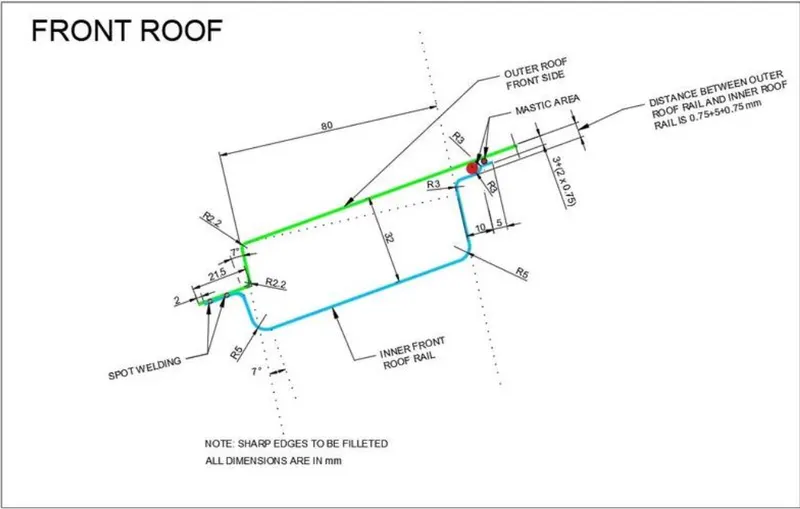
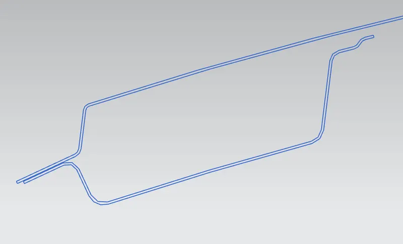
Front roof rails are used in the assembly of a roof in which it provide mounting provisions to windshield glasses and the changes in the front roof rail influences the frontal visibility of the passenger. The major design factor considered is the headroom clearance. The front roof rail also provides provision for the mounting the inside rear view mirror.
Master Section
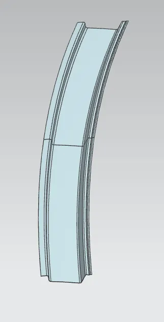
REAR ROOF RAIL:
The rear roof rail is the one of the important components of roof assembly which is used for the back door mounting. Similarly to front roof rail important design consideration includes rear passenger head clearance rear visibility of the vehicle.
Master Section
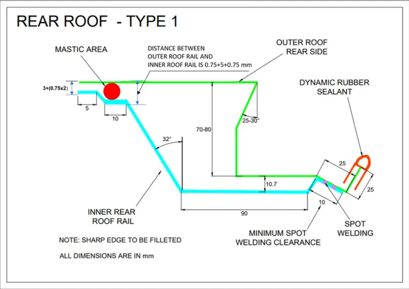
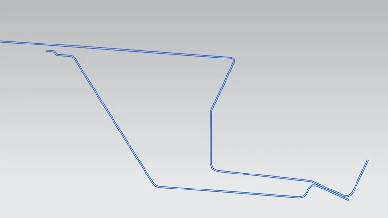
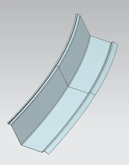
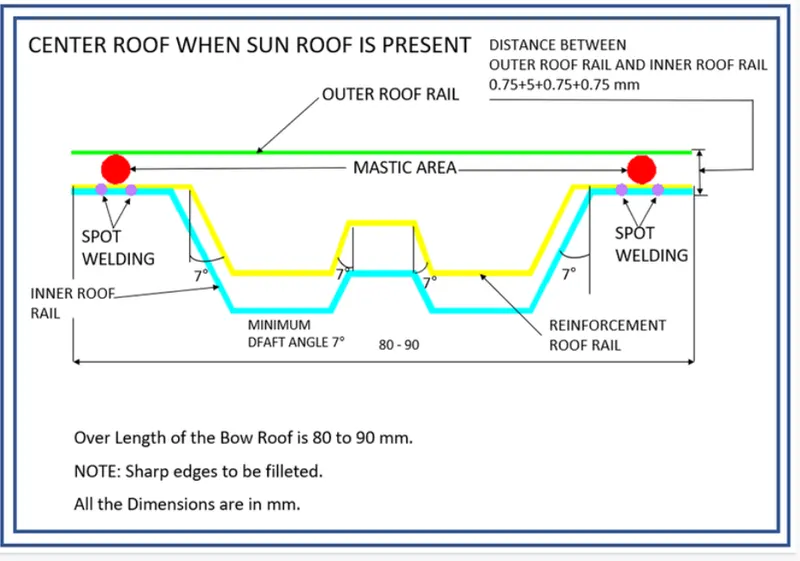
CENTER ROOF RAIL (REINFORCEMENT CENTER):
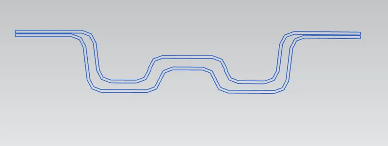
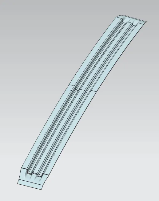
The reinforcement center is used as a cross member between bodyside LH and RH respectively. In some cases, the reinforcement center is not joined with the roof in both roof and bodyside. The reinforcement center and bow roof are joined either spot weld or by mastic sealants and provision for the same are given.
Master Section
BOW ROOF:
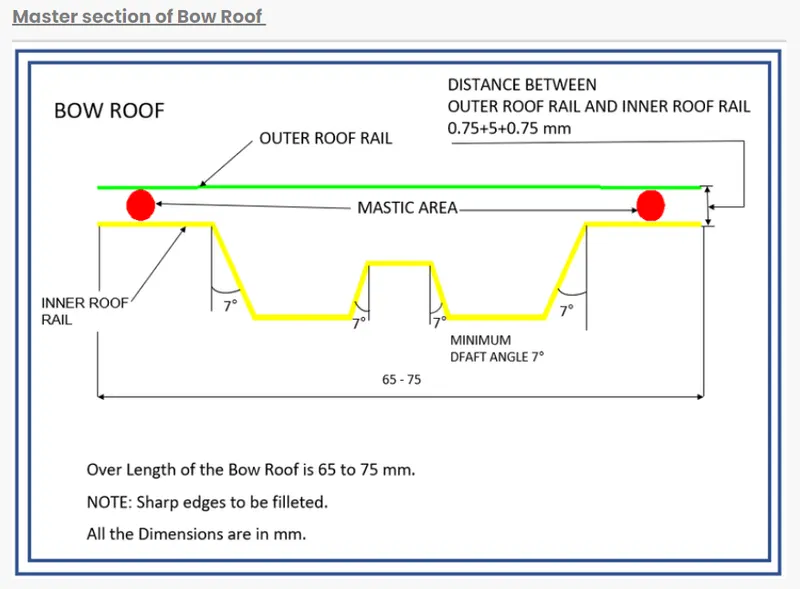
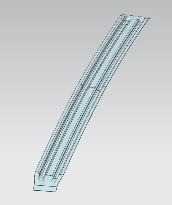
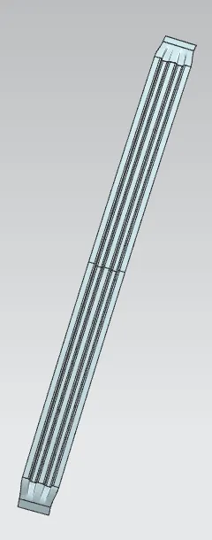
It is an additional stiffening member used in the roof assembly for the localized strength improvements and it is joined directly to roof itself with several spot welding or even with the mastic sealant.
Master section
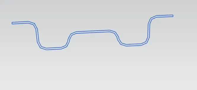
Bow 1&2
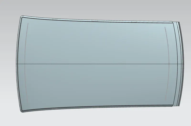
Outer Roof Panel
Heat Distortion Criteria:
In this critera, we check the heat distortion capacity of the roof at higher temperatures with the fixed load on it. So when the surrounding temperature is high and the roof is loaded with some weight on it then if the roof is deformed it fails, so to calculate whether the roof deform or not, according to the bow we do these calculatins as follows
Bow–Roof Prediction Formula
W = [1.73 x 10^(-3) x L] + [1.85 x 10^(-8) x (R^2)/t] + [ 1.10x10^(-3) x l] - 2.68
Where,
L = Roof Length in X-Direction[mm](Roof dimension in 0-Y)
R = Roof curvature
R = 2(Rx*Ry)/(Rx+Ry)
Rx = X curvature
Ry = Y curvature
t = Roof plate thickness [mm]
l = Bow Roof Span [mm]
Judgment Condition
OK< 2.7
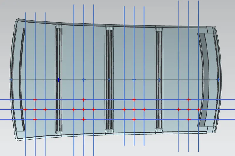
Steps to calculate the Heat distortions as follows:
1.First we offset the center y-axis line to 300mm distance apart from it represented as (-3Y to 3Y red line).
2.After that we offset this -3Y to 3Y to 100mm offset each side.
3.We draw the vertical line at the center of the two consecutive bow rood span. Next, we offset this red line to 100 on each side.
4. Now we have three horizontal lines and three 12 vertical lines we take the intersection points of the vertical line with three horizontal lines and a horizontal line we take the intersection of the vertical lines with that line.
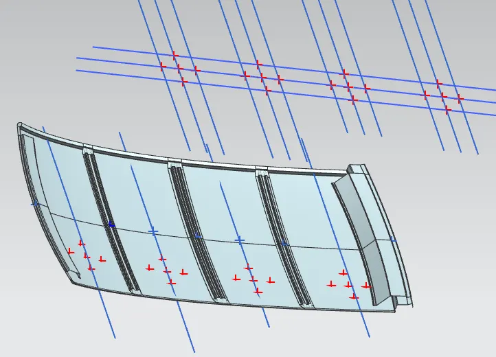
5.After getting all the points we project these points on the roof surface and draw the three points curve along the x-axis point to get the radius of curvature of Ry and along y-axis points to get the radius of curvature of Rx.
Calculation:
Front Roof Rail and Bow Roof 1
Rx= 2169.85
Ry= 5727.17
R = Roof curvature
R = 2(Rx*Ry)/(Rx+Ry)
R = 3147.17
I= 474.2
L= 2032.5
t= 0.75
Put all values in equation
W = [1.73 x 10^(-3) x L] + [1.85 x 10^(-8) x (R^2)/t] + [ 1.10x10^(-3) x l] - 2.68
W = 1.601
Condition is W>2.7, so position of Bow Roof 1 is Correct.
Result Table:
|
S.no |
Bow’s |
Rx |
Ry |
R |
I |
L |
t |
R2/t |
L1 |
L2 |
L3 |
W |
OK/NG |
|
1 |
FT & 1st |
2169.85 |
5727.17 |
3147.22 |
474.2 |
2032.5 |
0.75 |
13206658.304 |
3.516 |
0.244 |
0.521 |
1.601 |
OK |
|
2 |
1st & CR |
5908.86 |
5043.73 |
5442.12 |
504.62 |
2032.5 |
0.75 |
39488995.045 |
3.516 |
0.73 |
0.55 |
2.116 |
OK |
|
3 |
CR & 2nd |
10213.69 |
4050.27 |
5800.38 |
504.62 |
2032.5 |
0.75 |
44859210.859 |
3.516 |
0.82 |
0.55 |
2.206 |
OK |
|
4 |
2nd & RR |
14986.74 |
3220.24 |
5301.36 |
604.22 |
2032.5 |
0.75 |
37472557.132 |
3.516 |
0.693 |
0.66 |
2.189 |
OK |
Snow Load Condition:
This show load condition is done to check the strength of the roof when there is dead weight on the roof. As we know that in some regions we have snow fails so when snow fails on the roof then this act as dead weight because in some the rate of snow fail is more so the roof should sustain this dead weight for that we do this calculation to check the position of the bow and its sectional area.
Snow Load Prediction Formula
Qr = [Iy x t2] / [α x s x [(Rx + Ry)/2]2 x 10-8]
Note: The Qr value given over here is correct. There was a typo error in the formula given in the video.
Where,
α = My x Lx2 x 10-12 , My = Y(Ly-Y)
t = Roof plate thickness [mm]
Ly = Distance between the front and rear roof Rails on the Vehicle along with 0Y[mm]
Length of Roof panel with the center point between Roof rail Front /Rear as the front and rear reference point.
Lx = Distance between the Left and Right end of the roof on the Roof BOW [mm]
The width of the roof panel is exposed on the surface.
Y = Distance front Front Roof Rail to Roof BOW[mm]
s = Distance for which Roof BOW bears divided load [mm]
s = L1/2 + L2/2
Iy = Geometrical moment of inertia of Roof BOW (Y cross-section )[mm4]
Rx = Lateral direction curvature radius of roof panel Y cross-section on Roof BOW [mm]
Roof panel curvature Radius of the Length Lx in Front view
Ry = Longitudinal Direction curvature radius of the Roof panel X cross-section on Roof BOW [mm]
Roof panel X curvature radius of length s in Side view
Judgment condition
Qr ≥ 3.1
250 ≤ s ≤ 380
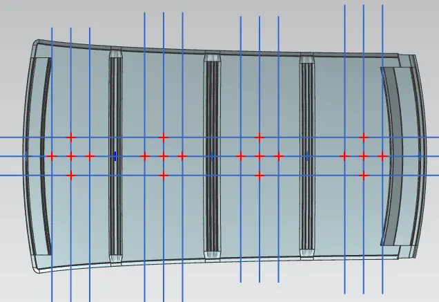
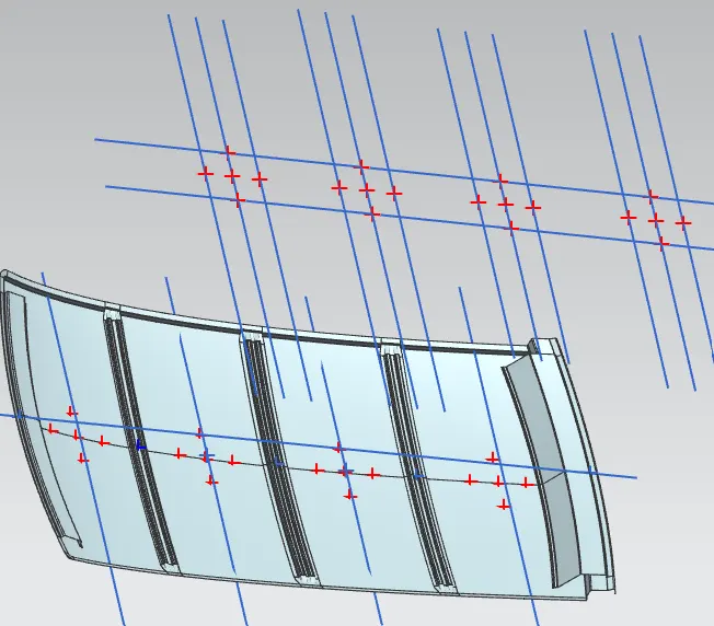
Steps to calculate snow load condition:
Steps is same as heat distortion criteria but the difference is we calculate the Rx and Ry at the centerline of the roof along the y-axis.
But additionally we have to calculate the Moment of Inertia to each reinforcement.
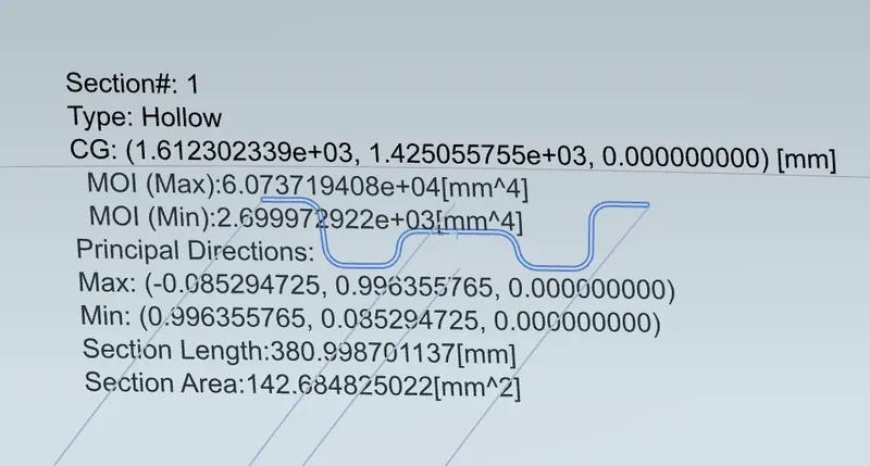
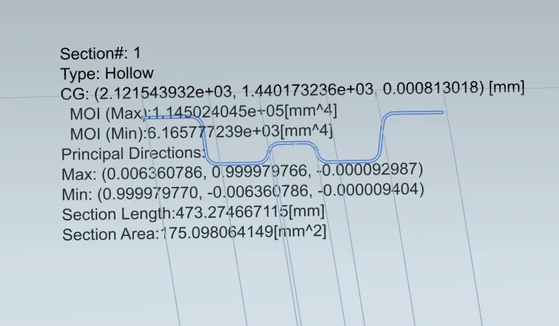
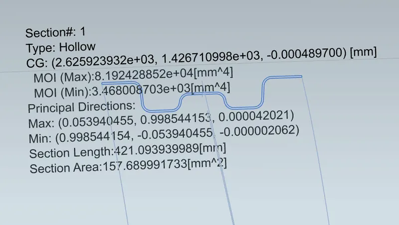
for the Iy = Geometrical moment of inertia of Roof BOW (Y cross-section )[mm4]
Now we use a sectional inertia analysis tool to calculate the MOI as follows;
Section Modulus :
Bow1
Center Roof Rail
Bow 2
Calculation:
Front Roof Rail and Bow Roof 1
Iy = Geometrical moment of inertia of Roof BOW (Y cross-section )[mm4]
Iy = 2669.9
Y= Center of Front Roof Rail to Center Bow Roof 1
Y= 479.5
Lx= Roof length in X-axis at the center line of the Front roof rail and Bow 1
Lx= 1154.9
My = Y(Ly-Y)
My = 1064681.8
α = My x Lx2 x 10-12 ,
α = 1.42006
s = Distance for which Roof BOW bears divided load [mm]
s = L1/2 + L2/2
s = 494.45
Rx = 4787.8
Ry = 2265.3
t = 0.75
Put all values in equation
Qr = [Iy x t2] / [α x s x [(Rx + Ry)/2]2 x 10-8]
Qr = 17.391
Judgment condition Qr ≥ 3.1, Condition and Position of the Bow 1 is Correct.
Result Table:
|
S.no |
Bow’s |
IY |
MY |
Alpha |
LX |
LY |
Y |
S |
RX |
RY |
t |
Q r |
OK/NG |
|
1 |
FT &1st |
2669.9 |
1064681.8 |
1.42006 |
1154.9 |
2079.2 |
479.5 |
494.45 |
4787.8 |
2265.3 |
0.75 |
17.391 |
OK |
|
2 |
1st & CR |
3468 |
1507110.8 |
1.81201 |
1096.5 |
2079.2 |
509.4 |
507 |
3755.5 |
5810.4 |
0.75 |
9.281 |
OK |
|
3 |
CR & 2nd |
6165.7 |
2856591.06 |
3.25097 |
1066.8 |
2079.2 |
504.6 |
554.4 |
4239.3 |
10632.8 |
0.75 |
3.48 |
OK |
|
4 |
2nd & RR |
0 |
-365057.6 |
-0.40209 |
1049.5 |
2079.2 |
604.2 |
302.1 |
3903.5 |
16961.2 |
0.75 |
0 |
draft analysis:
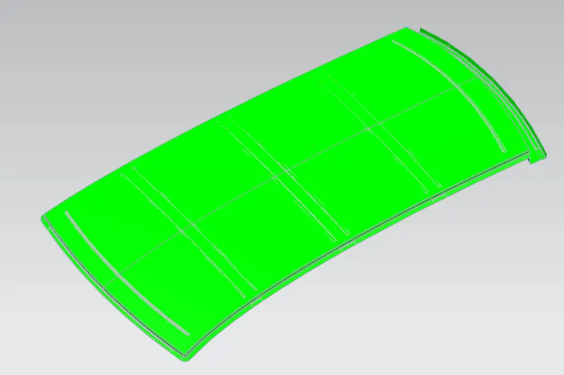
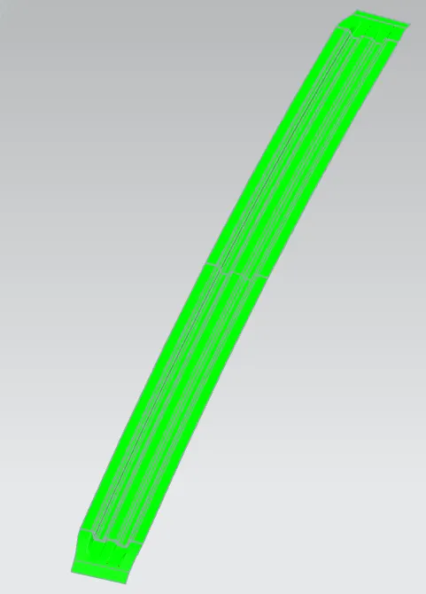
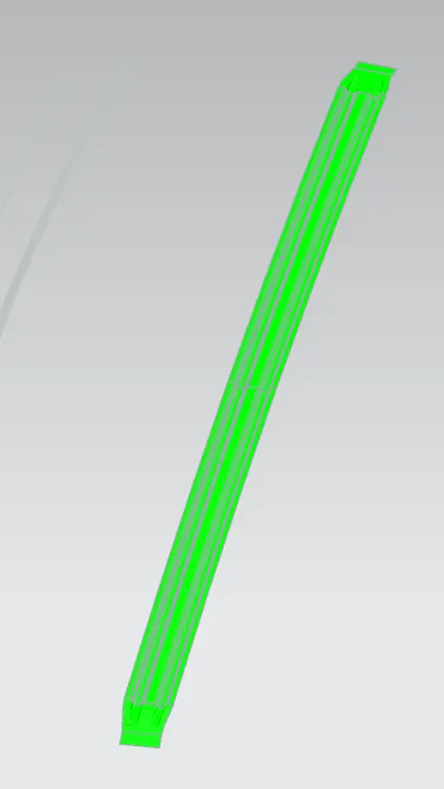
Parts cannot be ejected from the tool if it is at 90- degree for this reason, a small draft is to be provided for each surface for the components in order to easily remove the components from the mould without any defects. Draft is the angle in which the part is tapered to allow it to release. Most of the sheet metal part require minimum 7 degree to 10 degree however 7 degree is widely accepted in sheet metal components design.
Front Roof Rail Back Roof Rail
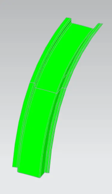
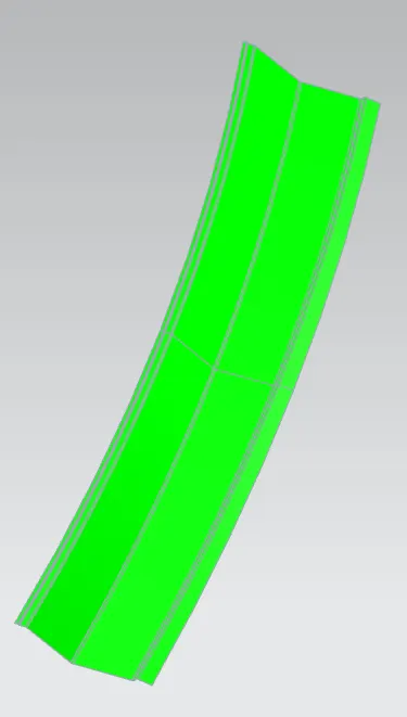
Center Roof Rail Bows
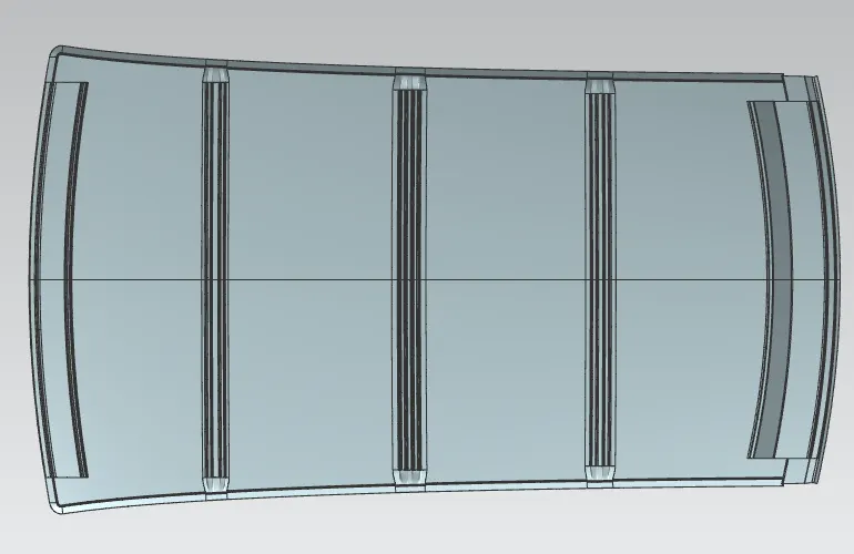
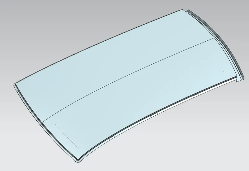
Final Roof
Conclusion:
Design of roof was done and checked for heat load and snow load criteria. Designed passed the heat load criteria and snow load criteria.