Roof Design
INTRODUCTION:
A car roof is the portion of an automobile that sits above the passenger compartment, protecting the vehicle occupants from sun, wind, rain, and other external elements.
OBJECTIVE:
Understand the design process behind the roof, components, design considerations, and the calculation behind it.
METHODOLOGY
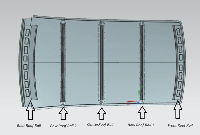
We get the Class Model of the roof from the styling team, then we will have to do all the engineering work. We create front roof rail, rear roof rail, bow roofs, and center roof rail using the given master section by considering all the design and safety norms and regulations.
COMPONENTS OF ROOF
1. Front Roof Rail
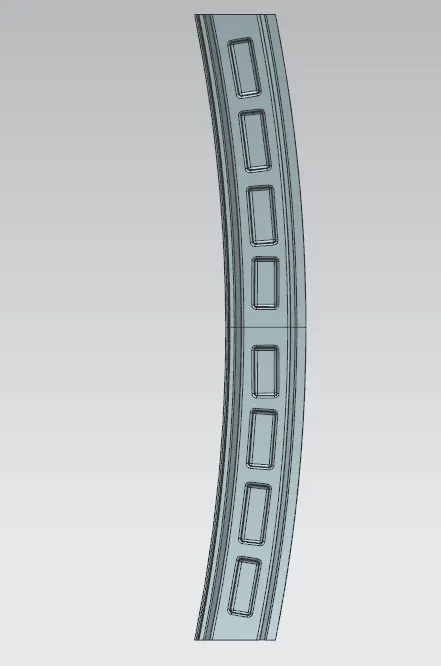
It is located on the front of the roof where the windshield joins with the roof. It was designed using the master section by considering visibility criteria, and headroom clearance of the passenger. And the rail is joined to the outer roof front side using spot welding at one side and mastic sealant at the other side.
2. Bow Roof Rail - 1
It is an additional stiffening member for the roof to increase its strength and it is located near the front roof rail, but in modern cars, there might be sunroof openings instead of a bow roof. In this, we go with a bow roof. Joining operations are done using mastic sealant.
3. Center Bow Roof
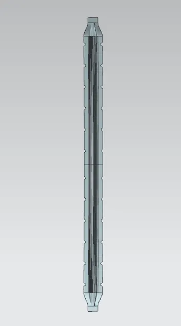
The Centre roof rail or reinforcement center is located at the center of the roof. The cross-section of this is wider than the bow roof rails because it provides more strength to the roof. Joining operations at the ends are done using mastic sealant.
4. Bow Roof Rail - 2
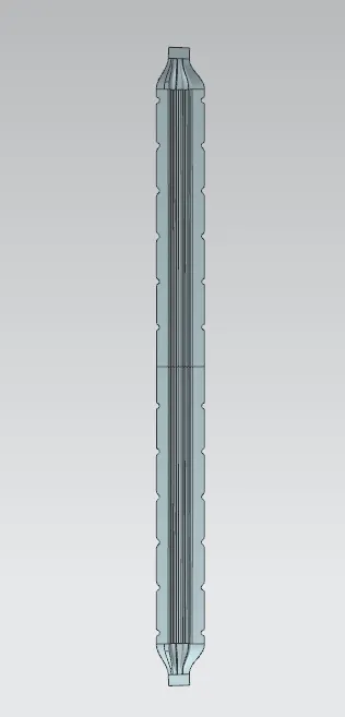
It is also an additional stiffening member for the roof to increase its strength and it is located near the rear roof rail. Joining operations are done using mastic sealant.
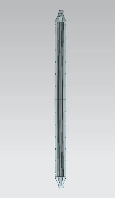
5. Rear Roof Rail
It is located on the rear side of the roof. Inputs from the backdoor are taken into consideration for designing the roof. And the rail is joined to the outer roof rear side using spot welding on one side and mastic sealant on the other side.
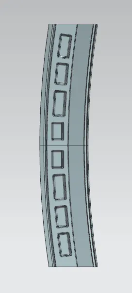
DRAFT ANALYSIS
The Draft Analysis command enables you to detect if the part you drafted will be easily removed.
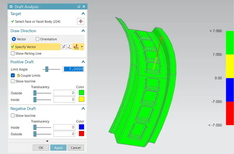
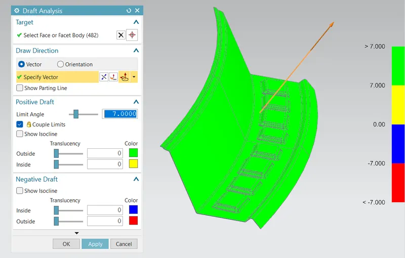
All the draft analyses were done with a standard value of 7 degrees. If it has 7 or more degrees it shows green. Below 7 degrees are shown as yellow. 0 to -7 shows blue. Less than -7 shows as red
Front Roof Rail
Rear Roof Rail
Bow Roof Rail (1)
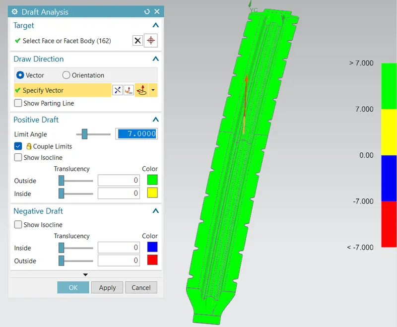
Centre Bow Roof Rail
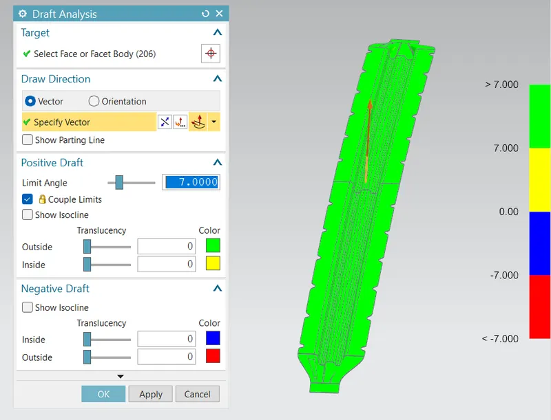
Bow Roof Rail (2)
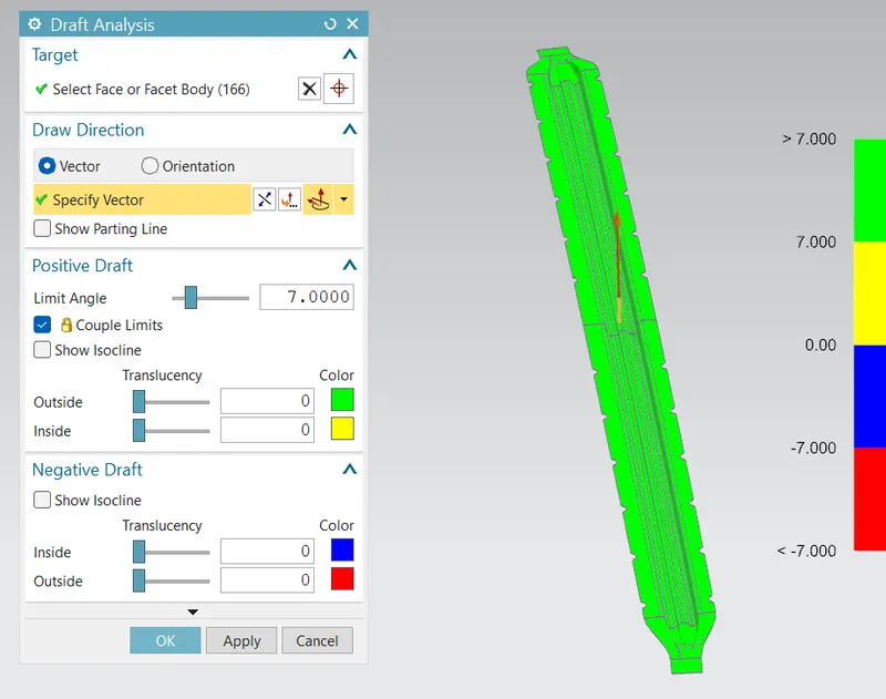
All the models satisfy the minimum 7 degrees
CALCULATIONS
1. Heat Distortion Calculation
This study is used to find out and predict the heat distortion temperature at where the material starts to soften when exposed to a fixed load. So in order to avoid bending or damage to the roof based on this calculation, we will decide the position of the roof bows on the roof.
W = [1.73 x 10^(-3) x L] + [1.85 x 10^(-8) x (R^2)/t] + [ 1.10x10^(-3) x l] - 2.68
Where,
L = Roof Length in X-Direction[mm](Roof dimension in 0-Y)
R = Roof curvature
R = 2(Rx*Ry)/(Rx+Ry)
Rx = X curvature
Ry = Y curvature
t = Roof plate thickness [mm]
l = Bow Roof Span [mm]
Judgment Condition :
OK< 2.7
| Sl No. | Bows | Rx | Ry | R | I | L | t | (R/2^t) | w | OK/NG |
| 1 | FR & 1st Bow | 5740.11 | 2391.4 | 3376.224 | 330.17 | 2027.66 | 0.75 | 2007.515 | 1.47221136 | OK |
| 2 | 1st Bow & CTR | 5058.34 | 5845.31 | 5423.425 | 425.17 | 2027.66 | 0.75 | 3224.788 | 2.021072823 | OK |
| 3 | CTR & 2nd Bow | 4044.12 | 10239.44 | 5798.208 | 441.07 | 2027.66 | 0.75 | 3447.635 | 2.142302721 | OK |
| 4 | 2nd & RR | 3288.48 | 14526.85 | 5362.938 | 407.48 | 2027.66 | 0.75 | 3188.822 | 1.985520382 | OK |
The design is ok as per the calculation
2. Snow Load Prediction Formula
We predict the snow load in this of the roof bows and then place and change the design of the load accordingly to satisfy the condition.
Qr = [Iy x t2] / [α x s x [(Rx + Ry)/2]2 x 10-8]
Note: The Qr value given over here is correct. There was a typo error in the formula given in the video.
Where,
α = My x Lx2 x 10-12 , My = Y(Ly-Y)
t = Roof plate thickness [mm]
Ly = Distance between the front and rear roof Rails on the Vehicle along with 0Y[mm]
Length of Roof panel with the center point between Roof rail Front /Rear as the front and rear reference point.
Lx = Distance between the Left and Right end of the roof on the Roof BOW [mm]
The width of the roof panel is exposed on the surface.
Y = Distance front Front Roof Rail to Roof BOW[mm]
s = Distance for which Roof BOW bears divided load [mm]
s = L1/2 + L2/2
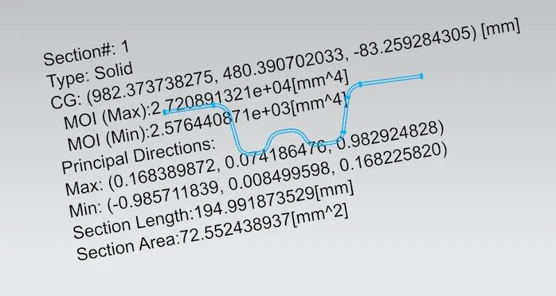
Iy = Geometrical moment of inertia of Roof BOW (Y cross-section )[mm4]
Rx = Lateral direction curvature radius of roof panel Y cross-section on Roof BOW [mm]
Roof panel curvature Radius of the Length Lx in Front view
Ry = Longitudinal Direction curvature radius of the Roof panel X cross-section on Roof BOW [mm]
Roof panel X curvature radius of length s in Side view
Judgment condition :
Qr ≥ 3.1
- Moment of inertia of Roof Bow
1. Bow Roof 1
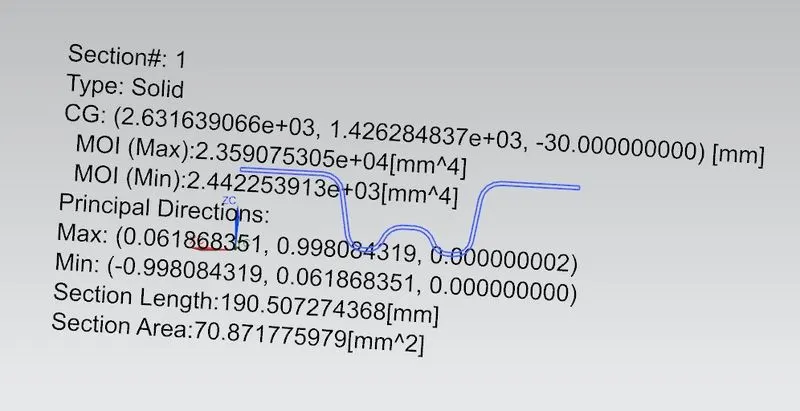
2. Center Bow Roof
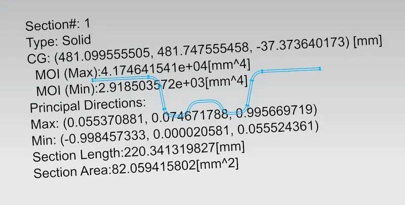
3. Bow Roof 2
| Sl No. | Bows | Rx | Ry | Lx | Ly | L1 | L2 | Y | My | s | a | t | Iy | Qr | Status |
| 1 | FR & 1st Bow | 4629.1 | 2463.44 | 1138.53 | 2027.66 | 461.98 | 503.07 | 461.98 | 723312.8464 | 482.525 | 0.937595 | 0.75 | 2.44*10^3 | 20.04653 | OK |
| 2 | 1st Bow & CTR | 3753.92 | 5746.23 | 1087.52 | 2027.66 | 503.07 | 517.73 | 965.05 | 1025471.781 | 510.4 | 1.212825 | 0.75 | 2.91*10^3 | 8.165971 | OK |
| 3 | CTR & 2nd Bow | 4241.42 | 10664.33 | 1057.34 | 2027.66 | 517.73 | 504.28 | 1482.79 | 807927.7873 | 511.005 | 0.903237 | 0.75 | 2.57*10^3 | 4.448801 | OK |
| 4 | 2nd & RR | 4020.68 | 16305.78 | 1041.7 | 2027.66 | 504.28 | - | 1987.07 | 80655.1713 | #VALUE! | 0.087522 | 0.75 | - | #VALUE! | - |
The design is ok as per the calculations
MANUFACTURING TECHNIQUES
Some of the manufacturing techniques used in roofs.
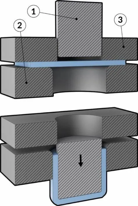
1. Deep Drawing
The deep drawing process is a forming process that occurs under a combination of tensile and compressive conditions. A flat sheet metal blank is formed into a hollow body open on one side or a hollow body is formed into a hollow body with a smaller cross-section. In the deep drawing process, the sheet metal is placed over a die cavity, held down flat against the die by a blank holder, and then pushed by a punch into a die opening in order to produce a cup-shaped, box-shaped, or concave-shaped part [22]. It is widely used for rapid mass production in the automotive industries.
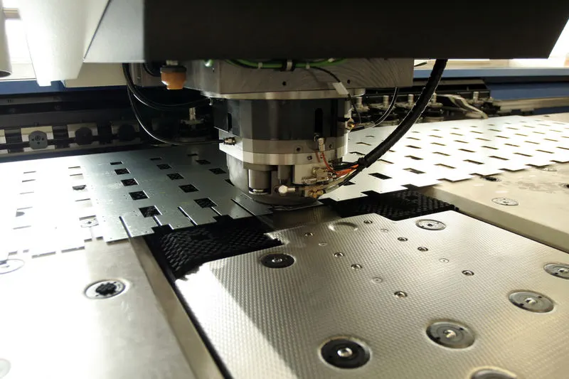
2. Stamping
Stamping (also known as pressing) is the process of placing flat sheet metal in either blank or coil form into a stamping press where a tool and die surface forms the metal into a net shape. Stamping includes a variety of sheet-metal forming manufacturing processes, such as punching using a machine press or stamping press, blanking, embossing, bending, flanging, and coining.This could be a single stage operation where every stroke of the press produces the desired form on the sheet metal part or could occur through a series of stages.
3. Hot-dip galvanizing
Galvanization is the practice of covering steel or iron with a durable zinc coating to avoid rusting. Hot-dip galvanizing is the most popular process used in galvanized sheet metal fabrication shops. This is the method of protecting GI sheet metal components by immersing them in molten zinc.
CONCLUSIONS:
We were successfully able to design the roof with all the roof rails for better support and strength by satisfying the norms and regulations by calculating the heat distortion criteria and the snow load criteria.