Roof Design
Objective
<!--[if !supportLists]-->· <!--[endif]-->To
Design an assembly of Vehicle Roof by developing the essential flanges
and creating the reinforcements for it by providing appropriate dimensions.
<!--[if !supportLists]-->· <!--[endif]-->Check
the individual part is good to draft by Draft Analysis.
<!--[if !supportLists]-->· <!--[endif]-->Perform
Curvature study on the Roof and Cheek for the Heat distortion Criteria
and Snow load Criteria to determine the feasible number and position
of the Bow Roof Rails and other reinforcements.
Introduction
The Roof of a car is often overlooked. Yet it plays a
crucial role in a vehicle’s aesthetic appeal and functionality. Car roof comes
in various designs and materials. Each serves a specific purpose and caters to
different needs. There are some types of roofs explained below,
<!--[if !supportLists]-->1. <!--[endif]-->Solid
Roof
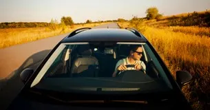
It is the most common type of roof
found in vehicles. It is typically made of steel, aluminium, or a combination
of both. Solid Roof provides excellent protection against the elements. It
provides insulation from rain, wind, and noise. They are known for their
strength and durability which contributes to the safety of the vehicle. Also,
it enhances the structural integrity of the car which improves the handling and
stability of vehicle.
Figure
1
<!--[if !supportLists]-->2. <!--[endif]-->Panoramic
Glass Roof
This type of roofs has gained
popularity in recent years. It is due to their ability to create an open and
Spacious feeling inside the vehicle.
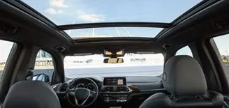
This type of roofs is typically made of tempered glass panels. It provides a
wide, unobstructed sky view for both front and rear passengers. It can be
fixed, tilted or slide type. It allows fresh air and natural light to enter in
the cabin. They add a touch of
luxury and elegance to a vehicle's interior. But it's important to consider the
potential increase in heat and glare during sunny days.
Figure
2
<!--[if !supportLists]-->3. <!--[endif]-->Convertible
Soft top
They
are also known as Rag Tops or Soft Roofs. They provide the
exhilarating experience of open-air driving. It can be folded and stowed,
allowing the driver and passengers to enjoy the freedom of the open roof. These
roofs are made of fabric materials which are lightweight and flexible. It
contributes to better fuel efficiency and improved handling. But this roof
on a car may requires more maintenance.
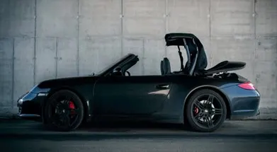
Figure 3
<!--[if !supportLists]-->4. <!--[endif]-->Retractable
Hard Top
Retractable
Hard Tops combine the best of both worlds. It offers the versatility of a
convertible with security and insulation of a solid roof. These roofs are
typically made of lightweight materials like Aluminum or its composites. They
can be electronically folded and stored in the trunk with a button. They
provide noise isolation and weather protection when closed.
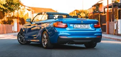
Figure 4
<!--[if !supportLists]-->5.
<!--[endif]-->Targa Top
The
Targa top is a unique roof design that originated from Porsche. This type
of car roof features a removable center section/ mid-section. It leaves a
solid structure behind the front seats and a large opening above. They provide
the convenience of removing the center panel to enjoy open-air driving. While
they are maintaining a rigid frame structure for added safety and structural
integrity which provides the security with the freedom of a convertible.
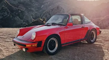
Figure 5
<!--[if !supportLists]-->6.
<!--[endif]-->Sunroof/Moonroof
Sunroofs
and Moonroofs are popular features found in many modern vehicles. They consist
of a panel made of glass or transparent material which allows sunlight and
fresh air to enter the cabin. Sunroofs are typically tilt or slide open while
moonroofs are usually fixed. They provide a panoramic view of the sky.
These roofs on cars are great for enjoying a breezy drive or
stargazing at night. But consider the potential increase in cabin heat and the
impact on headroom.
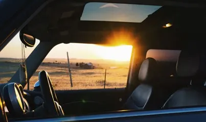
Figure 6
Design Parameters
To design
a complete Roof, it may consider the Outer Roof with its ditch area. Along with
the Outer Roof the Front Roof Rail, Bow Roof Rails and Centre Roof Rail are
also designed to provide strength to the Outer Roof. The Bow Roof Rails and the
Centre Roof Rail are connected to upper roof rail using the mastics. During
designing these parts the following criteria is considered,
<!--[if !supportLists]-->· <!--[endif]-->Visibility criteria
<!--[if !supportLists]-->· <!--[endif]-->Head room clearance
<!--[if !supportLists]-->· <!--[endif]-->Draft analysis
<!--[if !supportLists]-->· <!--[endif]-->NVH (Noise, Vibration and Hardness)
<!--[if !supportLists]-->· <!--[endif]-->Curvature study
<!--[if !supportLists]-->· <!--[endif]-->Heat distortion criteria
<!--[if !supportLists]-->· <!--[endif]-->Snow load criteria
Master Sections
Master
sections are the
cross-sectional views along with measurement details which guides us to use the
parameters to Design the part and gives a general idea about the part design. Master
sections are widely used in OEMs and automobile industries to convey the
functional requirements of the products.
Front Roof Rail
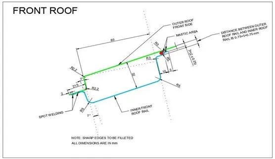
Figure 7 Master section of Front Roof Rail
The Front Roof Rail is used to support the Outer
Roof and increase the strength of the Roof. It also used to mount some features
in the cabin such as room lamp, sunglass holders and rear-view
mirror etc. The Front Roof Rail is also attached to A-pillar of the
vehicle. There are some criteria like visibility of road to driver and head
room area in cabin are kept in mind during providing width and depth of front
roof rail. Also, give a draft angle of minimum 7 degree so we can easily
produce the parts. Figure 8 shows the sectional view and the full view of the
Front Roof Rail.
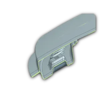
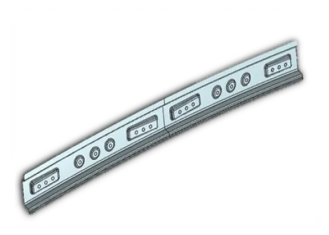
Figure 8 Front Roof Rail
Bow Roof Rails
The Bow Roof Rails are used as reinforcement
for the Outer Roof. These Roof Rails enhance the strength of Outer Roof
and reduces the NVHs values which improves the stability of the
vehicle. The number and position of Bow Roof Rail is depending on
the length and thickness of the Outer Roof and curvature study of the Roof
which is held at the end of the design.
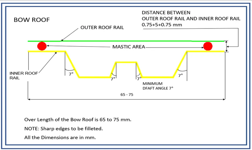
Figure
9 Master section of Bow Roof Rail 1 and 2
The figure 9 shows the Master Section of
the Bow Roof Rail which is considered during designing the Bow Roof
Rail. It consists all the necessary data required to design the Bow Roof
Rail. The figure 10 shows the Sectional view and Full view
of the Bow Roof Rail.
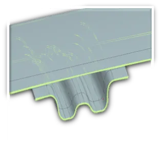
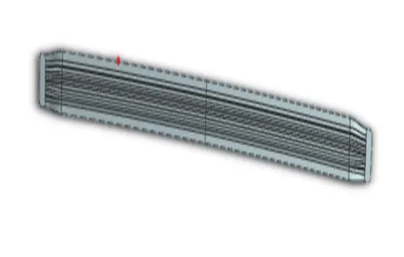
Figure
10 Bow Roof Rail 1 and 2
Centre Roof Rail
The Centre Roof Rail is used to support the Outer Roof at the mid/center. It is attached at B pillar of the vehicle and Outer Roof. The positioning of the center roof rail is also decided by the curvature study of the Roof to withstand the Heat distortion at high temperature environment and Snow load at ice places.
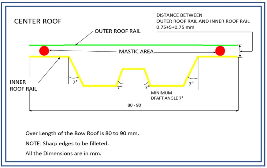
Figure
11 Master section of Centre Roof Rail
The above figure 11 shows the Master section which consist all the data necessary for designing the Centre Roof Rail. The Below figure 12 shows the Sectional and Full view of the Centre Roof Rail designed using the above Master section
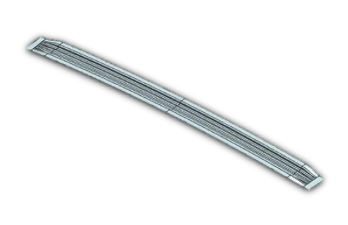
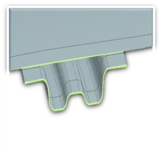
Figure
12 Centre Roof Rail and sectional view
Rear Roof Rail
The Rear Roof Rail is Designed to support the Rear part of the Outer Roof and it is also used to mount the Tail gate of the vehicle. One end of the Rear Roof Rail is attached to Outer Roof by mastic and other one is with the weld.
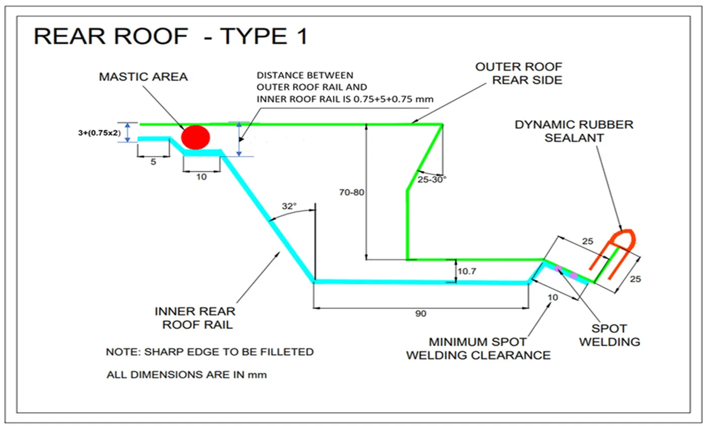
Figure
13 Master section of Rear Roof Rail
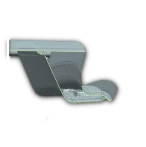
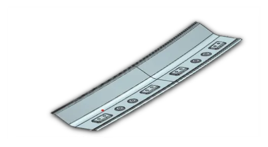
As shown in the figure 13 the master section Rear Roof
Rail is shown with all necessary data by which we can design the Rear Roof Rail.
The figure 14 shows the Sectional and Full view of the Rear Roof
Rail.
Figure
14 Rear Roof Rail and sectional view
Draft Analysis
Draft
analysis is the medium in the software by which we can analysis
that the part can be made properly by using the process of punching and
stamping along the tooling axis. For which we do draft analysis of the part
along the Tooling axis. So, we generally give a 7 degree of draft value
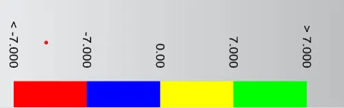
by which the part can easily be formed. All
the ranges are shown in the colors,
Figure
15 Range of Draft angles with Color Code
From the figure 15 The Green color represents
the range of 7 degree or above, yellow color represents the range
between 0-to-7-degree, Blue is for 0 to -7 and Red is used for -7
and below of it.
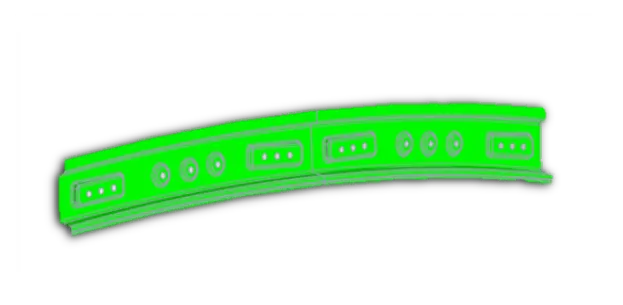
We prefer the range of 7 degree or its above i.e.
green color. Below are the all reinforcements we used for the Roof Designing,
<!--[if !supportLists]-->·
<!--[endif]-->Front Roof Rail
Figure
16 Draft analysis of Front Roof Rail
<!--[if !supportLists]-->·
<!--[endif]-->Rear Roof Rail
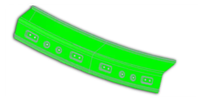
Figure
17 Draft analysis of Rear Roof Rail
<!--[if !supportLists]-->·
<!--[endif]-->Bow Roof Rail 1 & 2
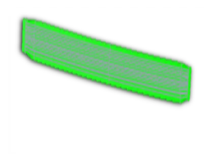
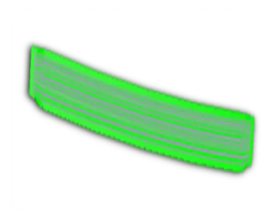
Figure
18 Draft analysis of Bow Roof Rail 1 and 2
<!--[if !supportLists]-->·
<!--[endif]-->Centre Roof Rail
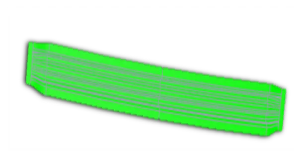
Figure
19 Draft analysis of Centre Roof Rail
Final Assembly
<!--[if !supportLists]-->·
<!--[endif]-->Front view
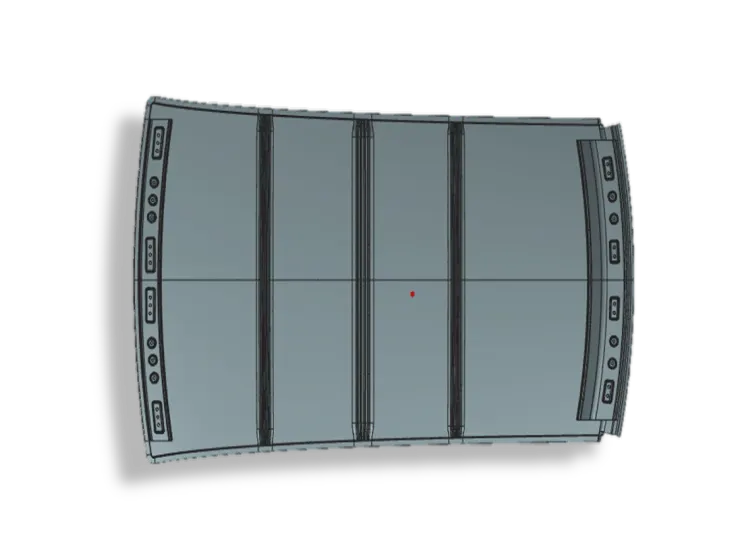
Figure
20 Front View
<!--[if !supportLists]-->·
<!--[endif]-->Side view
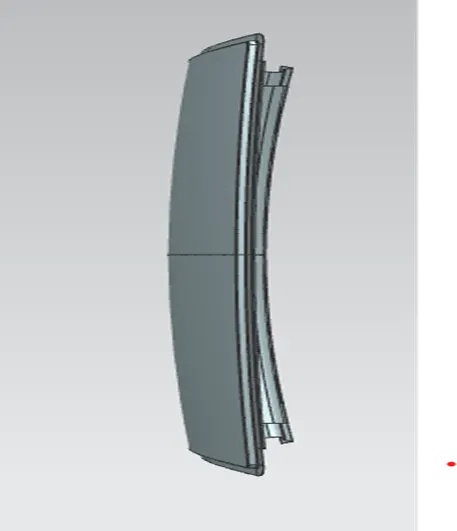
Figure
21 Side view
<!--[if !supportLists]-->·
<!--[endif]-->Top view
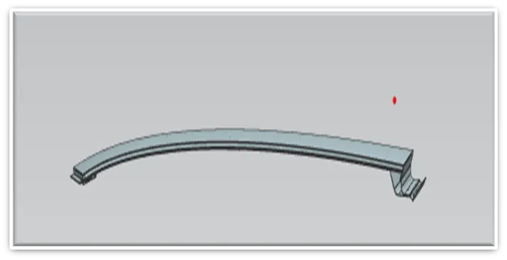
Figure
22 Top view
<!--[if !supportLists]-->·
<!--[endif]-->Isometric view
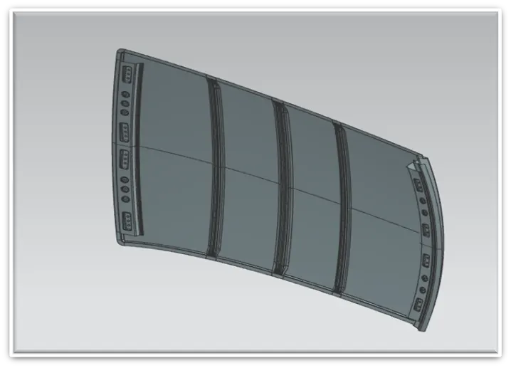
Figure
23 Isometric view
Curvature Study
It is the study of the curvature of the Roof which
shows the strength of the vehicle and Aerodynamic stability
of the vehicle. This study may include Roof Crash Test, Heat
Distortion Criteria, Snow Load Criteria etc.
<!--[if !supportLists]-->·
<!--[endif]-->Roof crash test
This test is designed by IIHS (Insurance Institute of Highway Safety) after analysing many accidents. It decides to test vehicle on some parameters to improve the vehicle and passenger safety. On the basis of those parameters IIHS gives rating to the vehicle. For rating the vehicle, they consider two things First one is how fast the car regain the original shape after roll over and second is how deep is the protrusion after the roll over.
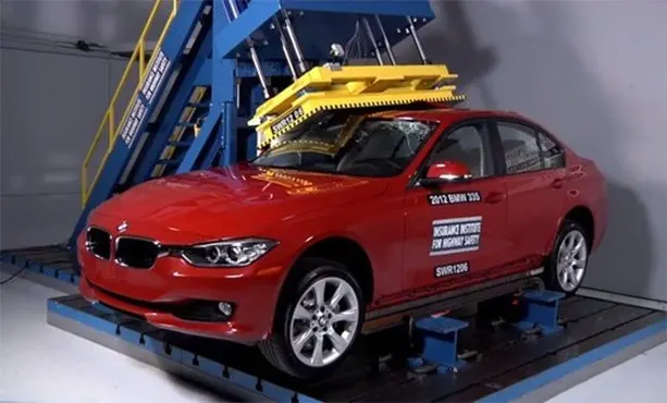
Figure 24 Crush Test at
OEMs
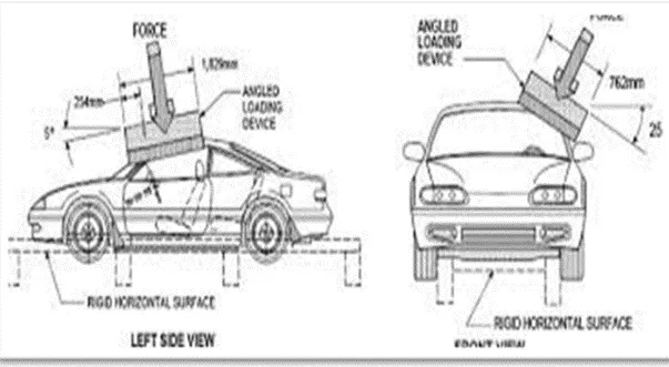
Figure 25 Side views of
Crush Testing
The
system used to test consists an upright assembly and an attached loading head
that can be fixed at varying heights from the ground as well as at pitch angles
ranging from -5 to +5 degrees to accommodate testing on the driver or passenger
side.
The
roll angle is permanently fixed at 25 degrees. Four hydraulic actuators control
the movement of the platen along two linear guides. The entire system is
mounted on a T-slot bed plate anchored to the floor of the test facility.
If
the result is not appropriate then do changes in the Roof rails to improve
strength of the roof.
<!--[if !supportLists]-->·
<!--[endif]-->Heat Distortion Calculation
The heat distortion calculation plays a major role in sheet metal usage. Heat distortion temperature is a temperature limit above which the material cannot be used for the structural application. This study is used to predict the heat distortion temperature at where the material starts to soften when exposed to a fixed load at elevated temperature. In order to avoid bending or damages on the roof, based on the heat distortion temperature, this study will help in positioning the bow roof at which roof got more strengthen
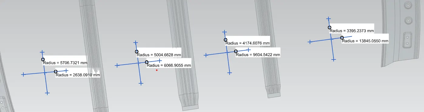
Figure 26 Rx and Ry values for the Heat distortion Criteria
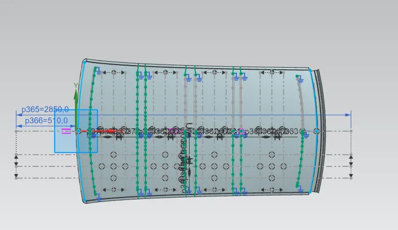
Figure
27 Projection and intersections for the measurement
Bow-Roof
prediction Formula
W=[1.73*10^ (-3) *L] +
[1.85*10^(-8)*(R^2)/t] + [1.10*10^(-3)*I] – 2.68
where,
L
= Roof Length in X-Direction[mm] (Roof dimension in 0-Y)
R
= Roof curvature
R = 2(Rx*Ry) / (Rx + Ry)
Rx
= X curvature
Ry
= Y curvature
t
= Roof plate thickness [mm]
I
= Bow Roof Span [mm]
Judgement Condition: Ok<2>
Result
of the Heat Distortion Calculation
|
Heat
Distortion Calculation |
|||||||||
|
SECTION |
Rx(mm) |
Ry(mm) |
Rx*Ry(mm^2) |
R(mm) |
t(mm) |
L(mm) |
I(mm) |
W |
RESULTS |
|
FRR-BWR1 |
2638.09 |
5706.73 |
15054878.59 |
3608.19598 |
0.75 |
2028.22 |
403.92 |
1.594269863 |
PASS |
|
BWR1-CBWRR |
6066.91 |
5004.66 |
30362816.27 |
5484.82662 |
0.75 |
2028.22 |
336.9986 |
1.941574362 |
PASS |
|
CBWRR-BWR2 |
9604.54 |
4174.61 |
40095194.86 |
5819.69068 |
0.75 |
2028.22 |
316.2908 |
2.012170872 |
PASS |
|
BWR2-RRR |
13845.1 |
3395.24 |
47007247.16 |
5453.18447 |
0.75 |
2028.22 |
522.1645 |
2.136719666 |
PASS |
The
value of w is less than the judgement condition i.e. less than 2.7 in
all the four section that shows that the positions of all the Reinforcements
are feasible and good according to the Heat distortion criteria.
<!--[if !supportLists]-->·
<!--[endif]-->Snow Load Criteria
This test is done to know the Roof Behavior when there is a snow over the Roof. Normally due to the snow load on the Roof the Rood get dented. But the Roof should be designed in such a way that when the snow is removed from the roof then the roof should go it its original position. This is the basic need for snow load criteria.
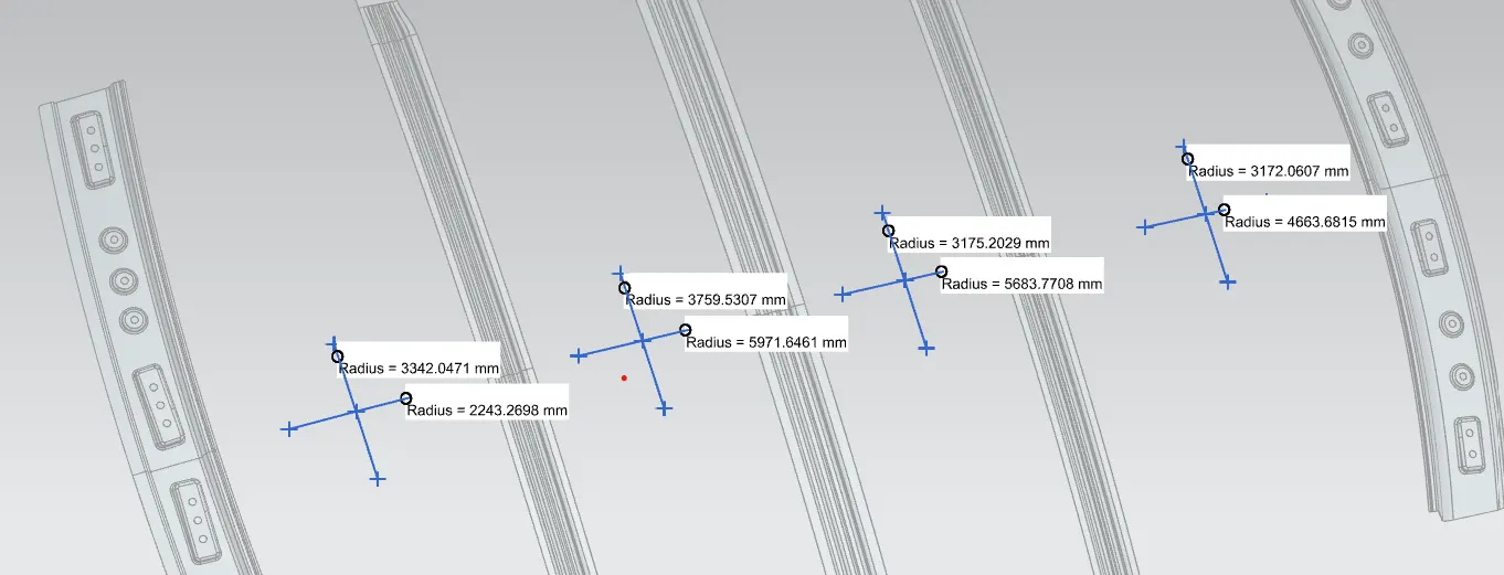
Figure 28 Rx and Ry values for Snow Load Criteria
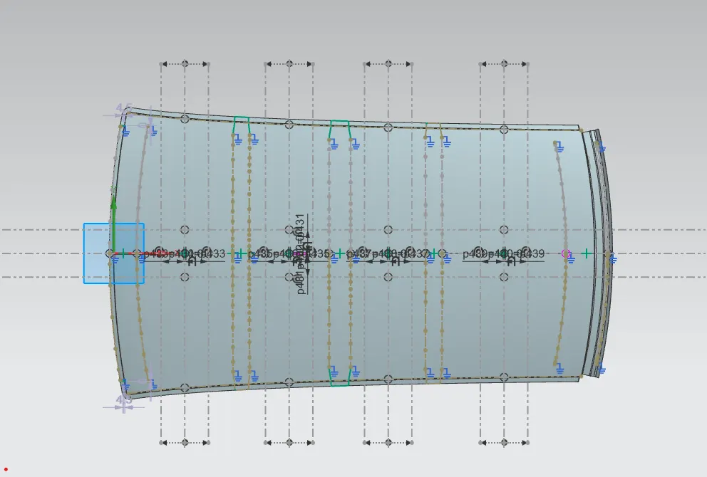
Figure 29 Projection and
intersections for the measurement
Judgement Formula for the Snow Load Criteria
Qr = [Iy * t^2] / [α*s*[{(Rx + Ry) / 2} ^2] * 10^ (-8)]
where,
α = My * Lx^2
* 10^ (-12)
My = Y (Ly
- Y)
Judgement Condition, Qr >3.1
250< s>
t = Roof plate thickness [mm]
Ly = Distance between the
front and rear roof rails on the vehicle along with 0-Y [mm] length of roof
panel with the centre point between roof rail front / rear as the reference
point of the front and rear.
Lx = Distance between the left
and right end of the roof on the roof Bow [mm] width of the roof panel exposed
on the surface.
Y = Distance from front roof
rail to bow roof rail [mm]
S = (L1/2)
+ (L2/2)
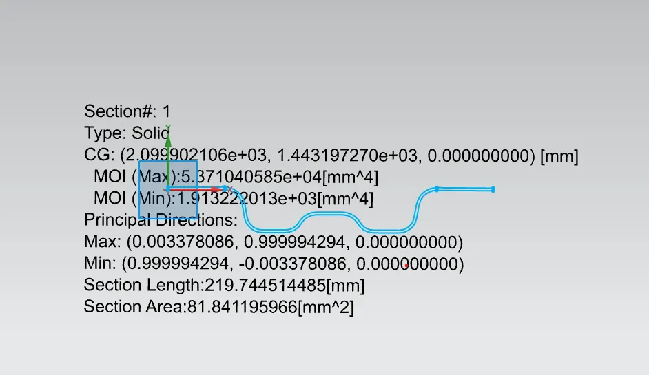
Iy = Geometrical moment of
inertia of bow roof rail (Y cross-section) [mm^4]
Rx = Lateral direction
curvature radius of roof panel Y cross-section on Bow roof rail [mm]
Ry = Longitudinal Direction
curvature radius of the roof panel X cross-section on Bow roof rail [mm]
Section Analysis:
<!--[if !supportLists]-->1. <!--[endif]-->Bow
roof rail 1
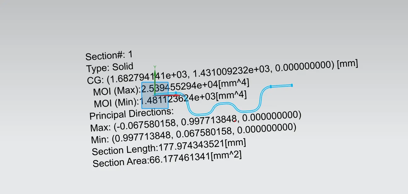
Figure
30 Iy for Bow Roof Rail 1
<!--[if !supportLists]-->2. <!--[endif]-->Bow roof rail 2
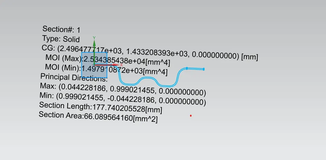
Figure 31 Iy for Bow Roof Rail 2
<!--[if !supportLists]-->3. <!--[endif]-->Centre
roof rail
Figure
32 Iy for Centre Roof Rail
Result of
Snow Load Calculation
|
Snow Load
Calculation |
|||||||||||||||
|
SECTION |
Rx |
Ry |
Lx |
Ly |
L1 |
L2 |
t |
Iy |
Y |
s |
My |
α |
Qr |
Results |
|
|
FRR-BWR1 |
3342.05 |
2243.27 |
1135.17 |
1956.24 |
496.36 |
417.54 |
0.75 |
1481.12 |
496.36 |
456.95 |
724621.9 |
0.93 |
25.04 |
PASS |
|
|
BWR1-CBWRR |
3759.53 |
5971.65 |
1087.64 |
1956.24 |
417.54 |
396.8 |
0.75 |
1913.22 |
913.9 |
407.17 |
952591.9 |
1.13 |
9.907 |
PASS |
|
|
CBWRR-BWR2 |
3175.2 |
5683.77 |
1062.67 |
1956.24 |
396.8 |
645.54 |
0.75 |
1497.91 |
1310.7 |
521.17 |
846105.6 |
0.96 |
8.624 |
PASS |
|
|
BWR2-RRR |
3172.06 |
4663.68 |
1045.55 |
1956.24 |
645.54 |
0 |
0.75 |
0 |
1956.2 |
322.77 |
0 |
0 |
#### |
|
|
As per the above Data collected from
the Design, the value of Qr is above 3.1 means the Snow Load
Criteria is Passed but the value of s is not lying between the
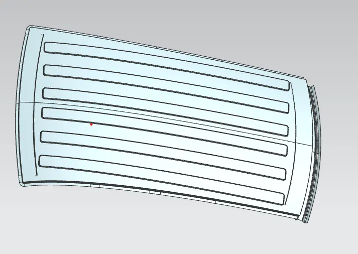
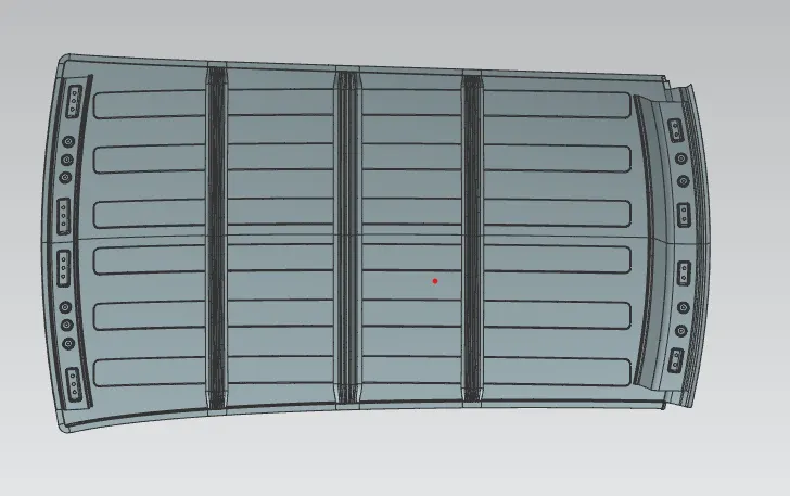
range. It means that the number of Bow Roof Rails are have to increase or we
can provide Embosses to the Outer Roof to increase the strength of the roof.
Embossed Outer Roof
<!--[if !supportLists]-->·
<!--[endif]-->Outer Roof Upper side
Figure
33 Embossed Outer surface
<!--[if !supportLists]-->·
<!--[endif]-->Lower side view
Figure
34 Lower side of Improved Roof
Conclusion
Design of Roof was successfully completed using the
Siemens NX as per the given Master sections. Checked the manufacturability of
the part by doing the Draft analysis and section analysis also completed the
curvature study to check the position and number of Bow Roof Rails are good to provide
proper strength and stability to the vehicle.
Link: https://drive.google.com/file/d/1YMfvxhMdwcbD1UZ3YvHXDAMmaJAM_Xcv/view?usp=sharing