Roof Design
ROOF DESIGN
OBJECTIVE:-
- For the given roof styling,create an assembly by developing the essential flanges for the outer roof and creating the reinforcements.
- Validate the created design with two criterion namely HEAT DISTORTION CRITERIA & SNOW LOAD CONDITION.
- IF the created design satisfy the criteria then its good,if not then suggest the changes which are practically possible.
WHAT IS ROOF?
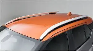
An automobile roof is the portion of automobile that sits above the passenger compartment,protecting the vehicle occupants from sun,wind,rain & other external elements.
TYPES OF ROOF'S
- SUNROOFS :-
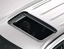
Many cars come with sunroof's,which are small openings in the roof that can be titled open or fully retracted to let in sunlight and fresh air.Sunroofs can be made of tempered glass or polycarbonate and may have a manual or power operated mechanism.
- HARDTOPS:-
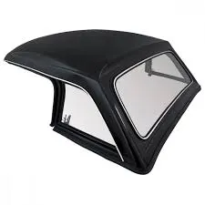
Hardtop roofs are made of metal panels or composite materials.They offer better insulation and security compared to soft tops but can be heavier and take longer to retract.
- Soft-top convertible:-

Made of fabric or Vinyl,soft-top roofs are lightweight and fold down neatly when not in use.They Provide a classic convertible experience and are relatively easy to operate.
- TARGA-TOP:-
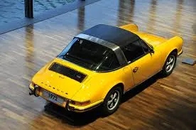
It is a semi convertible car body style with a removable roof section and full-width roll bar behind the seats.The rear window is normally fixed,but on some targa models,it is a removable plastic foldable window,making it a convertible-type vehicle.
- GLASS ROOF:-
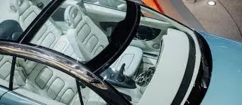
Some cars feature glass roofs,which can either be fixed or panoramic.Fixed glass roofs are made of tempered glass and provide a clear view of the sky.Panoramic roofs extend over a larger portion of the Car's roof, offering a more open feel to the cabin.These roofs often have a sunshade or tinting to control sunlight and heat.
Some information about test's that are carried out on automotive passenger car roofs to ensure safety,durability and compliance with regulatory standards.
- ROOF CRUSH TEST This test evaluates the structural integrity of the roof by applying vertical force to simulate a rollover accident.the roof must withstand a certain amount of force without collapsing to meet safety standards.
- STATIC LOADING TEST similar to the roof crush test,this test applies a static load to the roof to measure its strength and deformation characteristics.It assesses the roof's ability to support weight without excessive deflection or failure.
- DYNAMIC ROLLOVER TEST In this test,the vehicle is subjected to dynamic maneuvers to simulate real-world rollover scenarios.It assesses how the roof structure performs under dynamic loads and determines its ability to protect occupants in rollover accidents.
- WATER LEAK TEST This test evaluates the effectiveness of seals and weatherproofing measures by subjecting the vehicle to water spray or immersion to detect any leaks in the roof or sunroof system.
- WIND NOISE TEST wind tunnel testing is often conducted to assess the aerodynamic performance of the vehicle,including the roof design.Engineers analyze airflow patterns and measure wind noise levels to optimize the roof shape and reduce noise inside the cabin.
- SUNROOF OPERATION TEST For vehicles equipped with sunroofs,functional tests are performed to ensure smooth and reliable operation,including opening,closing,tilting & sunshade operation.
- DURABILITY TESTING automotive roofs are subjected to long-term durability testing to assess their resistance to factors like UV exposure ,thermal cycling,corrosion,and mechanical fatigue.
DESIGN APPROACH:-
INPUT I GOT:-
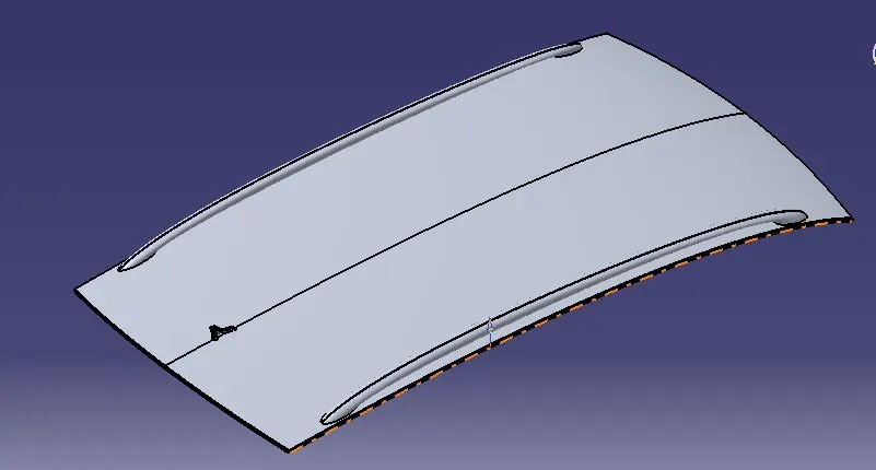
the input i received is outer panel Skin surface.
Initially the assembly file is created by copying this outer surface & paste with link in every other file & saving it with other names ,so that the outer panel surface act as reference to create other entities.
I opted to go with simple roof panel design.
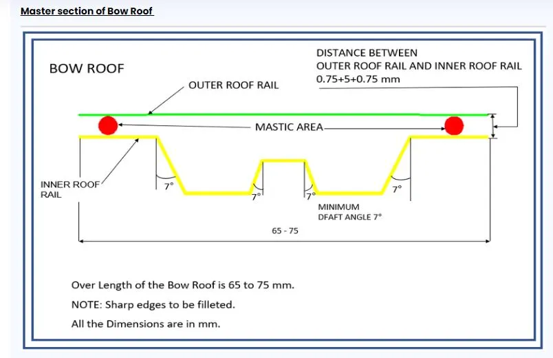
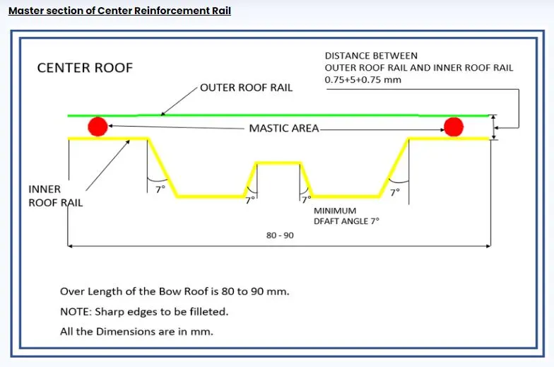
the design of outer panel & front roof rail,rear roof rail goes in parallel manner from the available mastersections are as follows:
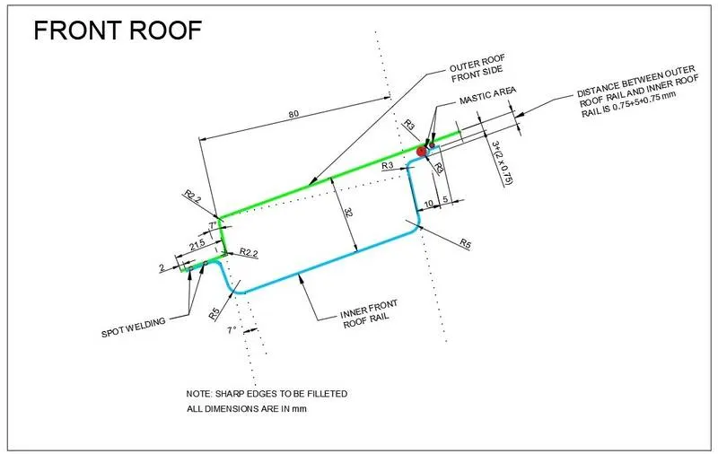
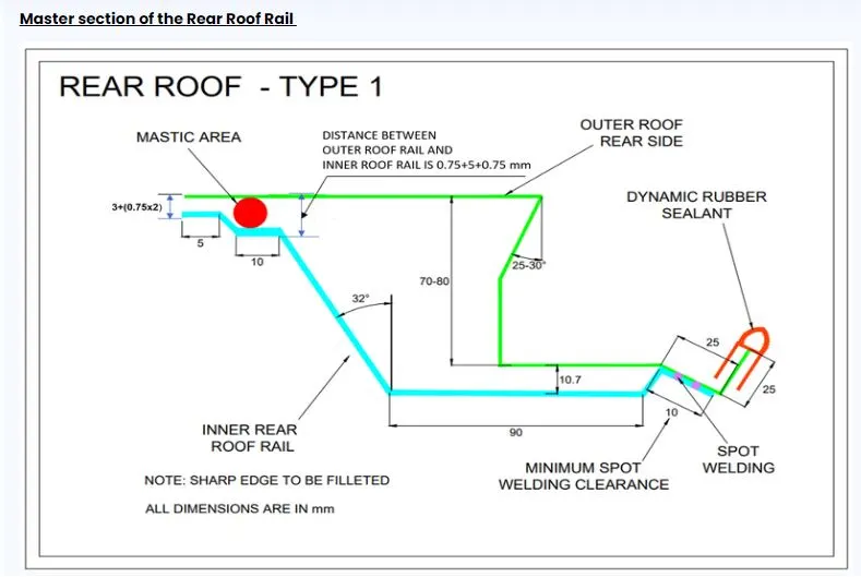
OUTER PANEL:-
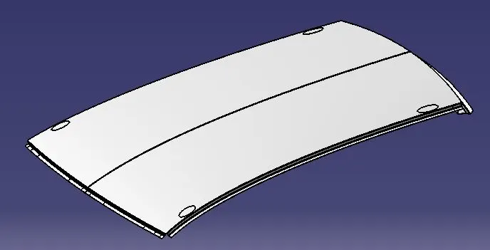
As mentioned earlier the outer panel design is done parallelly with front roof rail & rear roof rail.
the flanges are created considering 7 deg angle for tooling purpose.
Commands that are used while creating outer panel are as follows;-
- Sweep
- Extrapolate
- join
- split
- fill
- corner
- fillet
- boundary
- symmetry.
thickness:0.75 mm
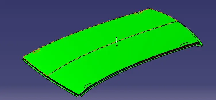
DRAFT ANALYSIS ON OUTER PANEL:-
DRAFT ANGLE= 7 DEG.
FRONT ROOF RAIL:-
The FRR is created by following mastersection provided & using commands that are listed below.
thickness =0.75mm
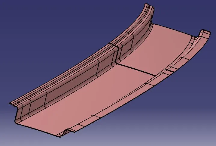
Commands used while creating it are as follows:-
- sweep
- offset
- extrapolate.
- split
- trim
- join
- fillet
- extract
- symmetry
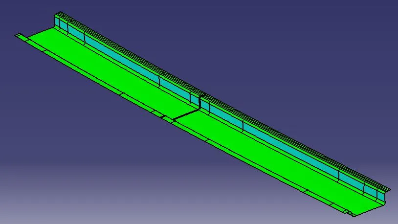
here as shown in attached picture above one face is clearly not coming out for 7 deg criteria.So,this face needed to provide slightly more angle with vertical axis.
REAR ROOF RAIL:-
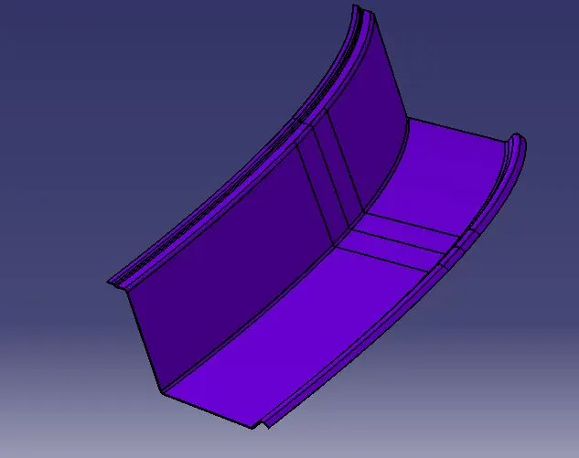
Rear roof rail is created with he help of mastersection.
thickness =0.75 mm
Commands used while creating it are as follows:-
- extract
- join
- offset
- parallel
- sweep
- fillet
- split
- trim
- symmetry.
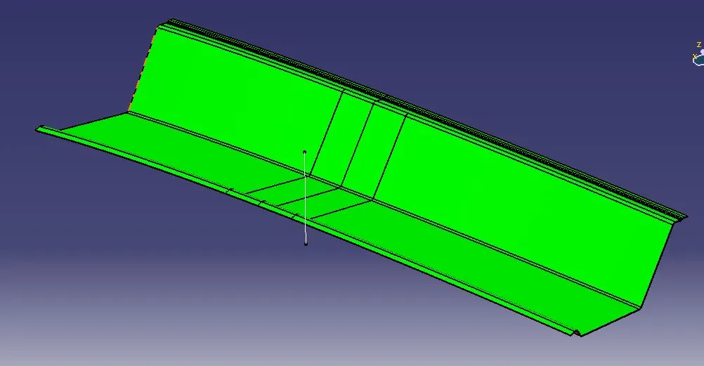
as shown in above attached picture the created REAR ROOF RAIL is clearly coming out for 7 deg.
So,From manufacturing point of view it is clear with steel as a material.
CENTER ROOF RAIL:-
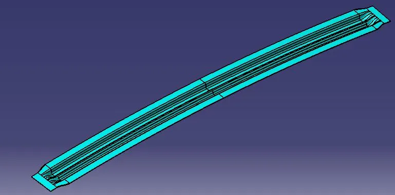
Center roof rail is created with the help of mastersection,as from mastersection it is clear that mastic is used to join it with outer panel,while to join it at edges i considered spot weld for joining purpose.
For spot welding consideration 20 mm strip is left to join with lateral sides of roof.
thickness =0.75mm
Commands used while creating it are as follows:-
- Boundary
- offset
- sweep
- join
- trim
- split
- extract
- fillet
- symmetry
- sew
- intersect
- fill.
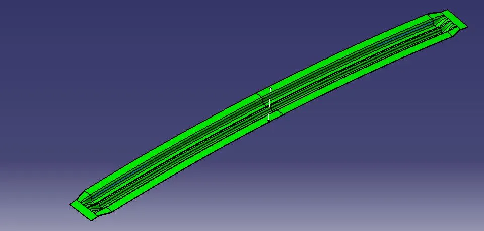
as from above picture it is clear that it is manufacturable with 7 deg considering steel as material.
BOW ROOF RAIL 1:-
It is also designed on the basis of mastersection provided.
thickness=0.75 mm
For spot welding it with lateral sides of outer panel 20 mm strip is kept there.
Notches provided using design criteria as follows:
-minimum distance between consecutive notches as 3.2 mm
-Near bends,notches must be atleast 3 times material thickness + Bend radius.
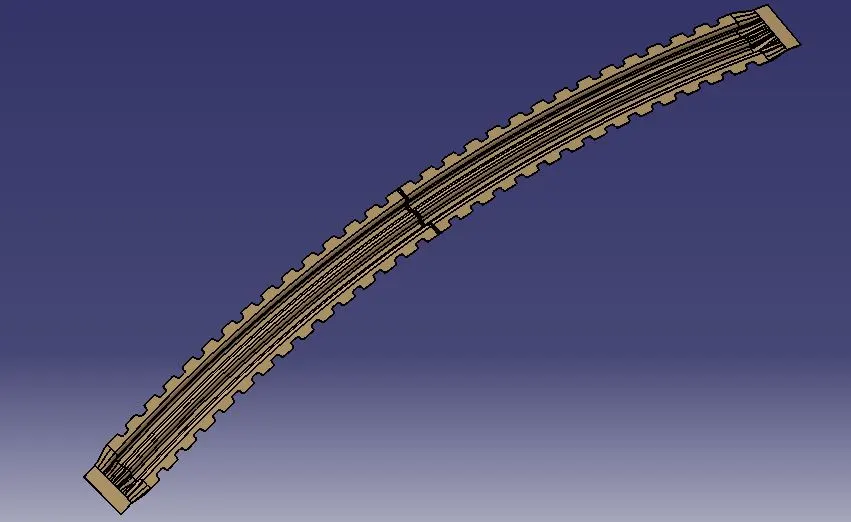
Commands used while creating it are as follows:-
- parallel
- offset
- extrapolate
- trim
- join
- symmetry
- extrude
- split
- sweep
- fillet
- blend
- intersect
- fill.
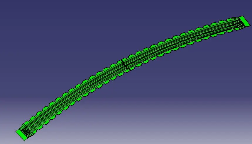
As from above picture it is clear that it is manufacturable with 7 deg considering steel as material.
BOW ROOF RAIL 2:-
It is also designed on the basis of mastersection provided.
thickness=0.75 mm
For spot welding it with lateral sides of outer panel 20 mm strip is kept there.
Notches provided using design criteria as follows:
-minimum distance between consecutive notches as 3.2 mm
-Near bends,notches must be atleast 3 times material thickness + Bend radius.
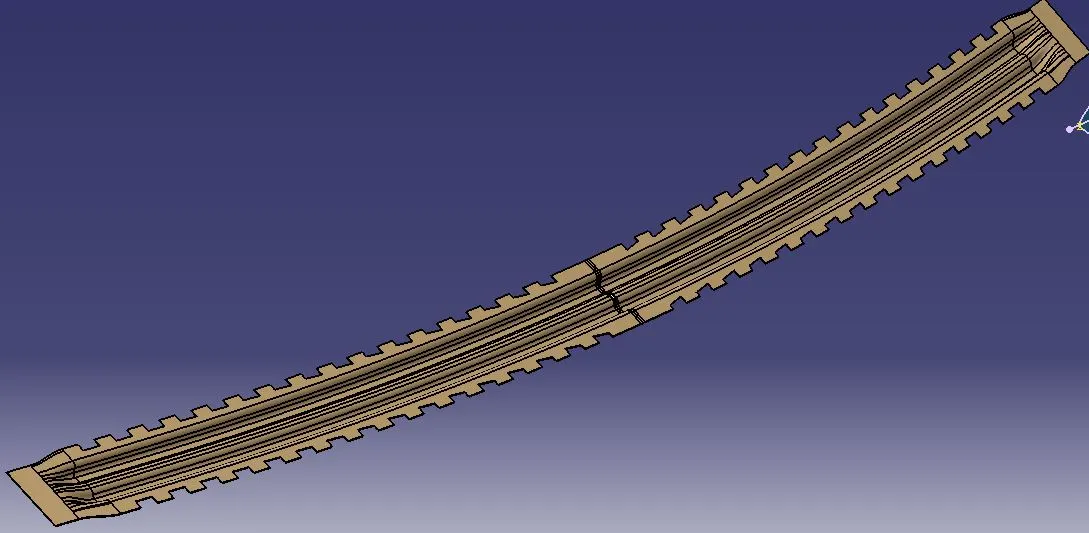
Commands used while creating it are as follows:-
- parallel
- offset
- split
- join
- symmetry
- extrude
- sweep
- fillet
- extract
- blend
- sew
- intersect
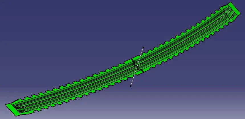
As from above picture it is clear that it is manufacturable with 7 deg considering steel as material.
FINAL OUTCOME:-
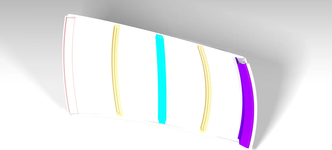
Manufacturing methods used for joining:-
Spot welding:- spot welding is a process used to join two or more metal surfaces together by applying pressure and passing an electric current through them.This creates heat,which melts the metal at the point of contact,forming a weld.Its commonly used in automotive and manufacturing industries for its speed and efficiency.
HEAT DISTORTION CRITERIA :-
W = [1.73 x 10^(-3) x L] + [1.85 x 10^(-8) x (R^2)/t] + [ 1.10x10^(-3) x l] - 2.68
Where,
L = Roof Length in X-Direction[mm](Roof dimension in 0-Y)
R = Roof curvature
R = 2(Rx*Ry)/(Rx+Ry)
Rx = X curvature
Ry = Y curvature
t = Roof plate thickness [mm]
l = Bow Roof Span [mm]
Judgment Condition
OK< 2.7
Heat Distortion Criteria:
Introduction
Heat distortion temperature is the temperature at which the metal softens and deforms under a specific load.
This study is done to check the ability of the roof to withstand high temperature with respect to the positioning of the reinforcements which contribute to increased strength.
Why Heat Distortion Criteria?
- The use of high-tensile steel sheets on car bodies has increased, and the weight of bodies has decreased, for enhance fuel economy.
- by fabricating pieces from thinner sheets. The surface areas of outer panels such as a roof panel and door outers are large, so the effects of weight reduction are also large and thereby the needs for thinner panels are high.
- Some studies have noted issues with the outside quality where, when thinner outer panels are employed, the surfaces of shells bend owing to thermal strain during the painting and drying processes in addition to issues with the stamping performance (hence, referred to as thermal distortion).
- The washing, electrodeposition, sealing, and finish coating steps are all included in the painting of a vehicle's body. An automobile body is submerged in an electrocoating solution during the electrodeposition process to create an electrodeposited film.
- The body is then put through the drying process, where hot air from a furnace is used to dry the electrocoating solution. If thermal distortion is discovered, it requires a significant amount of labour -hours for reworking and checks for numerous parts and across multiple manufacturing processes.
- Thermal distortion is frequently evaluated by the exterior check conducted for completed vehicles with various parts installed.
- Countries where the summer is high, there are chances of heat distortion due to sun heat. When the radiation of sun falls on the form of your car, then due to that heat, thermal expansion occurs and due to some thermal expansion, possibility of hanging the roof of the car is more in that area and the roof of your car becomes weak in that area.
- By this calculation we verify these things whether your roof will be able to withstand in that condition or not?
- If so that the area is not able to tolerate this condition then we have to give better support on that area to make your roof stronger.
Procedure followed:-
To carry out analysis another part file is created & all the final surfaces are copied & paste with link in that particular part.
Another Geometrical set is created to proceed for analysis using heat distortion criteria.plane is created parallel to outer panel.
Initially a 0-Y line is created and then with a parallel command it is offsetting to 300mm,later on using parallel command selecting both sides with a value of 100 mm two other lines are created,mid-point for every two horizontal lines are created and vertical line is drawn through it and again two lines are offsetted from this line with the use of parallel command with the value of 100 mm
The copied surfaces are projected on plane one by one later on using intersection command points are created on 0-Y line.Similar manner points are created with the use of intersection command with other lines and those outcomes are act as base for Rx and Ry.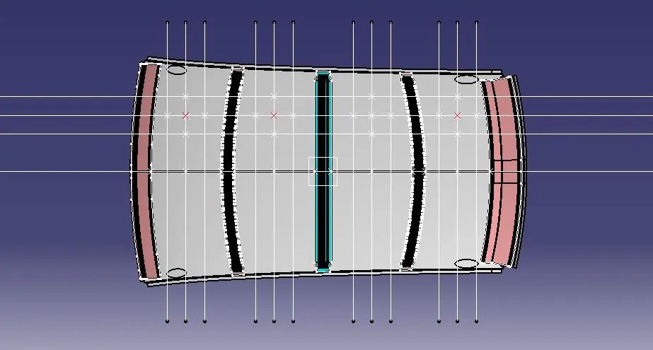
Those points are then projected on outer panel using project command and result of it are as follows.
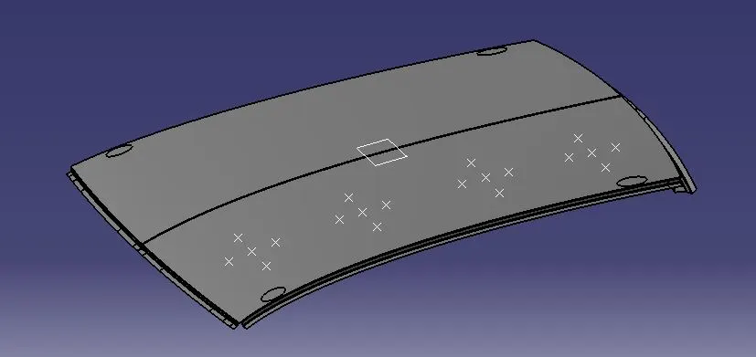
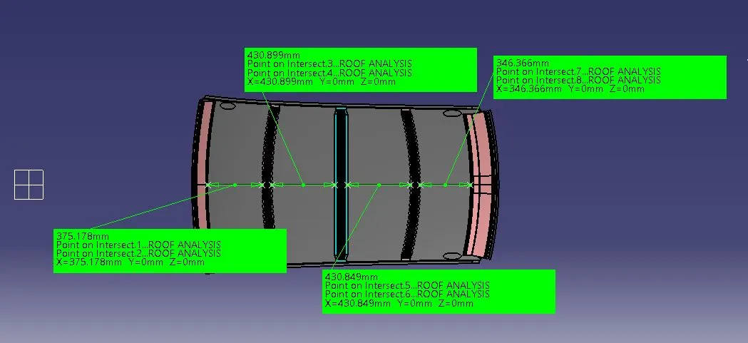
ROOF BOW Span
With the use of projected points on 0-Y line Bow Roof spans are measured.
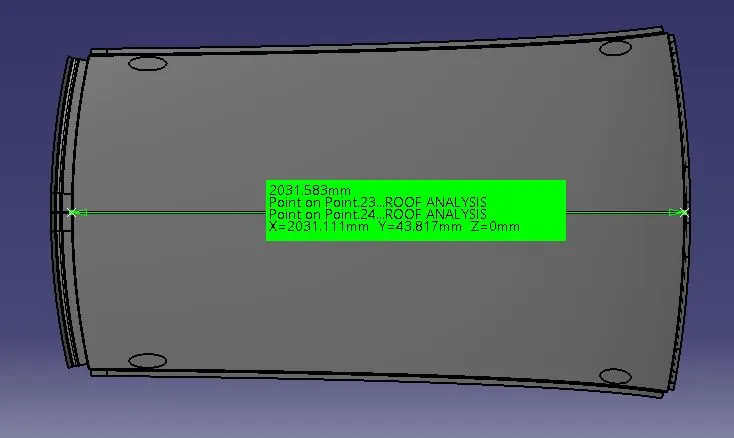
Roof Length in X-Direction
It is measured neglecting ditch areas
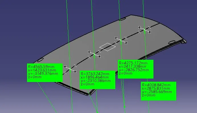
Rx on each point is created using arc with 3 points,results of which are as shown below.
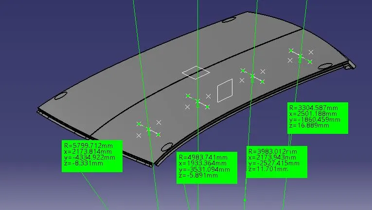
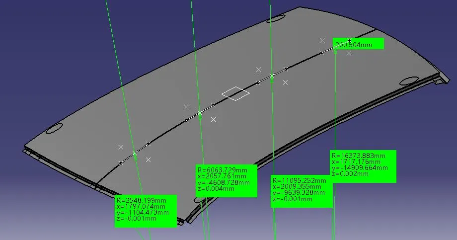
Ry on each point is created using arc with 3 points,results of which are as shown below.
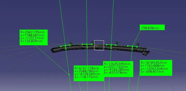

Conclusion:- The designed roof is Passing the HEAT DISTORTION CRITERIA.
SNOW LOAD CRITERIA :-
Qr = [Iy x t2] / [α x s x [(Rx + Ry)/2]2 x 10-8]
Note: The Qr value given over here is correct. There was a typo error in the formula given in the video.
Where,
α = My x Lx2 x 10-12 , My = Y(Ly-Y)
t = Roof plate thickness [mm]
Ly = Distance between the front and rear roof Rails on the Vehicle along with 0Y[mm]
Length of Roof panel with the center point between Roof rail Front /Rear as the front and rear reference point.
Lx = Distance between the Left and Right end of the roof on the Roof BOW [mm]
The width of the roof panel is exposed on the surface.
Y = Distance front Front Roof Rail to Roof BOW[mm]
s = Distance for which Roof BOW bears divided load [mm]
s = L1/2 + L2/2
Iy = Geometrical moment of inertia of Roof BOW (Y cross-section )[mm4]
Rx = Lateral direction curvature radius of roof panel Y cross-section on Roof BOW [mm]
Roof panel curvature Radius of the Length Lx in Front view
Ry = Longitudinal Direction curvature radius of the Roof panel X cross-section on Roof BOW [mm]
Roof panel X curvature radius of length s in Side view
Judgment condition
Qr ≥ 3.1
250 ≤ s ≤ 380
SNOW LOAD PREDICTION
- Snow Load Criteria study is done to check the withstand ability when the snow loads over the roof during winter in snow fall regions. This study will also analyse the roof that whether the permanent deformation occurs after removing the snow load. That it may bend but needs to be bounce back to its original position.
- roof design must pass through these calculations to ensure that it has sufficient stiffness to withstand the load due to accumulation of snow over the roof.
Procedure followed:-
As we approached earlier plane is created and 0-Y line is created and with the use of parallel command with a value of 100mm with both side option 2 equidistant lines are created from 0-Y line.
With the use of project command all other 5 surfaces are projected on plane & with the use of 'intersection' command,points are created on 0-Y line as well as on other lines. Multiple intersected points are obtained from this process and it acts as base for following process.
As these points are projected on outer panel.
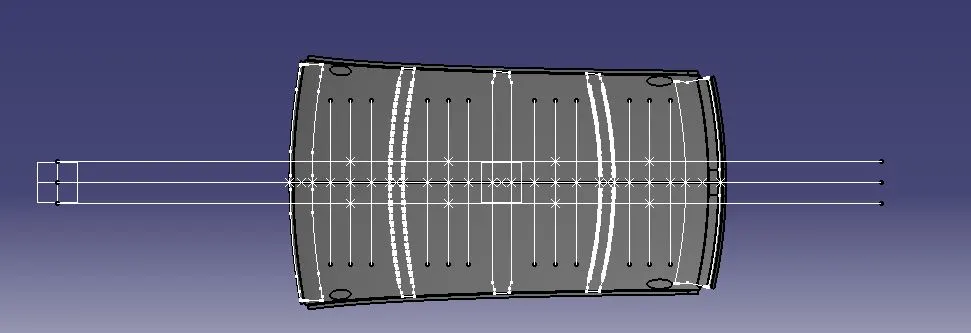
Ly is measured on 0-Y line between center point of FRL & RRL.
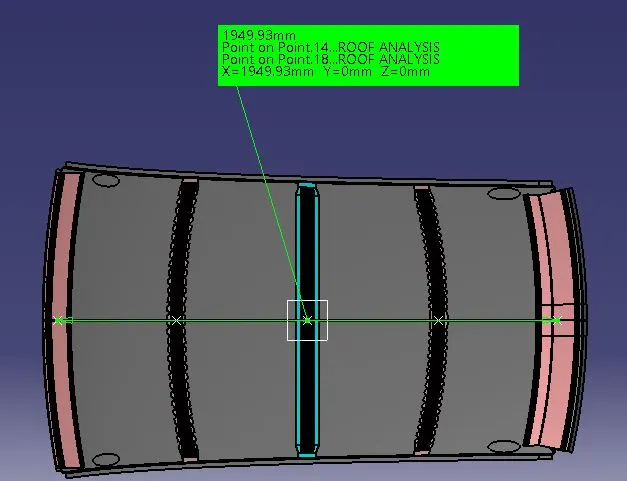
Lx for each case is measured from center point obtained between two Rails center and extracted line from lateral edges.
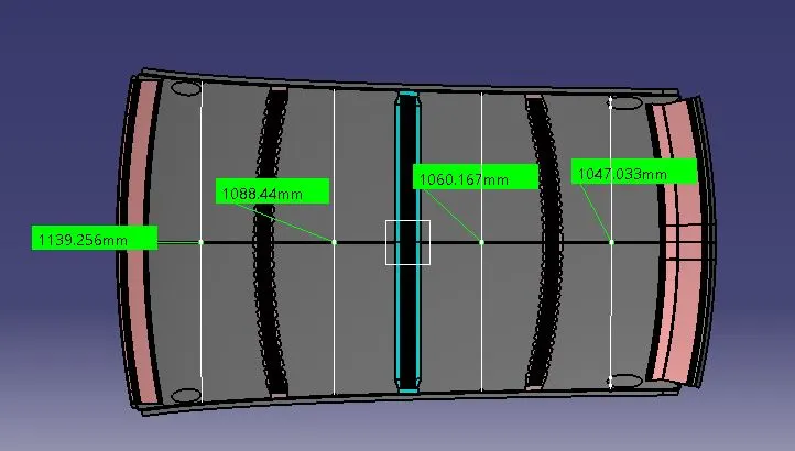
For L1 & L2
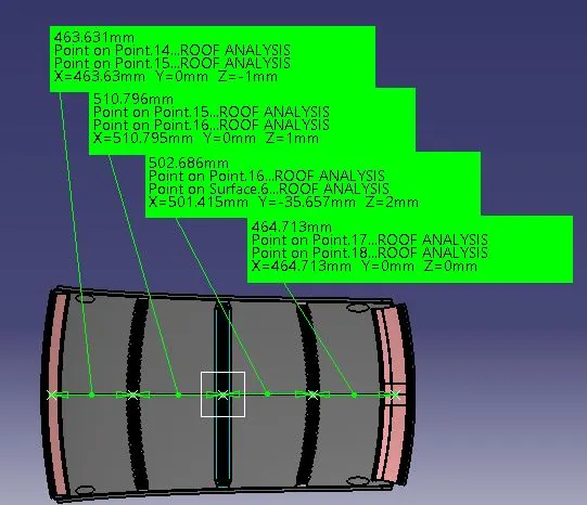
Y for each case
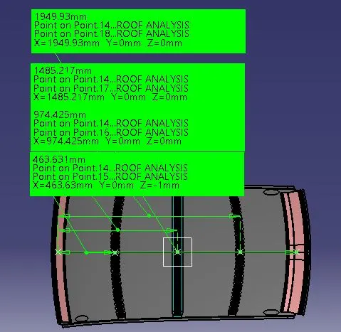
Rx for every case is created using 3 point arc from projected points.
Ry for each case is created using 3 points arc from projected points.
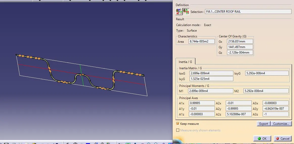
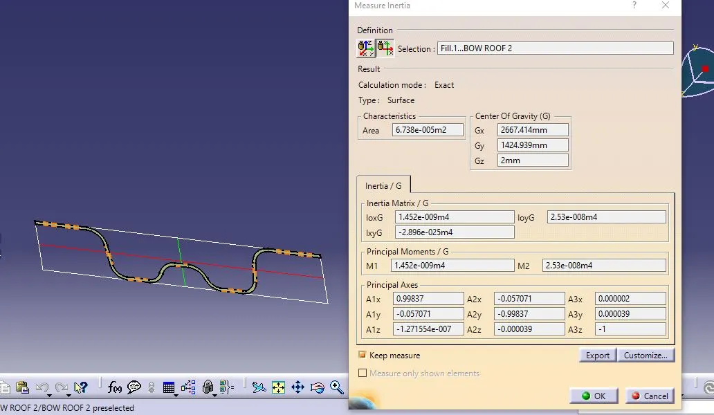
MOI is calculated on BOW ROOF 1 by using intersection command with plane(0-Y plane) and solid body and then create surface with fill command,use those fill surface for MOI.
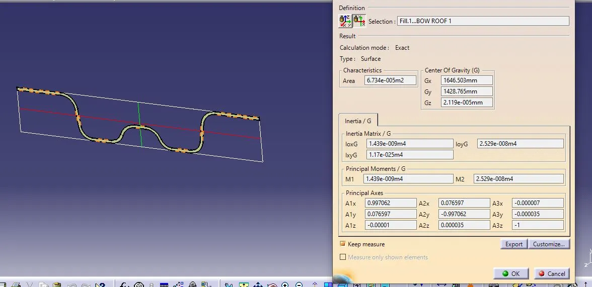
Similar approach is followed in Bow Roof 2 & central roof rail,as done in BOW ROOF 1.

Conclusion:- The designed Roof is satisfying the SNOW LOAD CONDITION CRITERIA.