Roof Design
In this Challenge I am are going to construct Roof Design using NX CAD and going to check the Heat Distortion and Snowed Condition.
The Roof is one of the important part in the car which provide passengers from Sun light, Rain, Wind and during Accident. The Roof Part of the Car is Designed with many Styling features but it also have to be designed with the good Strength to safe guard the passenger.
The common problem which the Roof faces are if Higher Heat falling in the Roof directly from the Sun, it reduces the Strength of the Roof. In winter the fall of snow settle on the Roof top of the Car and increase the weight on the Roof. The increase in the load makes the Roof to dent and decrease the Strenght of the Roof.
So in this Challenge I am going to check the Heat Distortion and the Snowed Condition for the Constructed Roof.
At first the Roof Assembly is created and then the Outer Roof Part is Imported. Then in the Assembly workbench the New Component options is selected and then the Component name and Save locations is selected. The First Component which created is Front Roof Rail, the Sketch is constructed and then the Swept Option is used to Create a Part. Then the Part is Thicken with 0.75mm.
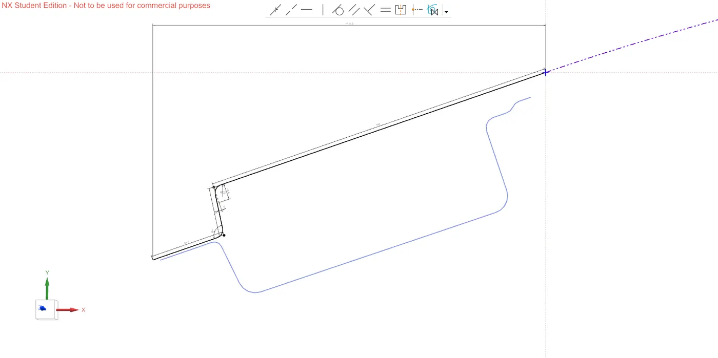
Fig 1. Sketch for Front Roof Rail
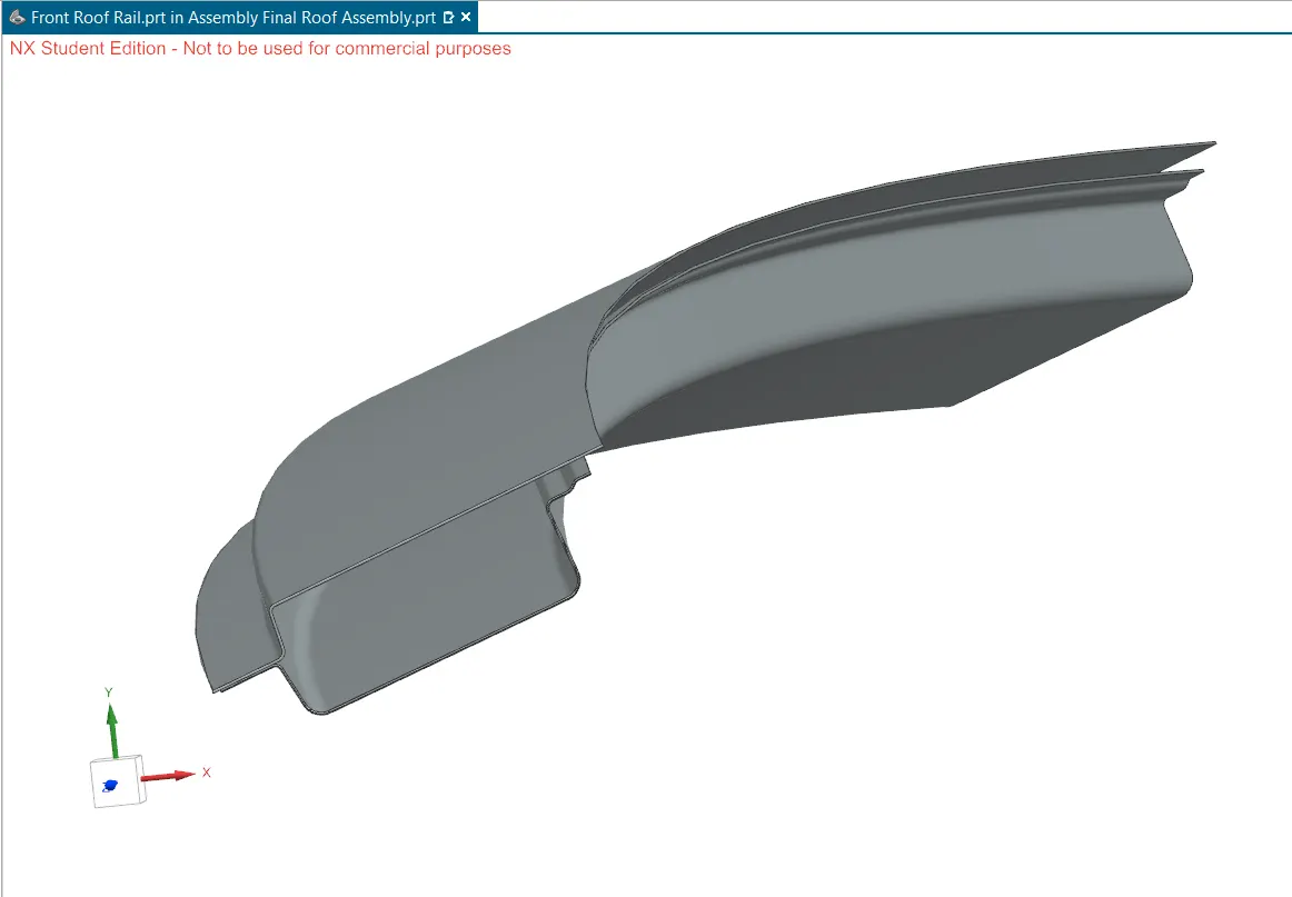
Fig 2. Front Roof Rail
Now after the Front Roof Rail the Rear is Created using the given Sketch with the appropriate dimensions and then the Sheet Part is Thicken with the 0.75mm.
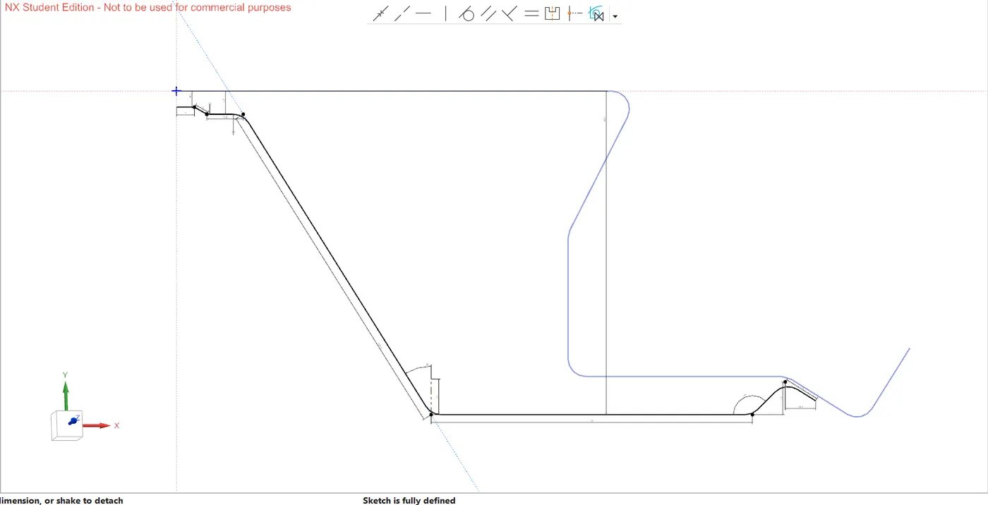
Fig 3. Sketch for Rear Roof Rail
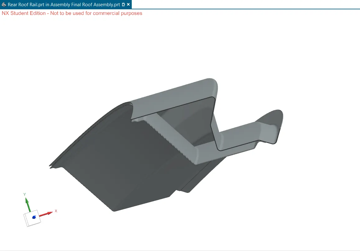
Fig 4. Rear Roof Rail
After the Rear Roof is done now lets move to the Roof Bow.
The Bow Roof is an important part which help the Outer Panel in increasing the strength because the Outer Panel is does not have enough strength to safe guard the passengers in safety. So the Bow Roof were added to increase the Strength. In this Challenge I have Created only 2 Bow Roofs. Then Bow Roof and the reinforcement Roof are in a same Dimension so I have created both in a same way but the Reinforcement Roof is created in the Center part of the Roof Outer Panel.
The Bow Roof is created using the given dimensions. Then the Thicken value is 0.75mm.
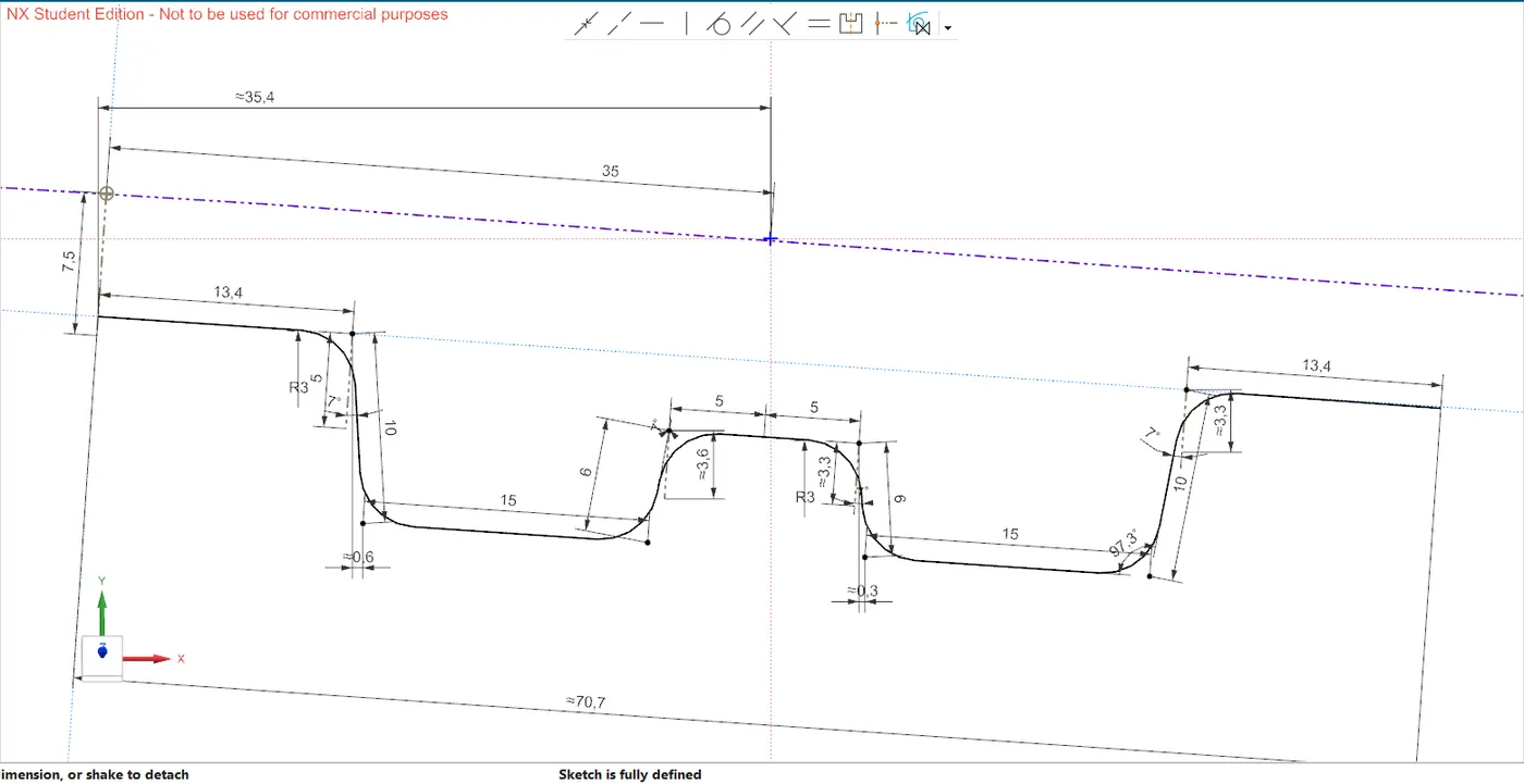
Fig 5. Sketch for Bow Roofs
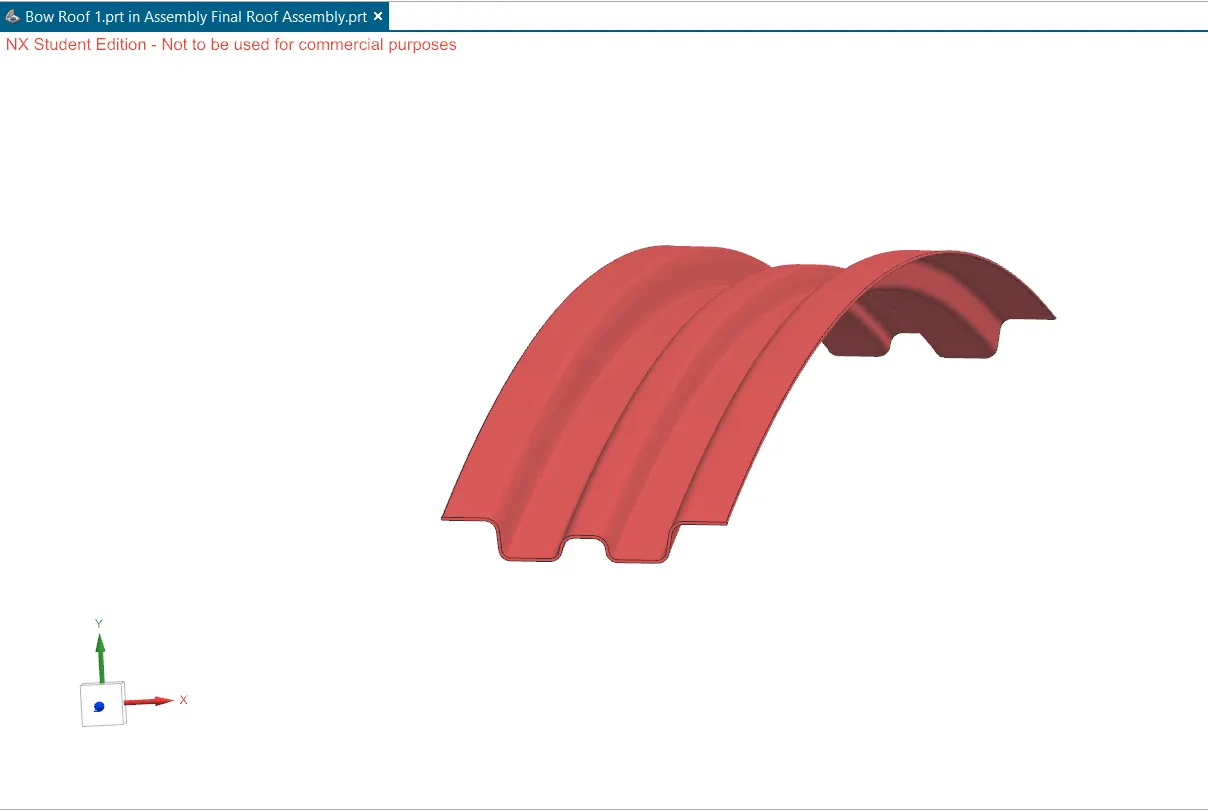
Fig 6. Bow Roof and Reinforcement Roof Part
Now after the parts are created the Draft Analysis is taken for the each Part.
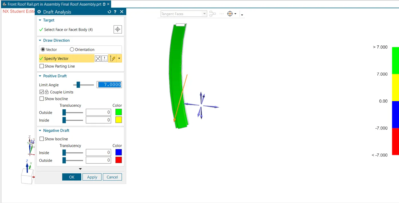
Fig 7. Draft Analysis for Front Roof Rail
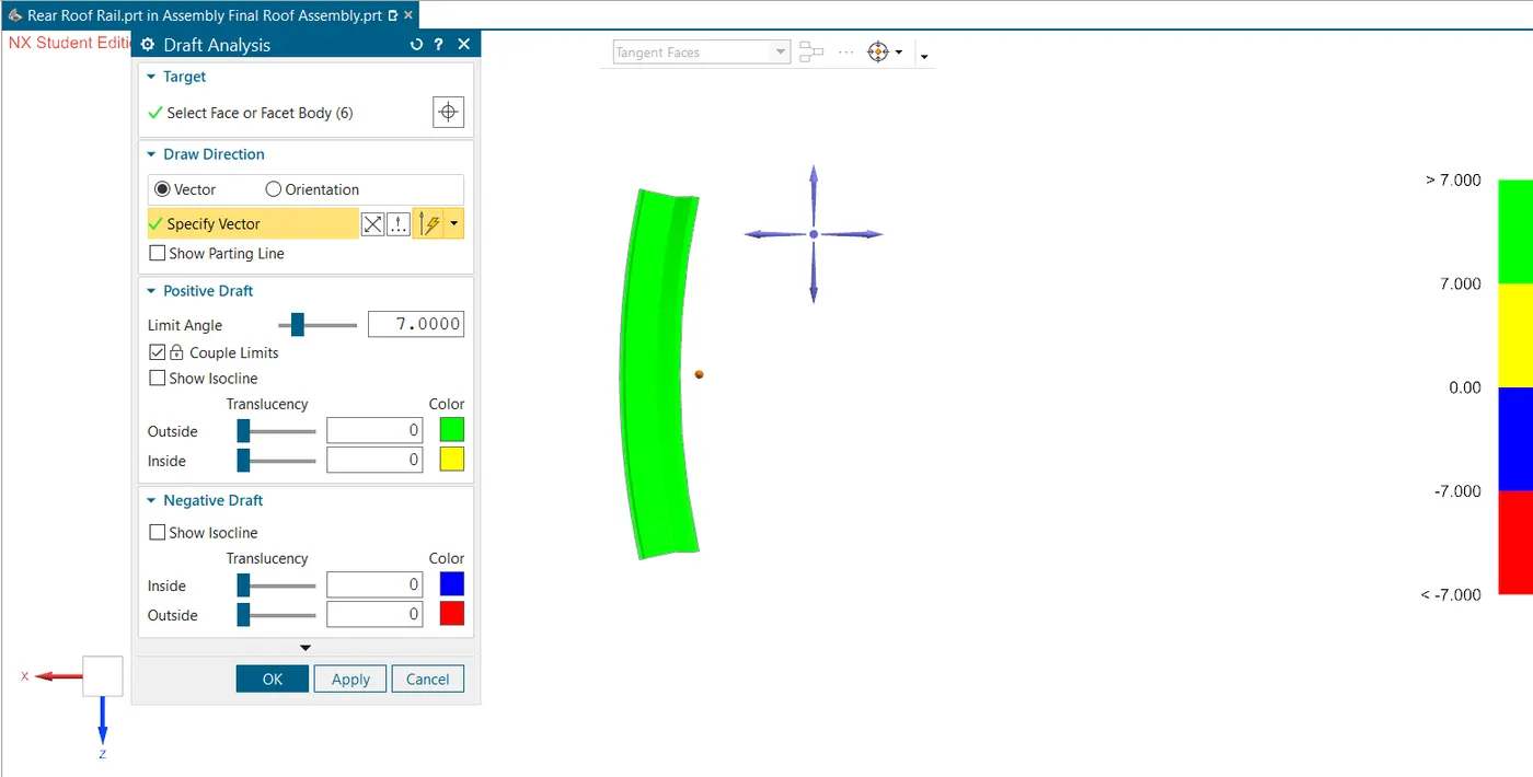
Fig 8. Draft Analysis for Rear Roof Rail
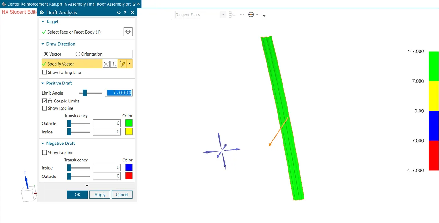
Fig 9. Draft Analysis for Reinforcement Roof Rail
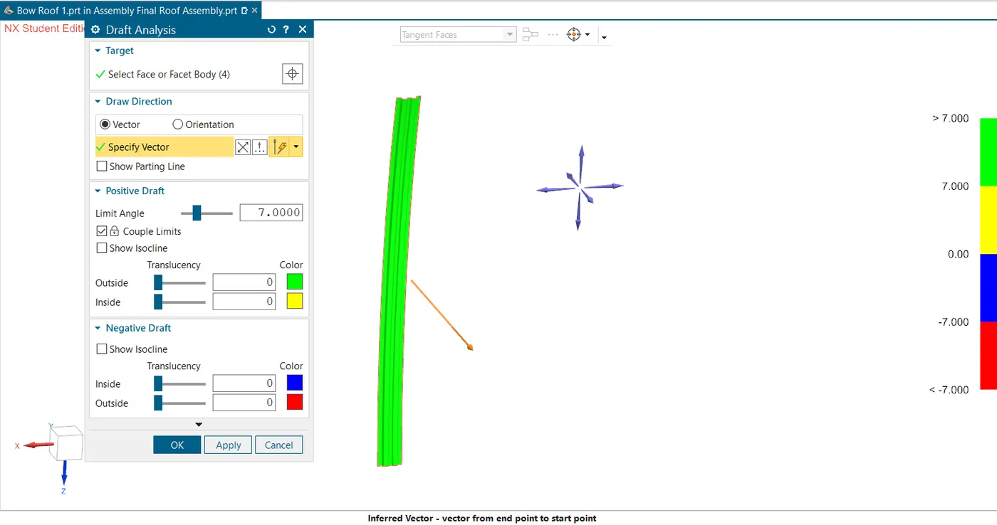
Fig 10. Draft Analysis for the Bow Roof 1
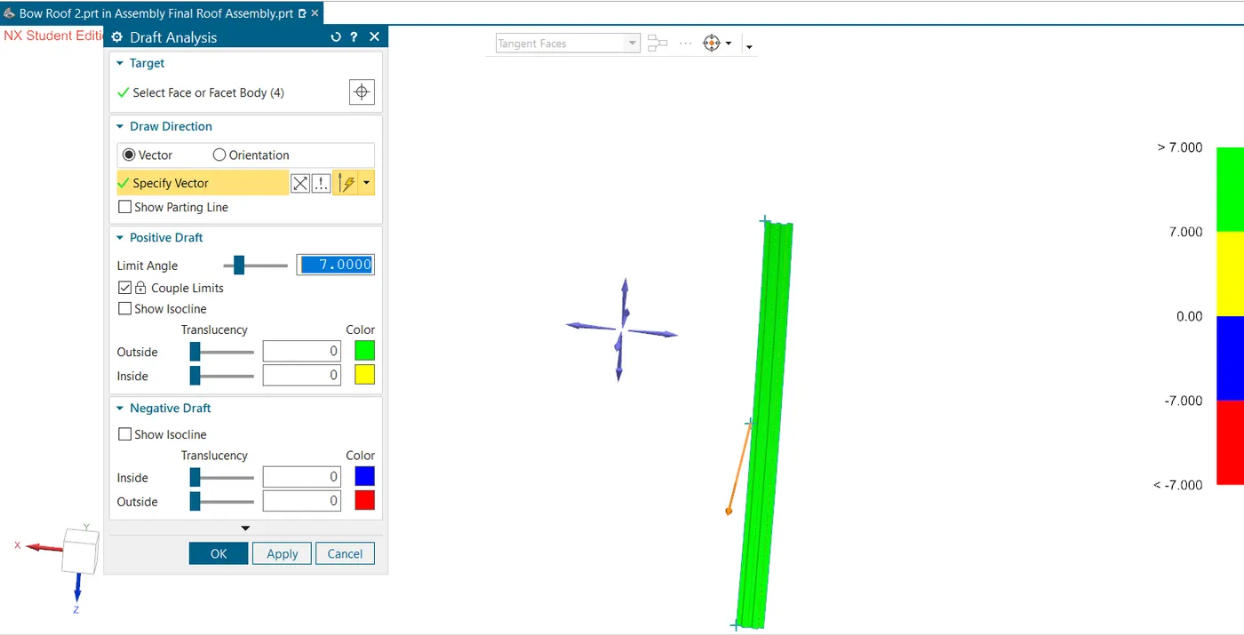
Fig 11. Draft Analysis for the Bow Roof 2
After the Draft Analysis is done the Section Inertia Analysis is done for the Bow Roofs and the Reinforcement Roof.
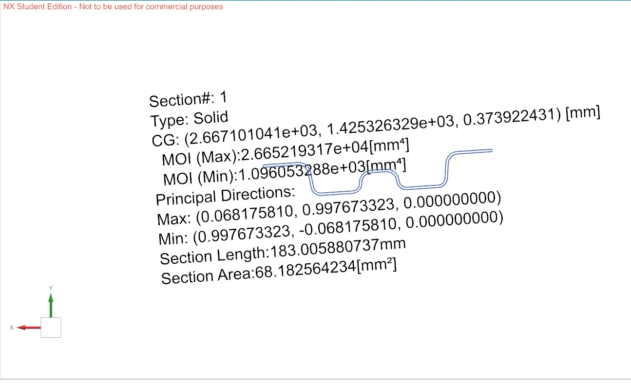
Fig 12. Bow Roof 1 Section Inertia Analysis
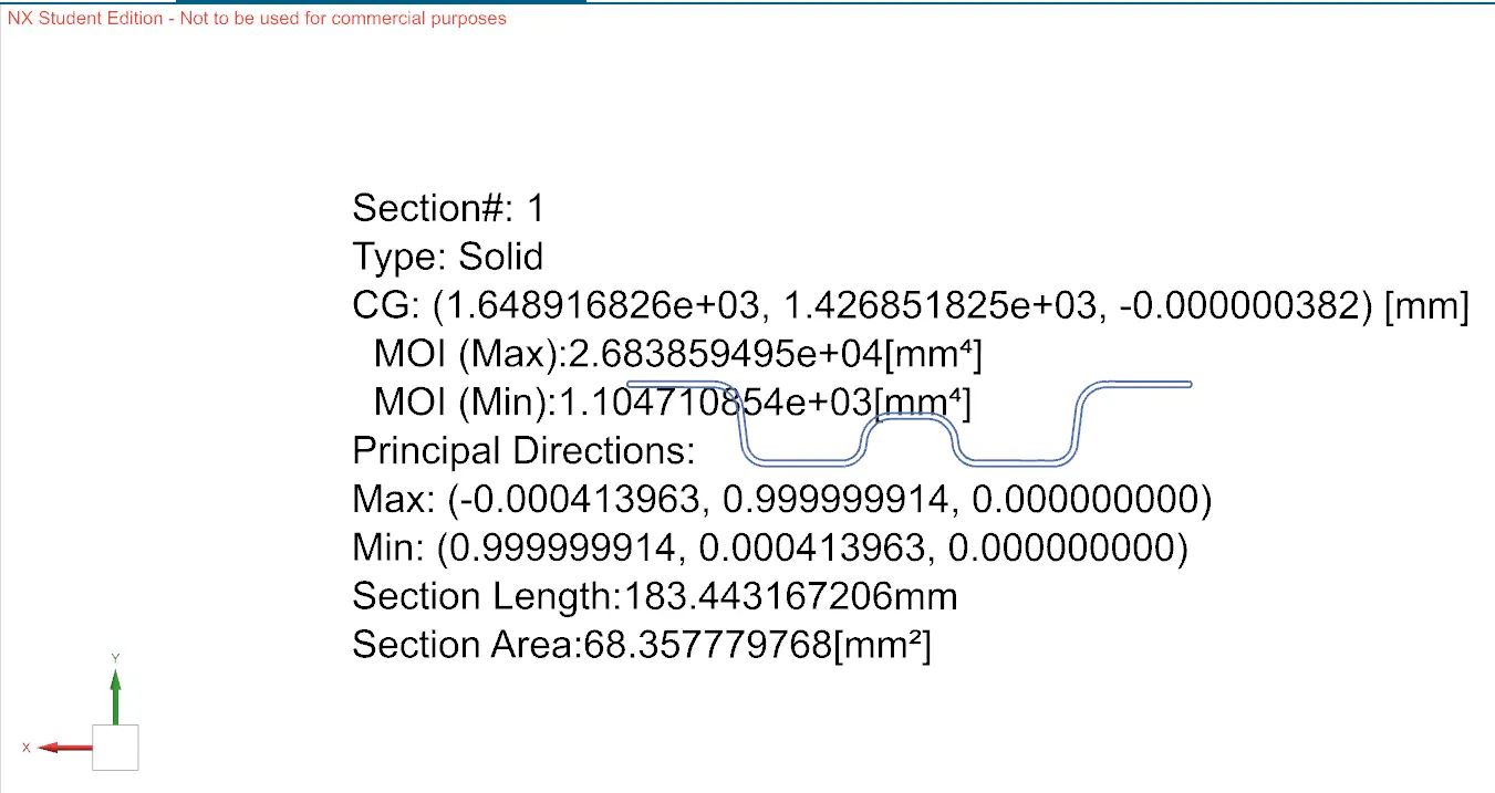
Fig 13. Bow Roof 2 Section Inertia Analysis
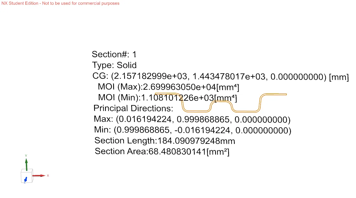
Fig 14. Center Reinforcement Section Inertia Analysis
The Section Analysis is taken to solve the Snowed Condition.
Now the Heat Distortion and the Snowed Condition were equated to find in the Constructed Roof Design.
First the Heat Distortion is find in the Constructed Roof Design.
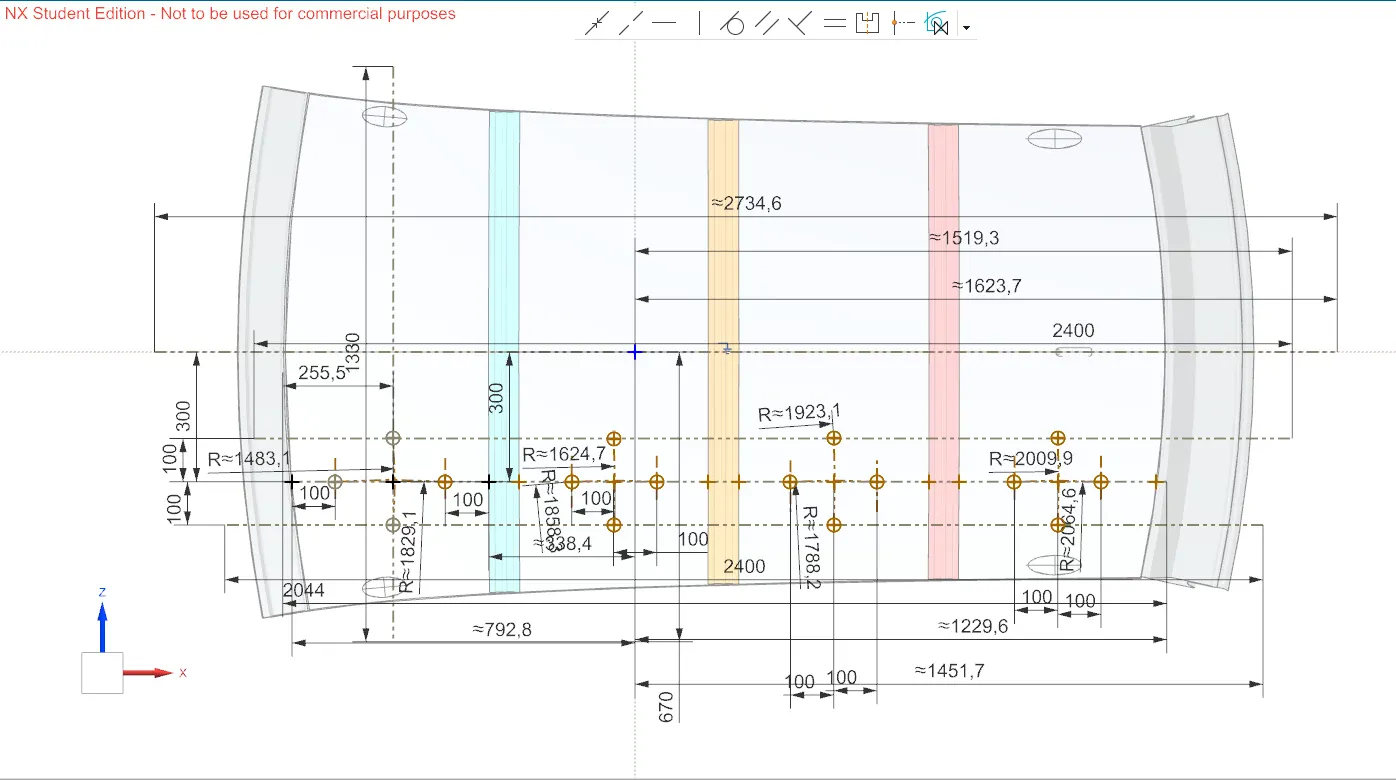
Fig 15. Heat Distortion Values
Heat distortion criteria:
Prediction formula=W=1.73×10⁻³×L+1.85×10⁻⁸×R2/t+1.10×10-3×l-2.68
The answer must be less or equal to 2.7 nor equal to 3.5
L= Roof length in X-direction
R= Roof curvature
R=2[(Rx × Ry)/(Rx +Ry)]
Rx= X curvature , Ry= Y curvature
t= Roof plate thickness (0.75 mm)
l= Bow roof span
| S.NO | BOWS | Rx | Ry | R | l | L | t | R2/t | W | OK/NG |
| 1 | FR & 2nd | 1483.1 | 1829.1 | 1638.028 | 454.4 | 2043.8 | 0.75 | 3577514.30 | 1.4218 | OK |
| 2 | 2nd & Centre | 1624.7 | 1858.3 | 1733.666 | 436.8 | 2043.8 | 0.75 | 4007463.73 | 2.0775 | OK |
| 3 | Centre & 1st | 1923.1 | 1788.2 | 1853.198 | 439.5 | 2043.8 | 0.75 | 4579123.76 | 2.1866 | OK |
| 4 | 1st & RESR | 2009.9 | 2064.6 | 2036.883 | 455.8 | 2043.8 | 0.75 | 5531856.47 | 1.4597 | OK |
W1 = 1.73×10-3×2043.8+1.85×10-8×3577514.30+1.10×10-3×454.4-2.68
= 1.4218
W2 = 1.73×10-3×2043.8+1.85×10-8×4007463.73+1.10×10-3×436.8-2.68
= 2.0775
W3 = 1.73×10-3×2043.8+1.85×10-8×4579123.76+1.10×10-3×439.5-2.68
= 2.1866
W4 = 1.73×10-3×2043.8+1.85×10-8×5531856.47+1.10×10-3×455.8-2.68
= 1.4597
From the above data the constructed Roof Design is good in Heat Distortion.
Now lets see the Snow Roof Criteria for the constructed Roof.
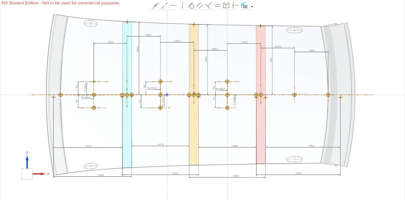
Fig 16. Snow Roof Values
SNOW ROOF CRITERIA:
Qr = ly × t2 / α×S×[(Rx + Ry)/2]2×108
Qr = 3.1
250≤S≤380
α = My × Ly2 × 10-12 , My=Y(Ly-Y)
t= Roof plate thickness(mm)
Ly = Distance between the front and rear roof RAILS on vehicle OY (mm)
Lx = Distance between the left and right end of the roof on the roof BOW(mm)
Y = Distance from FR roof Rail centre to roof Bow(mm)
S = Distance for which roof BOW bears divided load(mm)
ly = Geometric moment of inertia of roof BOW (Y cross section) (mm4)
Rx = Lateral direction curvature radius of roof panel Y cross section on roof BOW (mm)
Ry = Longitudinal direction curvature radius of roof panel X cross section on roof BOW (mm)
The above are values of each individual roof BOW
| S.N0 | BOW | ly | α | Lx | Ly | Y | S | Rx | Ry | t | Qr | OK/NG |
| 1 | FR & 2nd | 47.996 | 3.326 | 1108.79 | 2043.8 | 523.9 | 290.426 | 4585.5 | 8624.3 | 0.75 | 6.41 | OK |
| 2 | 2nd & Center | 50.391 | 2.936 | 1069.91 | 2043.8 | 437.8 | 291.247 | 3722.8 | 11874.4 | 0.75 | 5.45 | OK |
| 3 | Center & 1st | 51.1211 | 2.946 | 1048.12 | 2043.8 | 439.8 | 320.508 | 3670.7 | 12948.1 | 0.75 | 4.41 | OK |
| 4 | 1st & RR | - | 3.506 | - | 2043.8 | 569.4 | - | - | - | 0.75 | - | - |
Qr1= 47.996 ×(0.75)2 / 3.326×290.426×[(4585.5+ 8624.3)/2]2×108
= 6.41
Qr2 = 50.391 ×(0.75)2 / 2.936×291.247×[(3722.8 + 11874.4)/2]2×108
=5.45
Qr3 =51.1211× (0.75)2 / 2.946×320.508×[(3670.7+ 12948.1)/2]2×108
= 4.41
From the above given data the constructed Roof Design was good in Snow Roof Criteria.
So the Roof Design which is constructed is good in both the Heat Distortion and the Snow Roof Criteria.
Note: In the Observation Table the Bow Roof 1st and Bow Roof 2nd names were changed because in the Assembly I have changes the names from Bow Roof 2nd to Bow Roof 1st. So I adjusted the names in the Observation Table Bow Column.