Roof Design
AIM:
To Create the Roof Design with the assembly by developing the essential flanges for the required design
OBJECTIVES:
- The main objective of these project is to create the Roof sheet metal design using NX CAD with essential flanges for the roof, like the Front Roof rail, Rear Roof rail, Center Roof rail, and bow roof rail
- Do a curvature study on the roof perform calculations for heat distortion and snow load crietria to determine the position of the bow roofs.
- Finding the moment of inertia and section modulus for Bow roofs and Center roof rails
- And also finding the draft analysis of each part.
CONTENT:
- Introduction
- Roof Design
- Creation of Roof
- Testing of roof
- Calculation of Heat Distortion & Snow Load Crietria
- Draft analysis
INTRODUCTION:
An automobile roof, often known as a car top, is the piece of the vehicle that rests above the passenger compartment and protects the occupants from the sun, wind, rain, and other exterior factors. Because the first vehicles were created in an era of horse-drawn carriages, their roofs employed comparable materials and designs.
There were several types of roofs developed on automobiles in later periods. They are
- Convertible roofs
- roof modules
- hard tops
- T-tops
- Targa tops
- vinyl roof
Testing Of Roof:
MGA Research Corporation manufactures a quasi-static test equipment that is used to evaluate roof strength (Figure 3).The System comprises an upright assembly and a connected loadin head that may be adjusted to suit driver or passenger side testing at different ground heights and pitch angles between -5 and +5 degrees. The roll angle is set at 25 degrees for all time. The platen is moved by four Hydraulic actuators along two linear guides. A T-slot bet plate that is fastened to the test facility's floor supports the whole system.
Two HR A-36 — W10x88 I-beams are mounted on the bed plate perpendicular to the longitudinal axis of the platen. The vehicle, with attached rocker panel support system, is placed on these beams. The vehicle is adjusted so that The longitudinal centerline of platen is within 10 mm of the initial roof contact point.The yaw angle of the vehicle relative to the longitudinal axis of the platen is 0 ± 0.5 degrees.The midpoint of the platen’s forward edge is 254 ± 10 mm forward of the most forward point of the roof (including windshield trim if it overlaps the roof) lying on the vehicle’s longitudinal centerline.
The longitudinal centerline of platen is within 10 mm of the initial roof contact point.The yaw angle of the vehicle relative to the longitudinal axis of the platen is 0 ± 0.5 degrees.The midpoint of the platen’s forward edge is 254 ± 10 mm forward of the most forward point of the roof (including windshield trim if it overlaps the roof) lying on the vehicle’s longitudinal centerline.The vehicle's pitch angle compensates for any discrepancy between the nominal −5 degrees and the pitch angle of the platen, while also matching the on-road angle. The vehicle and platen pitch angles can deviate from their goals by a maximum of ± 0.5 degrees when combined. (For instance, the desired sill angle for the test would be −0.4 ± 0.5 degrees if the platen pitch angle was −5.2 degrees and the onroad vehicle pitch angle was −0.2 degrees.) Shims are placed between the W10x88 I-beams fastened to the bed plate and the rocker panel supports, if needed, to attain this angle.
Once the vehicle is positioned correctly, the rocker panel supports are clamped to the two perpendicular I beams, and the beams are marked to allow confirmation that the vehicle position is maintained during the test.For body-on-frame vehicles, the frame is supported to prevent the weight of the chassis from stressing the body at the body mounts. The roof is crushed to a minimum displacement of 127 mm at a nominal rate of 5 mm/second.Some tests are conducted to a greater displacement to collect additional strength data for research purposes. Force data are recorded from five load cells (Interface Inc., model 1220) attached to the loading platen.
Four linear variable displacement transducers (LVDTs) (MTS Temposonics type GH) incorporated into the hydraulic actuators provide the displacement data. The positions of the LVDTs and load cells on the loading platen are depicted in Figure 4.A National Instruments USB-6210 data gathering system is used to gather force and displacement data, which are then reported at 100 Hz. These statistics are based on a 2,000 Hz sampling rate, and the output data is produced at 100 Hz by averaging every 20 points.To confirm that the platen's roll angle and pitch angle (in relation to the vehicle's on-road pitch) were maintained at 25 ± 0.5 degrees and −5 ± 0.5 degrees, respectively, the displacement-time records from the LVDTs are compared.Still photos are used to record the pre- and post-crash states of every test vehicle. Additionally, the vehicle's location within the test fixture is noted. Testing with real-time video cameras is the foundation of motion picture photography.
ROOF DESIGN:
- The roof is the structure above the wind shield glass that has reinforcing to offer strength to the overall structure and to withstand overhead forces such as snow.
- In order to strengthen the roof, reinforcements such as front, central, and rear roof rails, as well as bow roofs, are added and connected to the flat roof surface using various joining techniques. A flat roof is very weak and unable to withstand forces such as snow.
Types of Reinforcements:
- Front Roof Rail
- Rear Roof Rail
- Center Roof Rail
- Bow Roof Rail 1
- Bow Roof Rail 2
Creation of the Roof:
1. Steps for the creation of the outer roof:
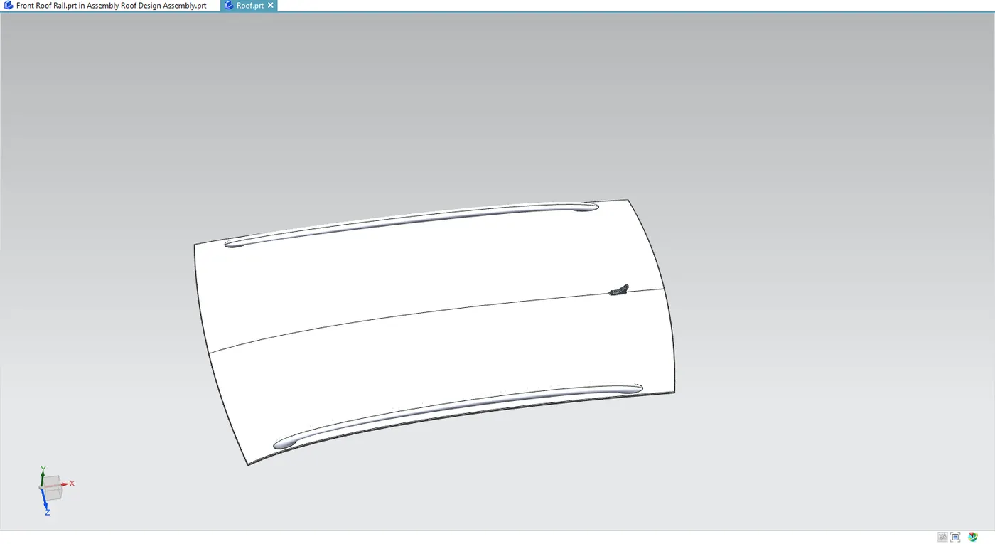
- Let's start the design with the styling surfaces mentioned in the question and load them into the NX CAD software, and it will look like the ones mentioned below.
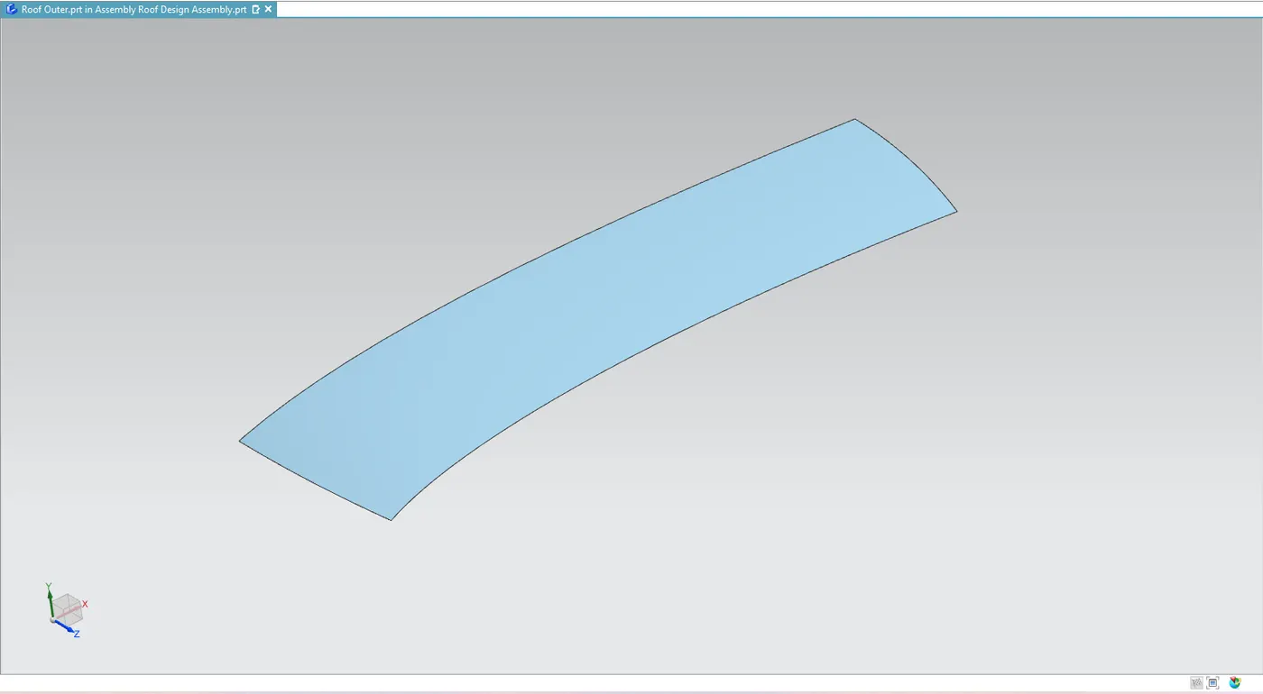
- Now Extract the half surface with using the Extract geometry option and it look like this condition were mentioned below
- Then start the design for the outer roof, which is given in the master section in the Front roof rail
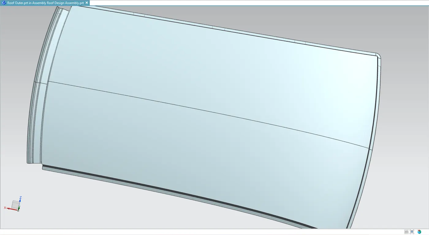
- Now we got half of the outer roof, mentioned the master section, and then mirrored the geometry with the help of Menu > Insert > Associative Copy > Mirror geometry.
- Then we joined two surface with the SEW option and we got the surface mentioned below
2. Steps for the creation of the front roof rail:
- First, create the sperate file in the assembly workbench for the Front Roof Rail Then, extract the surface with WAVE GEOMETRY LINKER option from the roof outer
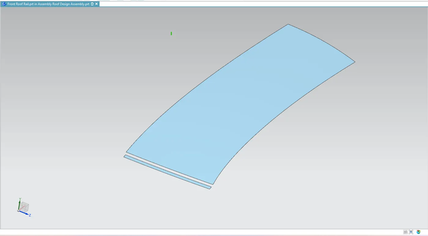
- Now Offset the surface with 32mm from the roof and again offset 1.5mm from the flange
- Then join the offset surface with the LAW EXTENSION command and Trim the surface with values were provided in the master section
- same process were being followed as per the Master Section, Then we got the front roof rail surface mention below.
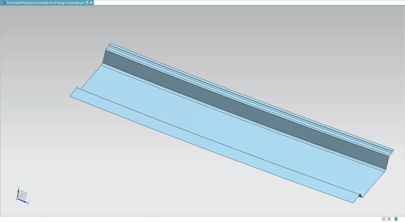
- Then create a Sketch for embossing the strengthened FRR by using the EMBOSS command and it will look as mentioned below
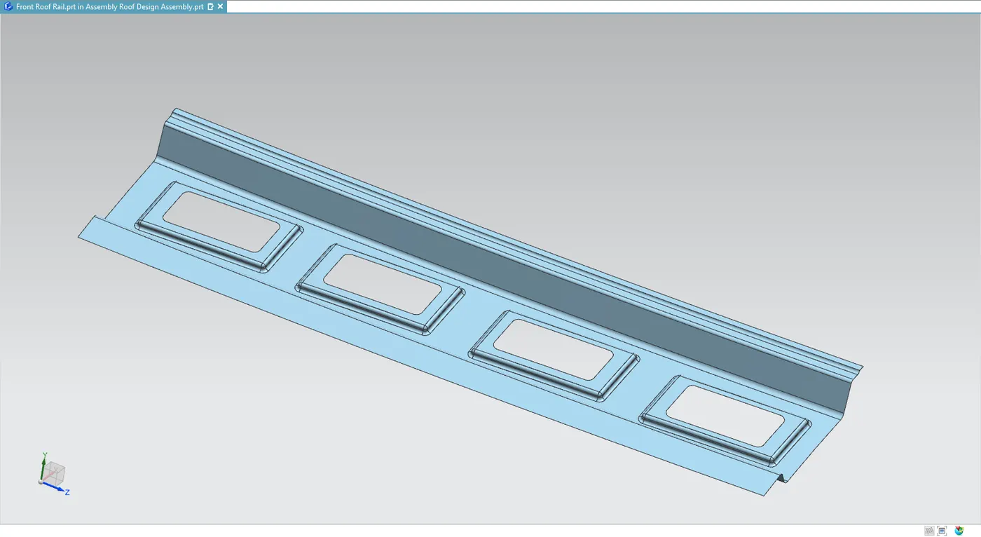
- Now we got half of the outer roof, mentioned the master section, and then mirrored the geometry with the help of Menu > Insert > Associative Copy > Mirror geometry.
- Then we joined two surface with the SEW option and we got the surface mentioned below
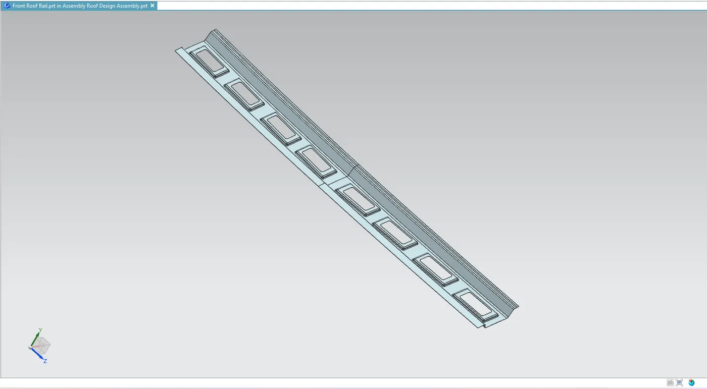
3. Steps for the creation of the rear roof rail:
- First, create the sperate file in the assembly workbench for the Rear Roof Rail, Then extract the surface with WAVE GEOMETRY LINKER option from the roof outer
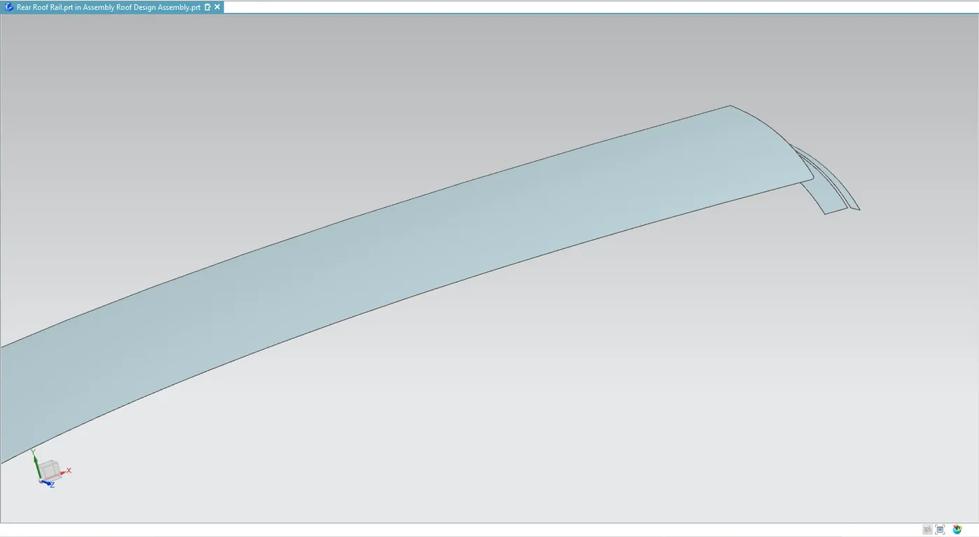
- Now Offset the surface with 10.7mm from the roof and again offset 1.5mm from the flange
- An Extent Sheet with Extent sheet command were mentioned in the master section
- Then join the offset surface with the LAW EXTENSION command and Trim the surface with values were provided in the master section
- same process were being followed as per the Master Section, Then we got the Rear roof rail surface mentioned below.
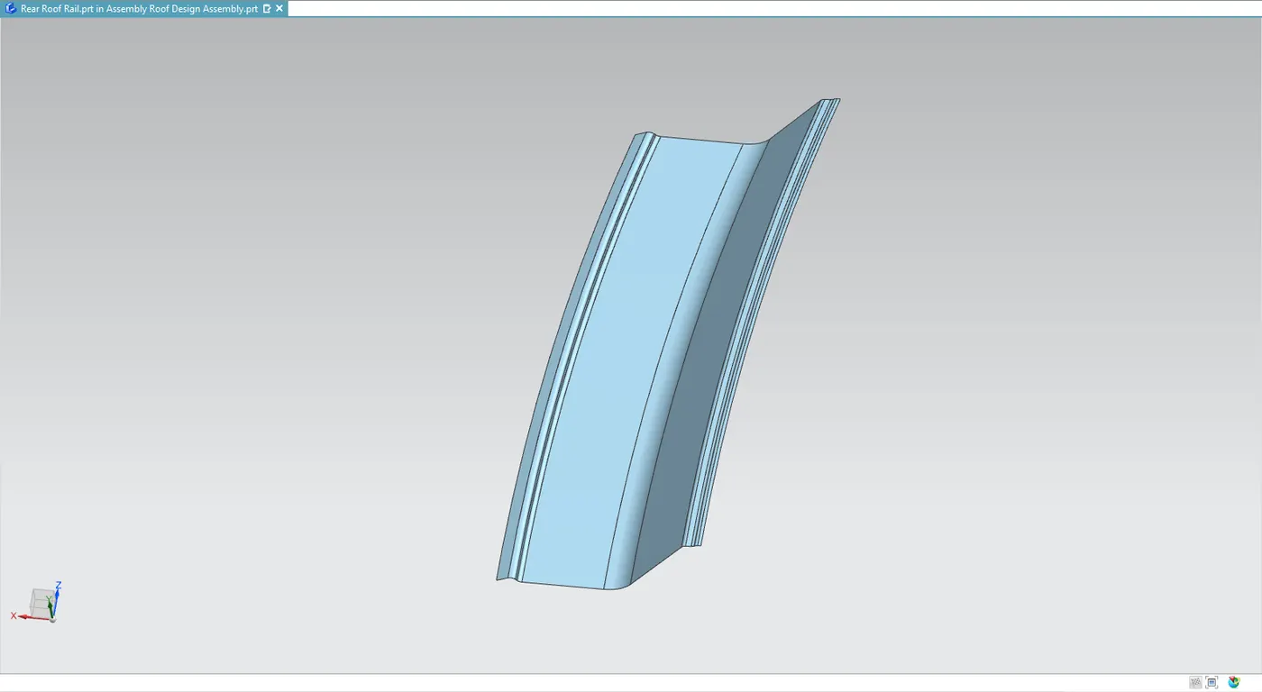
- Then create a Sketch for embossing the strengthened FRR by using the EMBOSS command and it will look as mentioned below
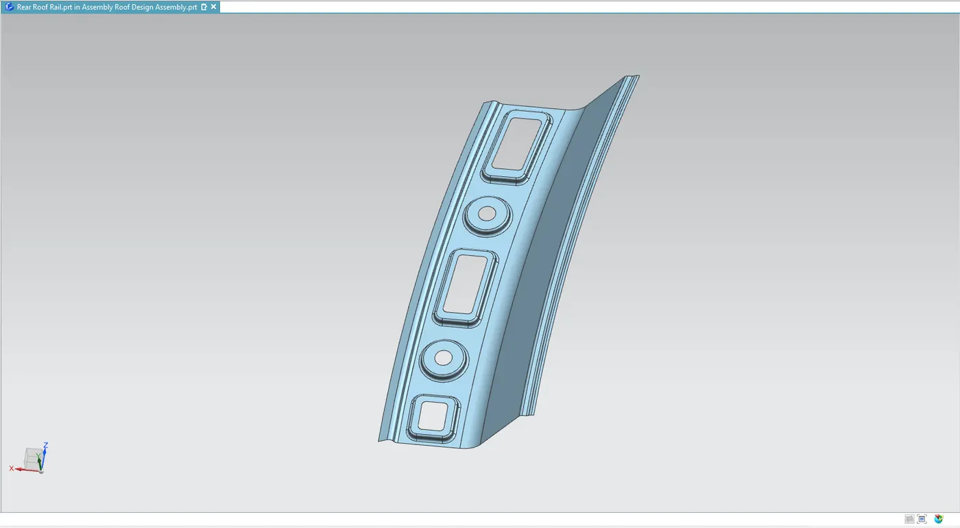
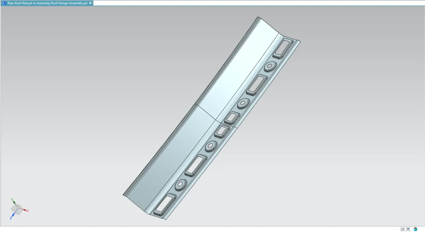
- Now we got half of the outer roof, mentioned the master section, and then mirrored the geometry with the help of Menu > Insert > Associative Copy > Mirror geometry.
- Then we joined two surface with the SEW option and we got the surface mentioned below
4. Steps for the creation of the Bow roof rails 1 and 2:
- First, create the sperate file in the assembly workbench for the Bow Roof Rail-1 & Bow Roof Rail-2, Then, extract the surface with WAVE GEOMETRY LINKER option from the outer roof.
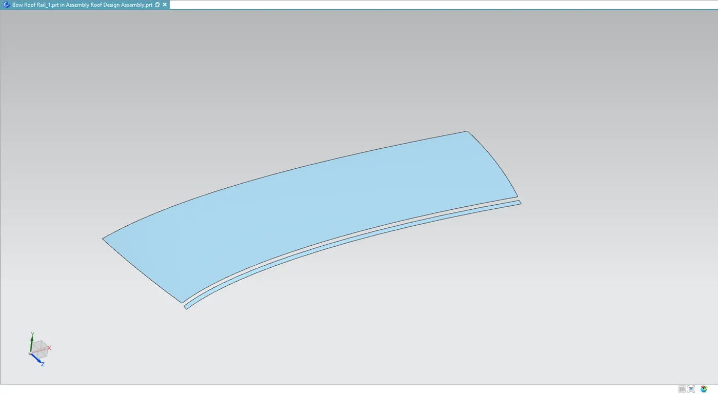
- Now Offset the surface with 6.5mm from the roof and again offset the assumptions taken from the master section
- Then join the offset surface with the LAW EXTENSION command and Trim the surface with values were provided in the master section
- The same process was being followed as per the Master Section, Then we got the Bow roof rail 1 and 2 surfaces mentioned below.
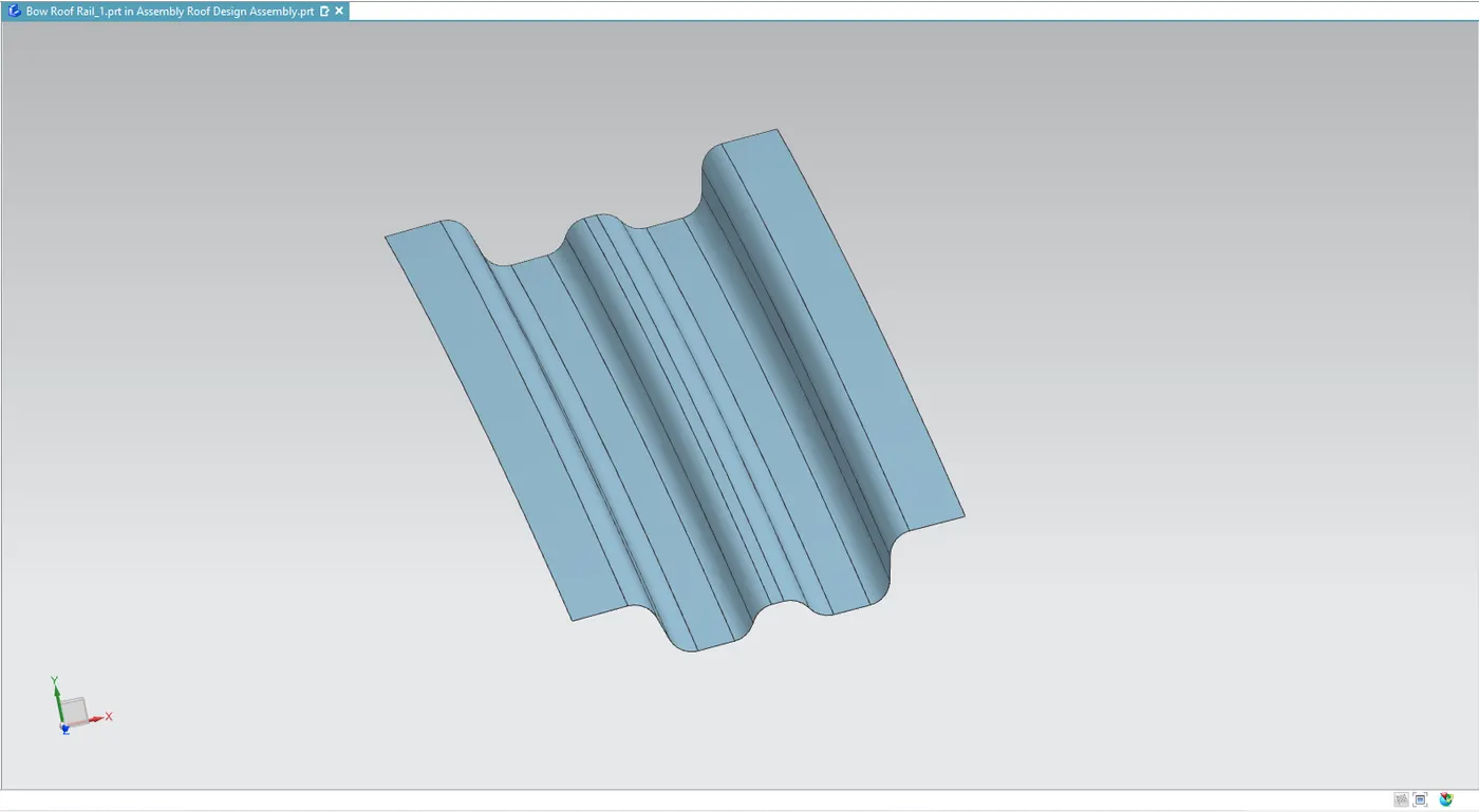
- Now Create the Ditch area that was mentioned in the video section and it look like it was mentioned in below
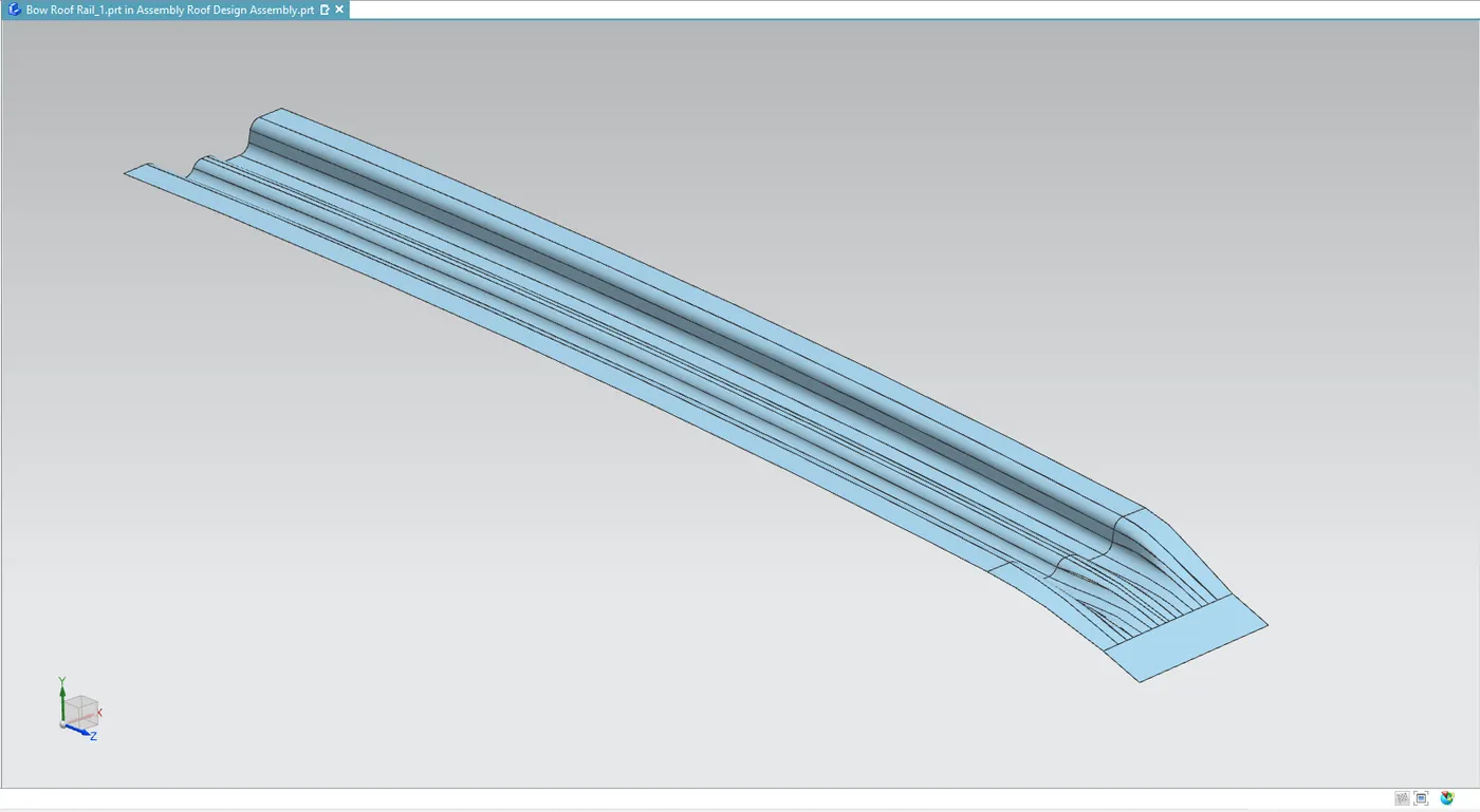
- Now we got half of the Bow Roof Rail-1&2, mentioned the master section, and then mirrored the geometry with the help of Menu > Insert > Associative Copy > Mirror geometry.
- Then we joined two surface with the SEW option and we got the surface mentioned below
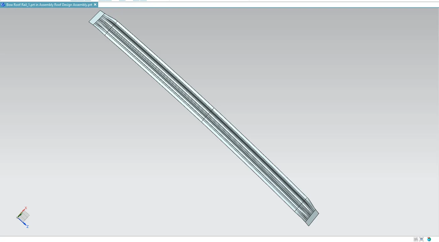
5. Steps for the creation of the center roof rails :
- First, create the sperate file in the assembly workbench for the Center Roof rail. Then, extract the surface with WAVE GEOMETRY LINKER option from the outer roof.
- Now Offset the surface with 6.5mm from the roof and again offset the assumptions taken from the master section
- Then join the offset surface with the LAW EXTENSION command and Trim the surface with values were provided in the master section
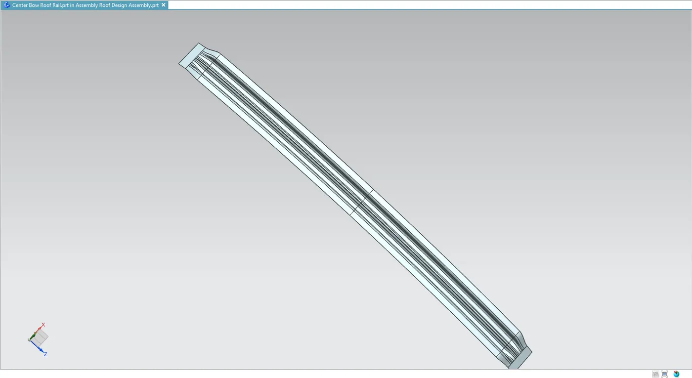
- The same process was being followed as per the Master Section, Then we got the center roof rail surface mentioned below.
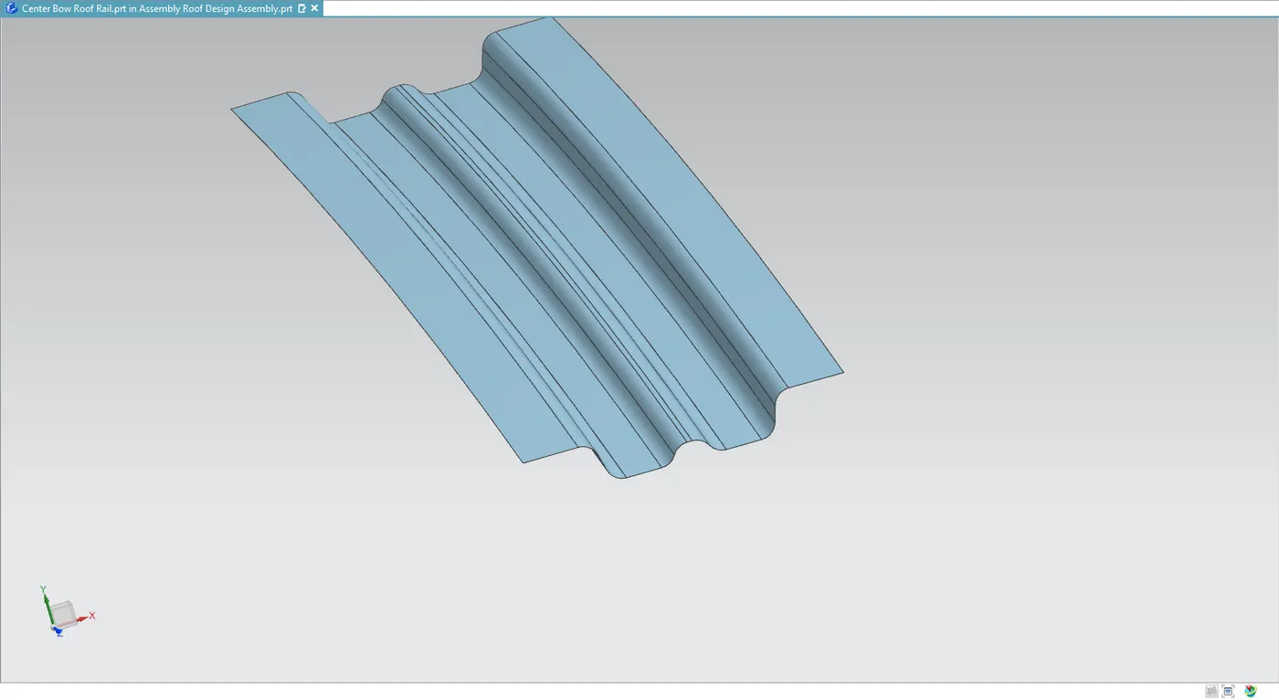
- Now Create the Ditch area that was mentioned in the video section and it should look like it was mentioned in below
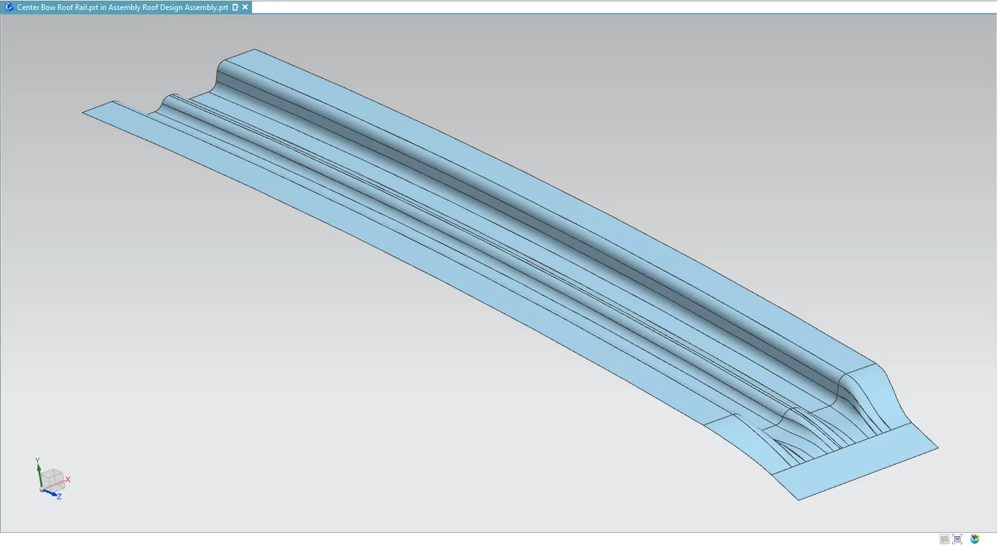
- Now we got half of the Center Roof Rail, mentioned the master section, and then mirrored the geometry with the help of Menu > Insert > Associative Copy > Mirror geometry.
- Then we joined two surface with the SEW option and we got the surface mentioned below
Calculation:
For our study, we are considering the following conditions for testing the roof:
- Heat Distorsion Calculations:
The use of sheet metal is significantly influenced by heat distortion research. Above a certain temperature, a material cannot be utilized for structural purposes; this is known as the heat distortion temperature. With a fixed load at a high temperature, this research is used to forecast the heat distortion temperature at which the material begins to soften. This study will anticipate the bow roof position, which helps to reinforce the roof, depending on the heat distortion temperature to prevent bending or damage to the roof.
Bow-Roof Prediction Formula
W = [1.73 x 10^(-3) x L] + [1.85 x 10^(-8) x (R^2)/t] + [ 1.10x10^(-3) x l] - 2.68
Where,
L = Roof Length in X-Direction[mm](Roof dimension in 0-Y)
R = Roof curvature; R = 2(Rx*Ry)/(Rx+Ry)
Rx = X curvature
Ry = Y curvature
t = Roof plate thickness [mm]
l = Bow Roof Span [mm]
Judgement Condition OK< 2.7
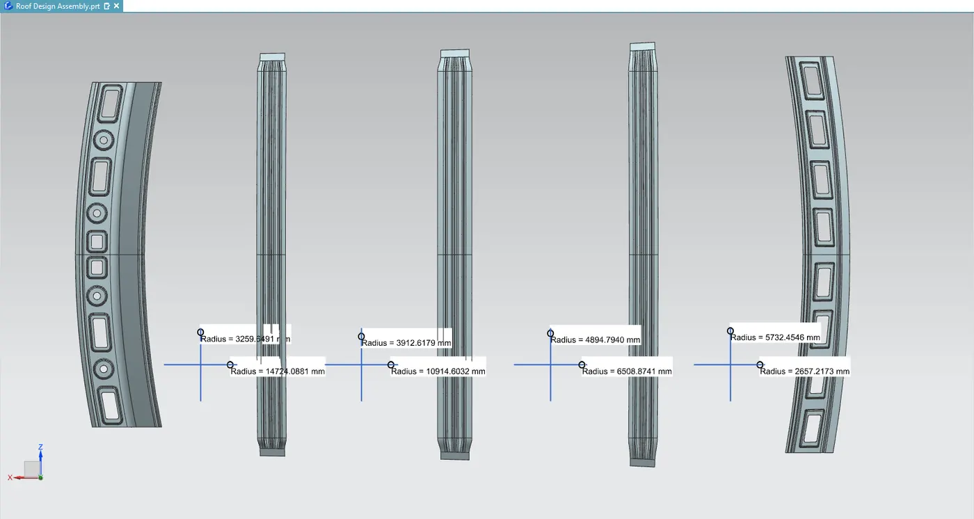
- For the aforementioned, we are able to record and compute as indicated below:

- We may infer from the above table that the bow roof locations fulfill the heat distortion criteria and are suitable for manufacture.
- Snow Load Criteria:
The purpose of this test is to determine the roof's behavior during a snowfall. Usually, the dent occurs because of the weight of the snow. However, the roof should be built so that it returns to its original position when the snow is removed. These are the fundamental prerequisites for the snow load criterion.
Qr = [Iy x t2] / [α x s x [(Rx + Ry)/2]2 x 10-8]
Note: The Qr value given over here is correct. There was a typo error in the formula given in the video.
Where,
α = My x Lx2 x 10-12 , My = Y(Ly-Y)
t = Roof plate thickness [mm]
Ly = Distance between the front and rear roof Rails on the Vehicle along with 0Y[mm]
Length of Roof panel with the center point between Roof rail Front /Rear as the front and rear reference point.
Lx = Distance between the Left and Right end of the roof on the Roof BOW [mm]
The width of the roof panel is exposed on the surface.
Y = Distance front Front Roof Rail to Roof BOW[mm]
s = Distance for which the roof roof bears a divided load (mm) s = L1/2 + L2/2
Iy = Geometrical moment of inertia of Roof BOW (Y cross-section )[mm4]
Rx = Lateral direction curvature radius of roof panel Y cross-section on Roof BOW [mm]
Roof panel curvature Radius of the Length Lx in Front view
Ry = Longitudinal Direction curvature radius of the Roof panel X cross-section on Roof BOW [mm]
Roof panel X curvature radius of length s in Side view
Judgment Condition Qr ≥ 3.1
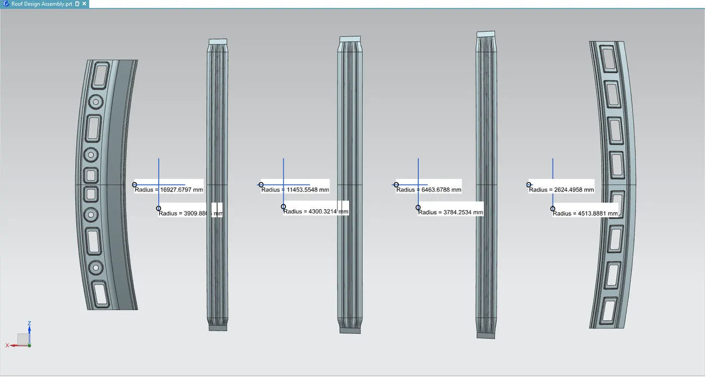
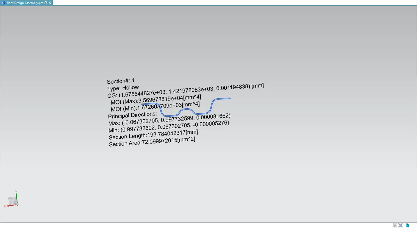
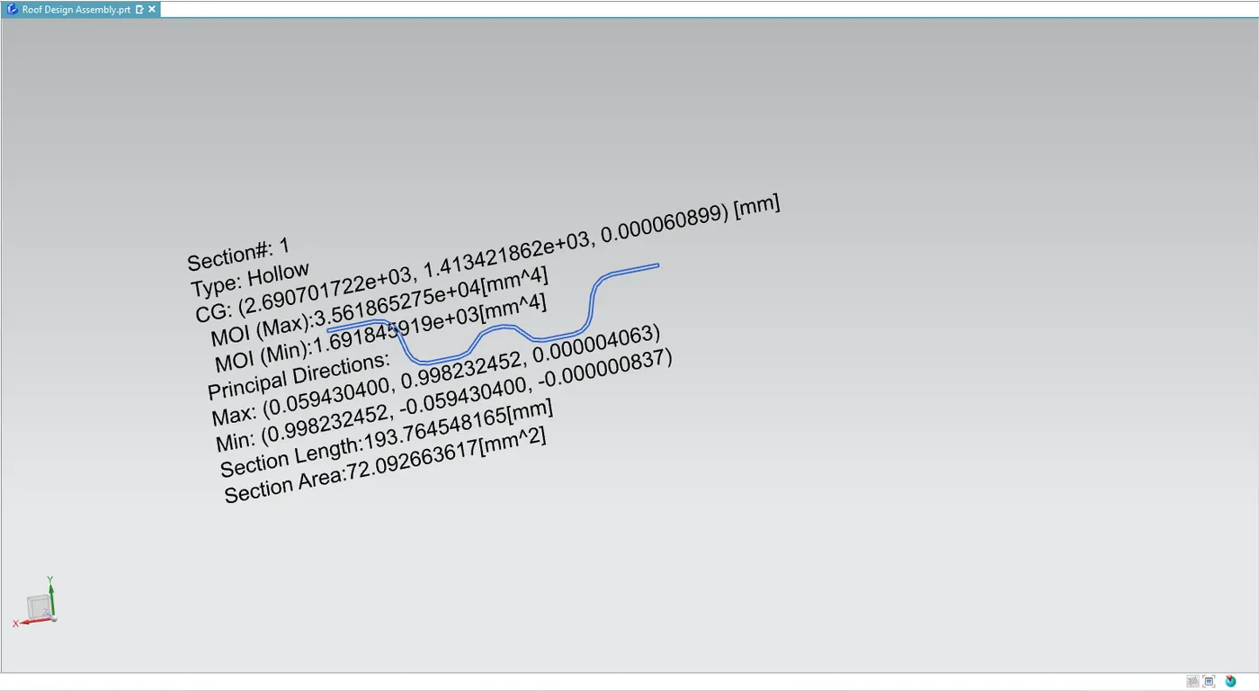
- Section analysis for the Geometrical moment of inertia of Roof BOW (Y cross-section )[mm4]
1. Bow Roof Rail-1 Section Analysis:
2. Bow Roof Rail 2 Section Analysis:
3. Center Rood Rail Section Analysis:

- For the aforementioned, we are able to record and compute as indicated below:

- We may infer from the above table that the bow roof locations fulfill the heat distortion criteria and are suitable for manufacture.
Draft Analysis for the Reinforcements:
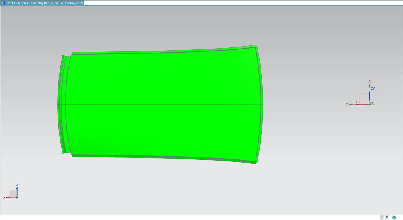
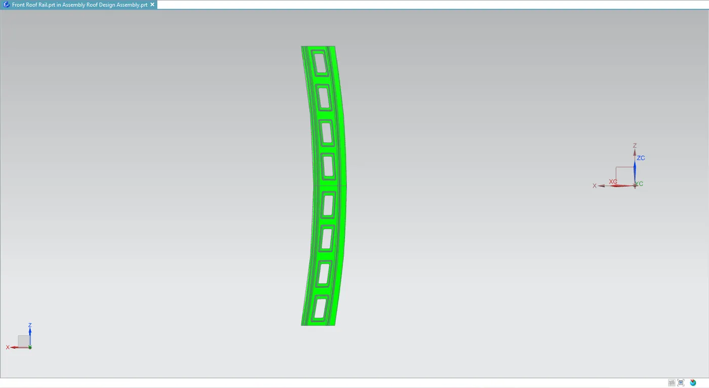
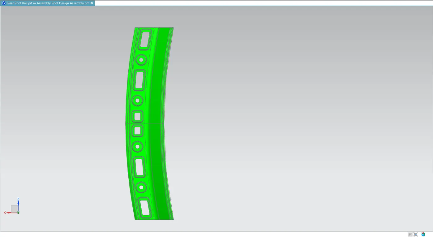
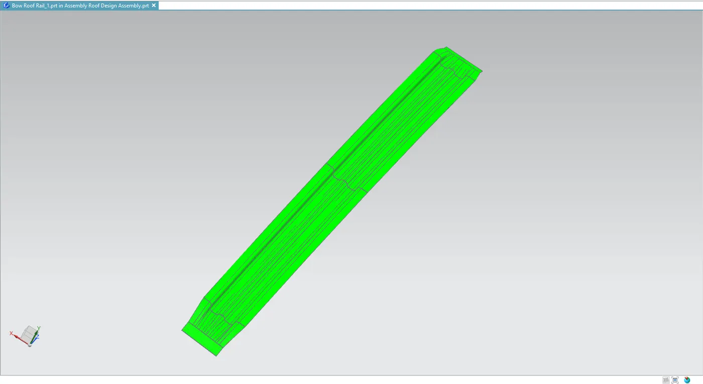
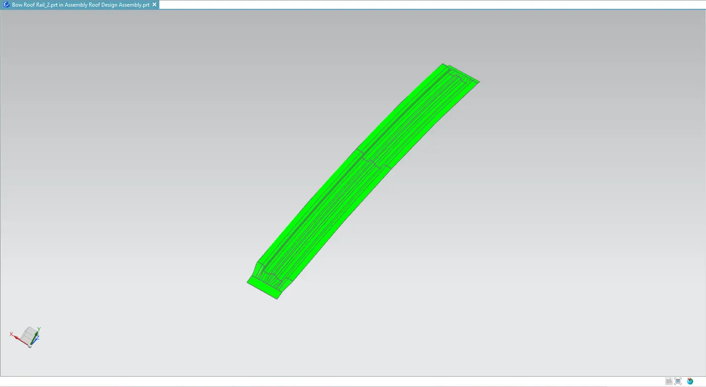
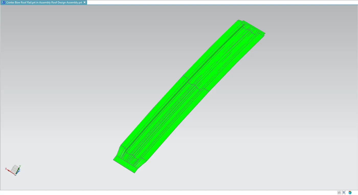
You may determine whether the portion you drafted will be simple to delete with the Draft Analysis command. The basis for this kind of analysis is color ranges that show the areas on the studied element where the deviation from the draft direction at any given time matches predetermined values.For analysis, a minimum draft angle of 70 is taken into account. Green color indicates that all of the components facing the tooling direction have a positive draft angle of at least 70 and have passed analysis.
1. Roof Outer:
2. Front Roof Rail:
3. Rear Roof Rail:
4. Bow Roof Rail-1:
5. Bow Roof Rail-2:
6. Center Roof Rail:
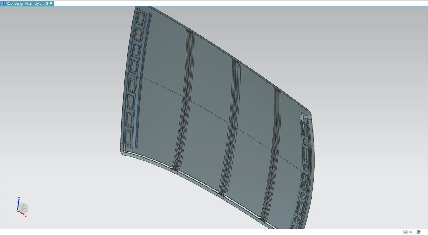
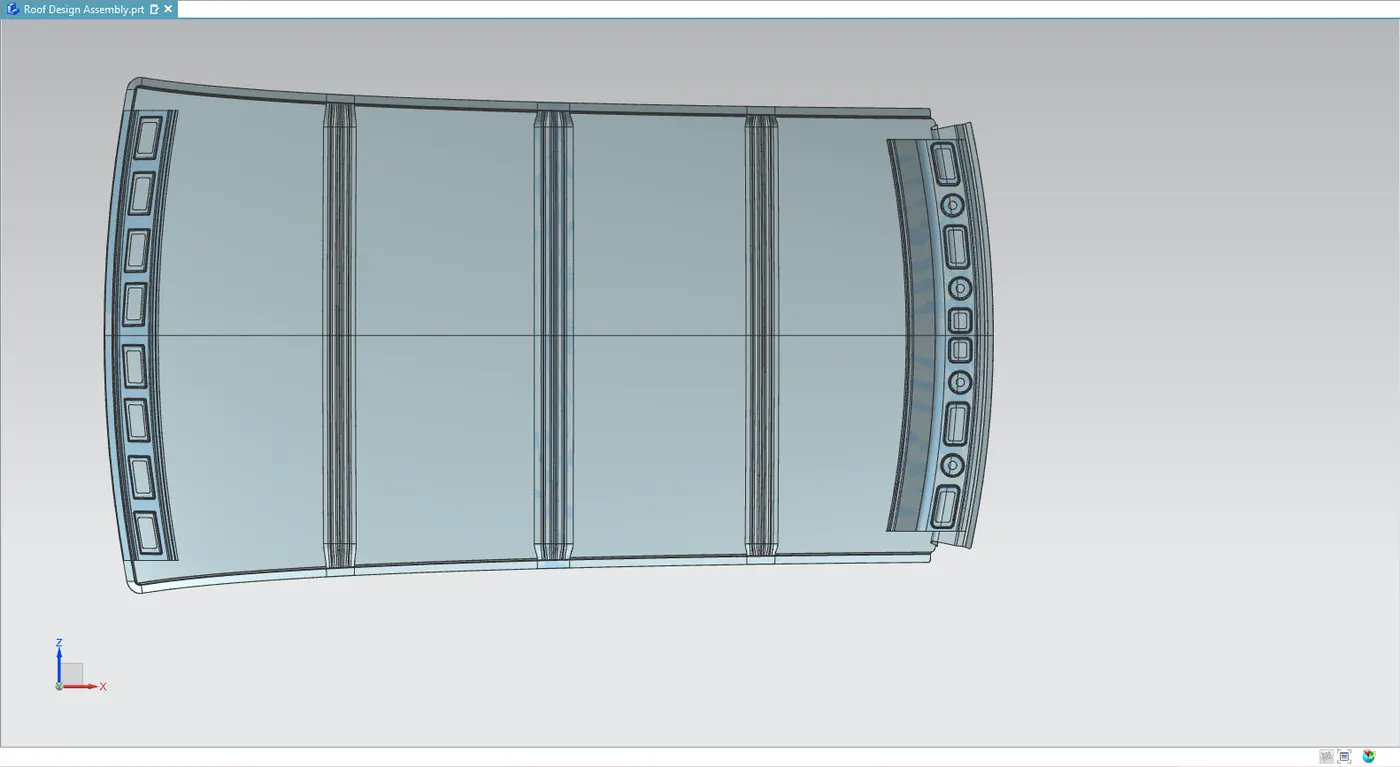
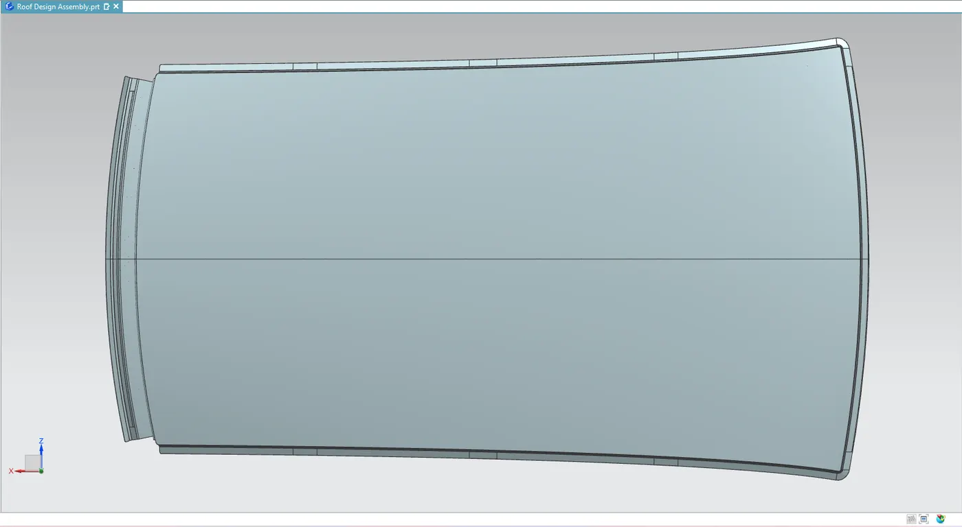
Different Orientations of Roof Design:
Conculsion:
As a result, we create the roof, front roof rails, center roof rails, and rear roof rails based on the Master Section drawing, do design analysis and moment of inertia calculations, and confirm that manufacturing is feasible.
Files:
Those file were uploaded in the name of the "Challenge 4 (Roof Design).zip" and images Calulation file also uploaded in the same folder