Roof Design
Roof Design
AIM:
To design the roof of a car adhering to the master section and design parameters.
INTRODUCTION:
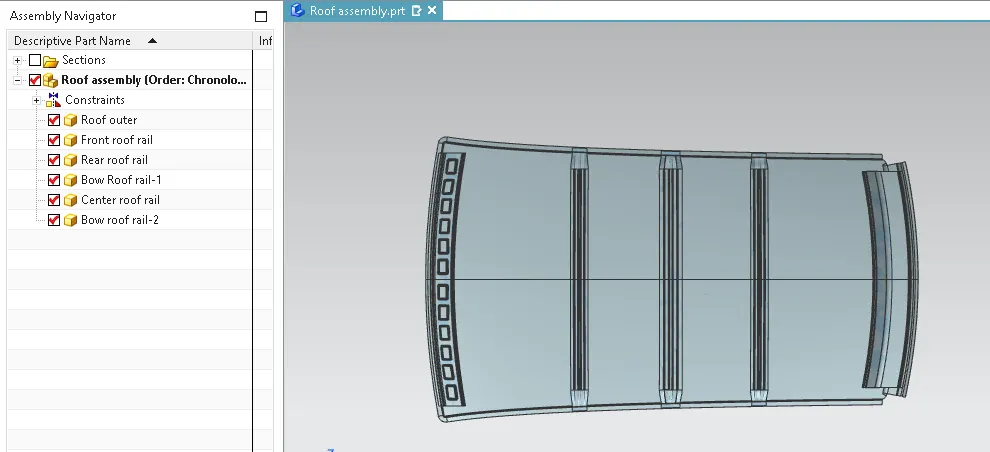
The roof of a car is a critical structural component, composed of several parts that collectively offer support and strength. The primary component is the roof panel, which is affixed to the Body in White (BIW) using front and rear roof rails. These roof rails, along with the actual roof sheet, support and reinforce the roof structure. The attachment between the roof panel and the BIW is achieved using sealants, ensuring a secure and durable connection. The design must accommodate various factors such as aerodynamic efficiency, structural integrity, and aesthetic considerations.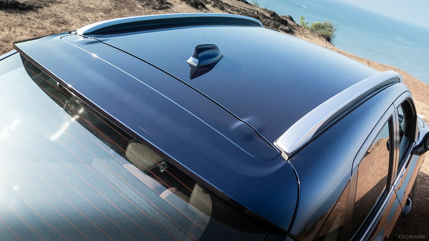
FRONT ROOF RAIL
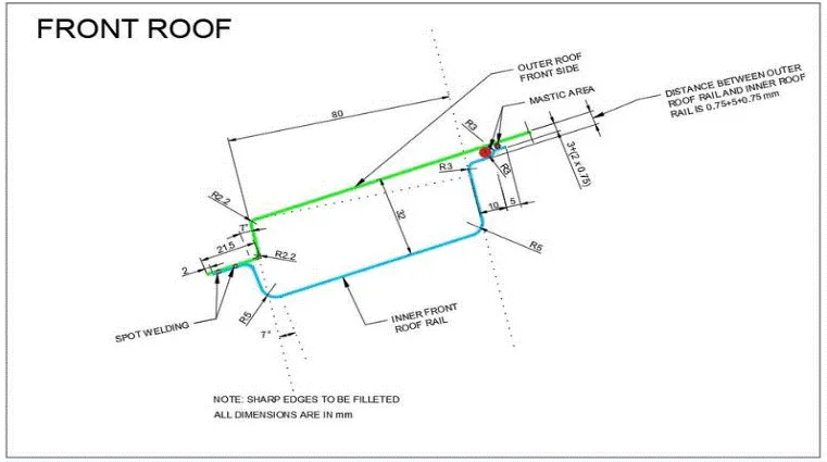
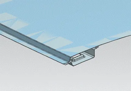
The front roof rail is a crucial structural element of a vehicle’s roof system, positioned along the front edge of the roof. It provides essential structural integrity, supporting the roof panel and contributing to the vehicle's overall rigidity. Beyond its foundational role, the front roof rail serves as a versatile platform for mounting various components, including the windshield header and roof-related accessories like sunroofs or roof racks. It also plays a key role in the sealing process, ensuring a secure connection between the roof panel and the vehicle body, and can influence the vehicle’s aerodynamics, enhancing overall efficiency.
REAR ROOF RAIL
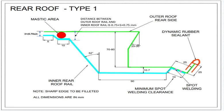
The rear roof rail is an essential structural element located along the rear edge of a vehicle's roof. Its primary function is to provide reinforcement and support to the rear portion of the roof structure, contributing to overall vehicle rigidity and occupant safety, particularly in the event of a rollover or collision. Similar to front and center roof rails, the rear roof rail serves as a mounting point for various accessories such as roof racks, bike carriers, or cargo boxes, adding versatility and utility to the vehicle.
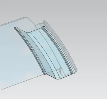
CENTER ROOF RAIL
The center roof rail is a vital structural component positioned along the centerline of a vehicle's roof. Serving as a key support structure, it reinforces the roof's strength and rigidity, crucial for safety in the event of a collision or rollover. Like other roof rails, the center roof rail also facilitates the attachment of various accessories such as roof racks, cargo carriers, or even mounting points for roof-mounted entertainment systems.
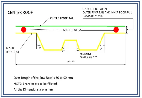
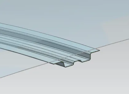
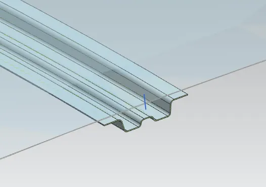
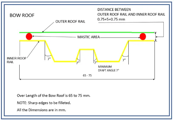
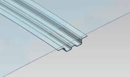
BOW ROOF RAILS-1
Bow roof rails are integral components in certain vehicle designs, contributing to both the structural integrity and functionality of the roof assembly, particularly in convertible or removable-top vehicles.
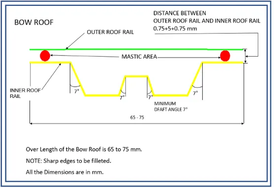
BOW ROOF RAILS-2
FINAL ASSEMBLY
HEAT LOAD CALCULATION
To calculate the heat load for a car, engineers use a combination of mathematical models, empirical data, and computer simulations. These methods help estimate the heat gain or loss under different operating conditions and enable the selection of HVAC systems with appropriate capacity to maintain comfortable interior temperatures efficiently.
Bow–Roof Prediction Formula
W = [1.73 x 10^(-3) x L] + [1.85 x 10^(-8) x (R^2)/t] + [ 1.10x10^(-3) x l] - 2.68
Where,
L = Roof Length in X-Direction[mm](Roof dimension in 0-Y)
R = Roof curvature
R = 2(Rx*Ry)/(Rx+Ry)
Rx = X curvature
Ry = Y curvature
t = Roof plate thickness [mm]
l = Bow Roof Span [mm]
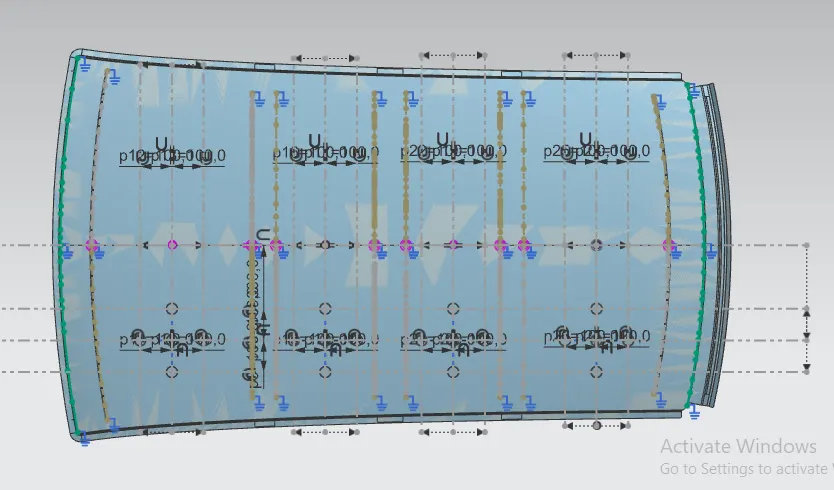
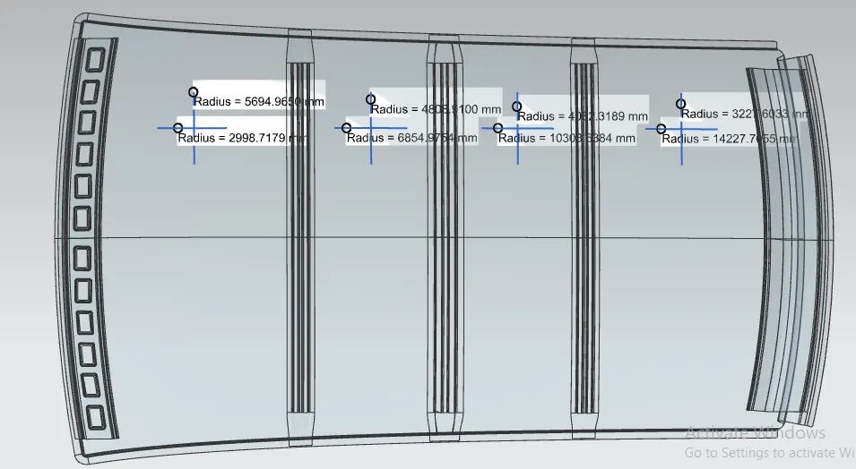
| SECTION |
RX(mm) |
RY(mm) | R(mm) | T(mm) | L(mm) | I(mm) | W | RESULT |
| FRR-BWR-1 | 5694.96 | 2998.71 | 3928.728 | 0.75 | 2031.49 | 505.6328 | 1.7713 | PASS |
| BWR1-CRR | 4808.91 | 6854.97 | 5652.481 | 0.75 | 2031.49 | 310.8524 | 1.9645 | PASS |
| CRR-BWR2 | 4032.31 | 10303.63 | 5796.261 | 0.75 | 2031.49 | 297.9012 | 1.9908 | PASS |
| BWR2-RRR | 3227.60 | 14227.70 | 5261.59098 | 0.75 | 2031.49 | 457.0648 | 2.0201 | PASS |
Judgment Condition
OK< 2>
SNOW LOAD CALCULATION
A snow load criteria study is indeed conducted to evaluate the durability of a roof in withstanding the weight of snowfall and returning to its original shape without permanent deformation once the load is removed.
Snow Load Prediction Formula
Qr = [Iy x t2] / [α x s x [(Rx + Ry)/2]2 x 10-8]
Note: The Qr value given over here is correct. There was a typo error in the formula given in the video.
Where,
α = My x Lx2 x 10-12 , My = Y(Ly-Y)
t = Roof plate thickness [mm]
Ly = Distance between the front and rear roof Rails on the Vehicle along with 0Y[mm]
Length of Roof panel with the center point between Roof rail Front /Rear as the front and rear reference point.
Lx = Distance between the Left and Right end of the roof on the Roof BOW [mm]
The width of the roof panel is exposed on the surface.
Y = Distance front Front Roof Rail to Roof BOW[mm]
s = Distance for which Roof BOW bears divided load [mm]
s = L1/2 + L2/2
Iy = Geometrical moment of inertia of Roof BOW (Y cross-section )[mm4]
Rx = Lateral direction curvature radius of roof panel Y cross-section on Roof BOW [mm]
Roof panel curvature Radius of the Length Lx in Front view
Ry = Longitudinal Direction curvature radius of the Roof panel X cross-section on Roof BOW [mm]
Roof panel X curvature radius of length s in Side view
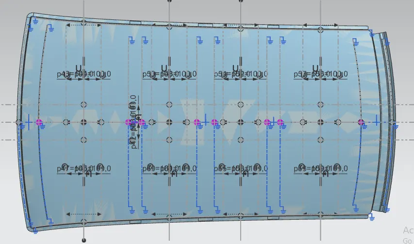
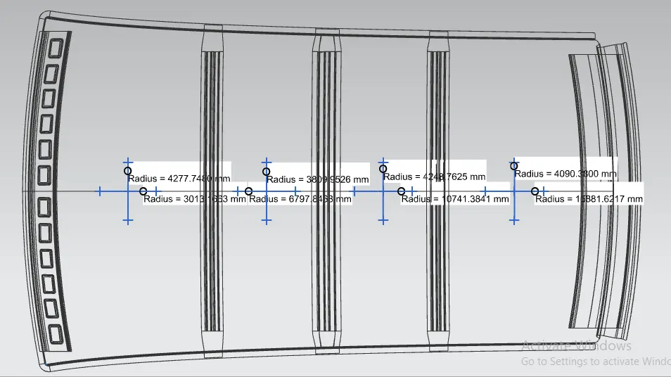
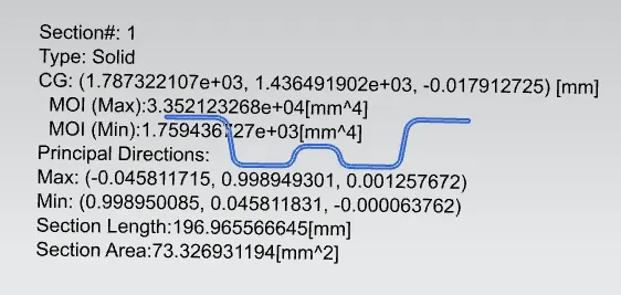
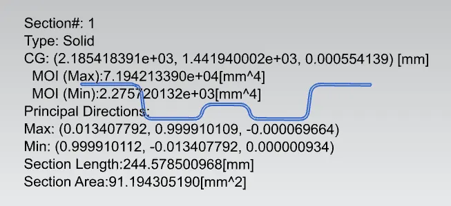
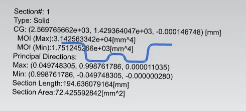
| SECTION | LX | LY | L1 | L2 | RX | RY | T | Y | S | MY | α | Qr | Result |
| FRR-BWR1 | 1127.7115 | 1966.3219 | 600.9166 | 398.4734 | 4090.3800 | 15881.6217 | 0.75 | 600.9166 | 499.695 | 826494.71049 | 1.04345 | 3.67346 | PASS |
| BWR1-CRR | 1080.8204 | 1966.3219 | 398.4734 | 384.5505 | 4248.7625 | 10741.3841 | 0.75 | 999.3882 | 391.5119 | 966342.12996 | 1.128854 | 5.15592 | PASS |
| CRR-BWR1 | 1059.1259 | 1966.3219 | 384.5505 | 582.3832 | 3809.9526 | 6797.8468 | 0.75 | 1338.9387 | 483.466 | 846027.6462 | 0.942299 | 7.6864 | PASS |
Judgment Condition
Qr ≥ 3.1
250 ≤ s ≤ 380
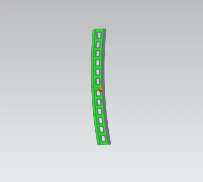
DRAFT ANALYSIS
1.DRAFT ANALYSIS OF FRONT ROOF RAIL
2.DRAFT ANALYSIS OF CENTER ROOF RAIL
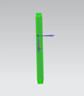
3.DRAFT ANALYSIS OF BOW ROOF RAILS-1

.4.DRAFT ANALYSIS OF BOW ROOF RAILS-2
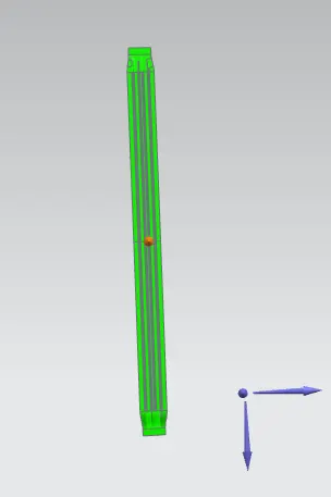
5.DRAFT ANALYSIS OF REAR ROOF RAIL
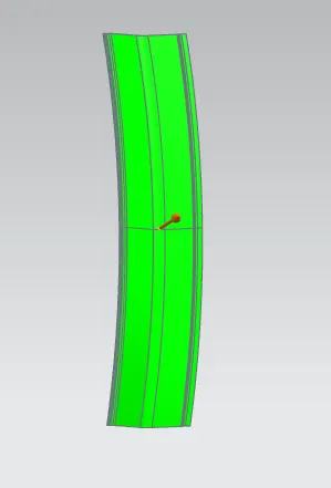
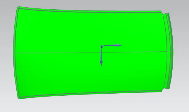
6.DRAFT ANALYSIS OF ROOF OUTER
CONCLUSION
The design of the roof was successfully completed in accordance with the given master sections. Additionally, heat load and snow load calculations were performed, ensuring that the roof meets all necessary performance and safety standards. The design process effectively addressed structural integrity, functionality, and environmental considerations, culminating in a robust and reliable roof system.