Roof Design
Aim:
<!-- [if !supportLists]-->· <!--[endif]-->To design a Roof Assembly by developing essential flanges for the outer roof and its reinforcements using the given Roof styling surface.
<!-- [if !supportLists]-->· <!--[endif]-->Perform Heat Distortion and Snow Load calculations (i.e., carrying out Curvature study or Bow Roof position justification) for the Roof.
Theory:
The following parameters we need to consider while designing a Roof:
<!-- [if !supportLists]-->· <!--[endif]-->Design requirements for the Roof and its components: -
<!-- [if !supportLists]-->· <!--[endif]-->Functional requirements
<!-- [if !supportLists]-->· <!--[endif]-->Types of Roofs and their functionality.
<!-- [if !supportLists]-->· <!--[endif]-->Roll-over test regulations and requirements.
<!-- [if !supportLists]-->· <!--[endif]-->Identification method to increase the strength of the Roof (Roof Bead).
<!-- [if !supportLists]-->· <!--[endif]-->Material identification techniques.
<!-- [if !supportLists]-->· <!--[endif]-->Joining techniques like Mastic, Brazing and Welding.
<!-- [if !supportLists]-->· <!--[endif]-->Heat Distortion and Snow Load calculations for determining the position of the BOW roofs.
Introduction: -
<!-- [if !supportLists]-->· <!--[endif]-->A Roof is an assembly of components consisting of Outer Panel and its reinforcement i.e., Front Roof Rail (FRR), Rear Roof Rail (RRR), Bow Roof Rails (depending upon the car body type).
<!-- [if !supportLists]-->· <!--[endif]-->All the specifications pertaining to a part and its constituents (i.e., material specifications, thickness, method of manufacturing, etc) is mentioned in a Design Concept Sheet (DCS).
Design considerations of a Roof: -
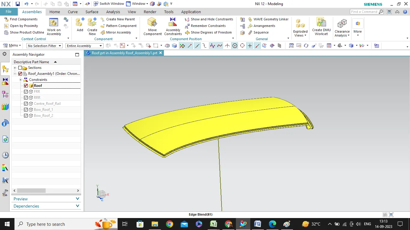
<!-- [if !supportLists]-->· While designing a Roof, a styling/edge point will be given, and from this point all the other roof dimensions will be generated like Ditch Area, flanges by considering the Deep Drawing directions.
<!-- [if !supportLists]-->· <!--[endif]-->Minimum most requirements are maintained for each value allotted to the features in order to maximize the Front Visibility Criteria.
Designing of Front Roof Rail (FRR): -
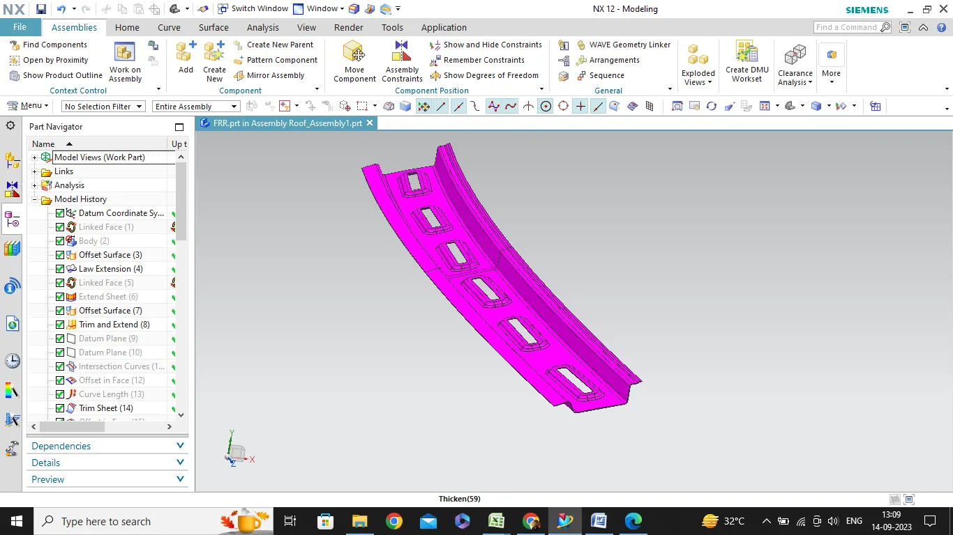
<!-- [if !supportLists]-->· <!--[endif]-->FRR is also designed by taking the reference of a styling/edge point on the Roof outer panel, and all the technical details like the visibility criteria line, head room clearance (HRC), deep drawing situations are considered while designing.
<!-- [if !supportLists]-->· <!--[endif]-->Provisions are given to accommodate the Mastics, Spot Welds which eventually increases the strength of the Roof.
<!-- [if !supportLists]-->· <!--[endif]-->In our case, we’re manufacturing the Roof using the Body Side OTR scrap.
Designing of Rear Roof (RRR): -
<!-- [if gte vml 1]>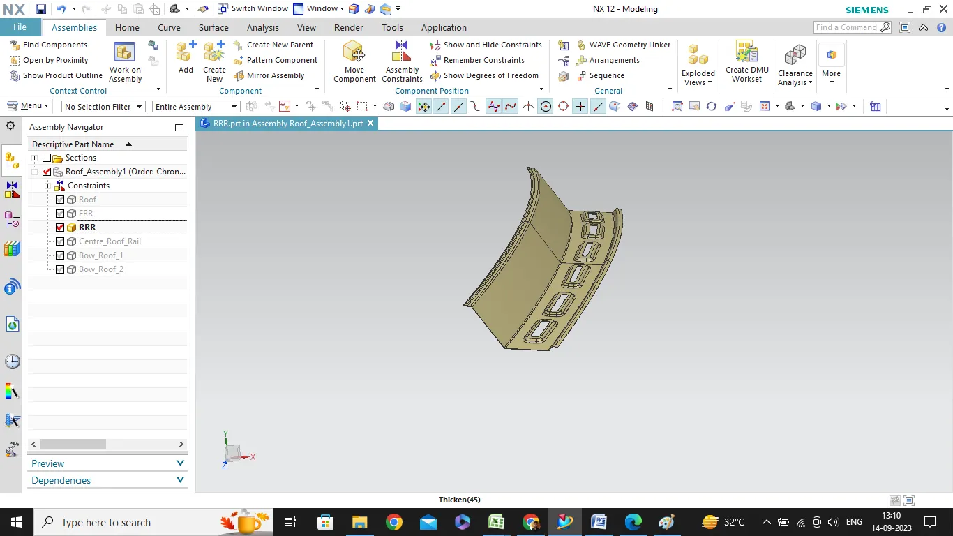 <!--[endif]-->
<!-- [if !supportLists]-->· <!--[endif]-->Rear Roof Rail (RRR) is also designed by considering the headroom clearance, rear visibility criteria among some other factors as per the Design Concept Sheet and the Master Section given.
<!-- [if !supportLists]-->· <!--[endif]-->A typical flange is designed at the rearmost end to join the RRR with the Backdoor.
Reinforcement Roof Centre/ Centre Bow Roof: -
<!-- [if gte vml 1]>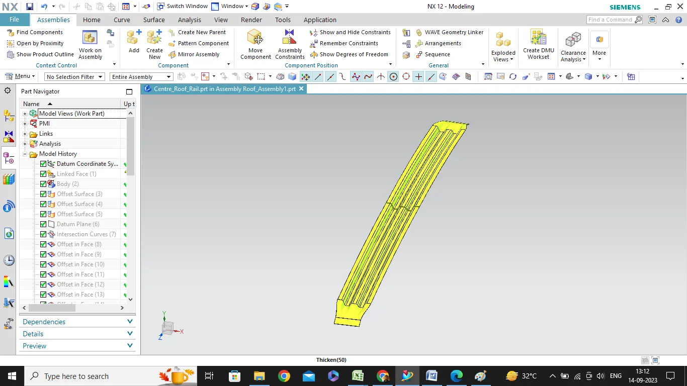 <!--[endif]-->
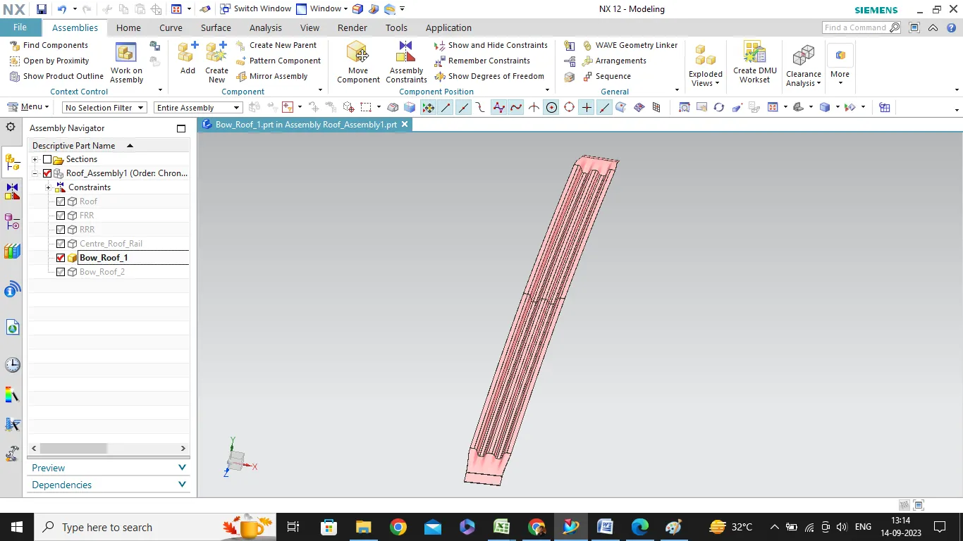
Bow Roof Rail 1: -
Bow Roof Rail 2: -
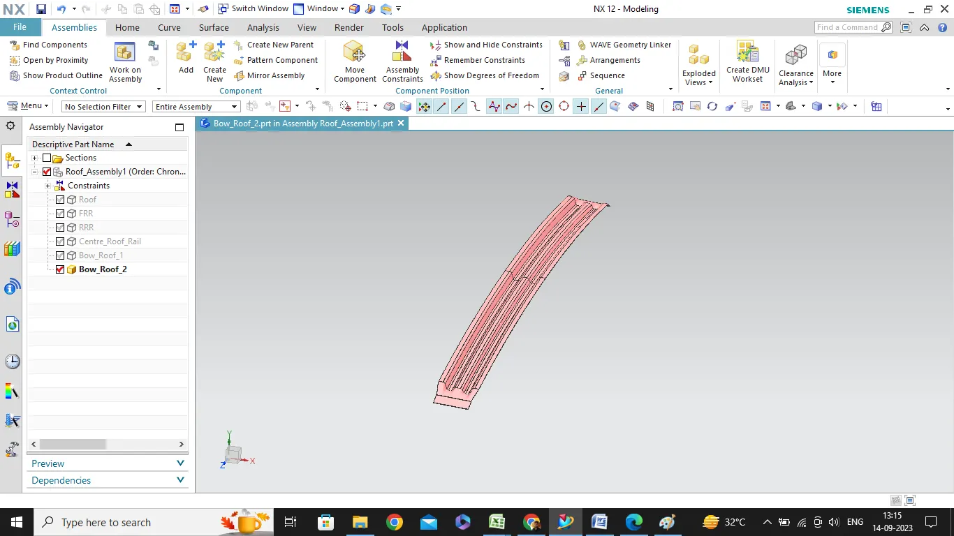
<!-- [if !supportLists]-->· <!--[endif]-->These reinforcement roofs are provided to give additional support to the Roof Panel as per the requirements.
<!-- [if !supportLists]-->· <!--[endif]-->Depth of the middle flange is decided as per the headliner that goes in.
For joining the outer panel with the Reinforcement Roofs, Mastics are used along with Spot Welds at some places to make an entire assembly.
Roof Tests
<!-- [if !supportLists]-->· <!--[endif]-->To test whether the Roof is right or not, the very important test for this is the ROLL-OVER test and thus, in this situation we’re doing a ROOF CRUSH test.
<!-- [if !supportLists]-->· <!--[endif]-->The design of this test is given by the Insurance Institute of Highway Safety (IIHS), and after analyzing many accidents they’ve fixed some regulations and based upon these regulations, they give the rating on: -
How fast the car reforms to the original shape or how deep the protrusion is after the collision.
Objective of Roof Crush Test: -
<!-- [if !supportLists]-->· <!--[endif]-->To check the strength of the Roof, certain tests are being carried out among which the Roll-over test is the most important one.
<!-- [if !supportLists]-->· <!--[endif]-->To check the protrusion on the Roof in case of a Roll-over situation.
Initial condition of the test sample: -
<!-- [if !supportLists]-->· <!--[endif]-->Close and lock all the doors.
<!-- [if !supportLists]-->· <!--[endif]-->Close all the windows.
Fixing the test sample: -
<!-- [if !supportLists]-->· <!--[endif]-->Fix the body sill or chassis frame on a hard, level surface horizontally and only the BiW is used in this test.
Test parameters: -
<!-- [if !supportLists]-->· <!--[endif]-->Crush Speed – 13 mm/s or less
<!-- [if !supportLists]-->· <!--[endif]-->Load and displacement specifications –
The displacement of the load application device is 127 mm or less when a load of 1.5 times the vehicle weight or 22,240 N, whichever is smaller, is applied as shown.
<!-- [if gte vml 1]>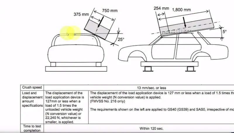 <!--[endif]-->
Conclusion: -
<!-- [if !supportLists]-->· <!--[endif]-->From the above test various graphs are obtained viz. the LOAD-DISPLACEMENT, LOADING-TIME.
<!-- [if !supportLists]-->· <!--[endif]-->If DISPLACEMENT > Requirement, then, following measured can be adopted for the strength improvement:
<!-- [if !supportLists]-->1. <!--[endif]-->Increasing the no. of MASTICS or SPOT WELDS.
<!-- [if !supportLists]-->2. <!--[endif]-->Increasing the BOW ROOF thickness.
Curvature Study or Bow Roof position justification: -
Heat distortion Criteria : -
This theoretical study is done to check the ability of the roof to withstand high temperatures with respect to the positioning of the reinforcements which contribute to increased strength.
Governing Equations:
Heat Distortion or Bow-Roof Prediction Formula:
W = [1.73 * 10^ (-3) * L] + [1.85 * 10 ^ (-8) * (R^2)/t] + [1.1 * 10 ^ (-3) * l] - 2.68
Where,
L = Roof Length along 0-Y direction (in mm)
R = Roof Curvature
R = 2(Rx * Ry) / (Rx+Ry)
Rx – X curvature, Ry – Y Curvature
t – Roof plate thickness (in mm)
l – Bow Roof Span (in mm)
Judgement criteria: -
W< 2>
Calculations: -
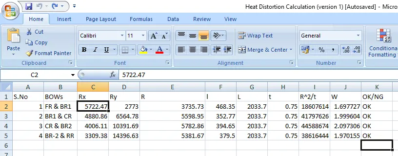
<!-- [if !supportLists]-->· <!--[endif]-->All the four cases pass the heat distortion criteria.
Snow Load Prediction Formula: -
Qr = [ Iy * t^2] / [ α * s * ((Rx+ Ry)/2) ^ 2 * 10 ^ (-8)]
where,
α = My * Lx^2 * 10 ^ (-12), My = y (Ly – y)
t = Roof plate thickness (in mm)
Ly = Distance between the front and rear roof Rails on the Vehicle along with 0Y[mm]
Length of Roof panel with the center point between Roof rail Front /Rear as the front and rear reference point.
Lx = Distance between the Left and Right end of the roof on the Roof BOW [mm]
The width of the roof panel is exposed on the surface.
Y = Distance Front Roof Rail to Roof BOW [mm]
s = Distance for which Roof BOW bears divided load [mm]
s = L1/2 + L2/2
Iy = Geometrical moment of inertia of Roof BOW (Y cross-section) (mm4)
Rx = Lateral direction curvature radius of roof panel Y cross-section on Roof BOW [mm]
Roof panel curvature Radius of the Length Lx in Front view
Ry = Longitudinal Direction curvature radius of the Roof panel X cross-section on Roof BOW [mm]
Judgment condition
Qr ≥ 3.1
Calculation: -
<!-- [if gte vml 1]>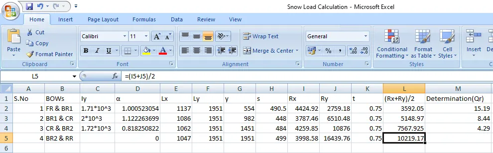 <!--[endif]-->
<!-- [if !supportLists]-->· <!--[endif]-->In this situation, except Case 4, rest other cases, passes the fitness criteria.
If the Snow Load Criteria didn’t get satisfied/ NG :-
<!-- [if !supportLists]-->· <!--[endif]-->In that case we need to modify the localized radius of curvature, R, i.e., Rx & Ry for unsatisfied cases using Trial and Error to get the desired results during the time we get the Styling / Class A itself.
<!-- [if !supportLists]-->· <!--[endif]-->The radius of curvature of the entire roof is gradually increased, in order to modify the localized Rx & Ry values, so that we get atleast the required value at the needed location.
<!-- [if !supportLists]-->· <!--[endif]-->Sometimes, even the Stylist won’t accept the NG value, i.e., not allowing the modifications on Rx & Ry values. In that case, we need to provide local embosses over the roof to get the OK condition, while providing the strength improvement also.
Conclusion for Bow Roof Positioning: -
<!-- [if !supportLists]-->· <!--[endif]-->First, we need to check the centre between the two roof rails, if its flat we’ll position the BOW roof there, and, if it's not we’ll look out for other areas near the centre position for the flatter surfaces and then position the bow roof tentatively over there.
<!-- [if !supportLists]-->· <!--[endif]-->Then, the feedback is given to styling colleague to modify the respective Rx & Ry values, because after we position the BOW roof, we’ll come to know about their mastic influence, so we have to position our bow so that it doesn’t interferes with the mastics. Our intention is to reduce the non-mastic influence area, so that I get better roof strength.
<!-- [if !supportLists]-->· <!--[endif]-->In case the designer isn’t accepting modifications of localized Rx & Ry, in that case we’ll provide embosses. Numerous types of embosses can be given for this.
Physical Snow Load Test: -
<!-- [if !supportLists]-->· <!--[endif]-->Apart from the theoretical heat distortion test and the snow load test, a physical snow load test is done on the roof to check the snow load bearing capacity of the roof in case of heavy snowfall situations and rate at which the roof reforms to its original shape.
<!-- [if !supportLists]-->· <!--[endif]-->Dead weights on the inside of the roof is used to create a similar situation. The requirement here is that when the dead weights are removed, roof should should come back to its original state.
Draft Analysis: -
Roof Back Side: -
<!-- [if gte vml 1]>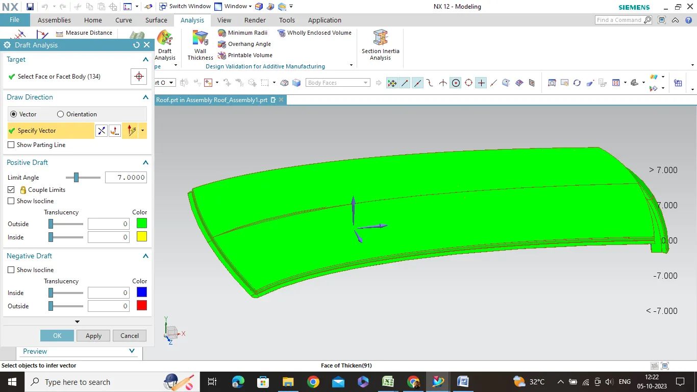 <!--[endif]-->
<!-- [if gte vml 1]>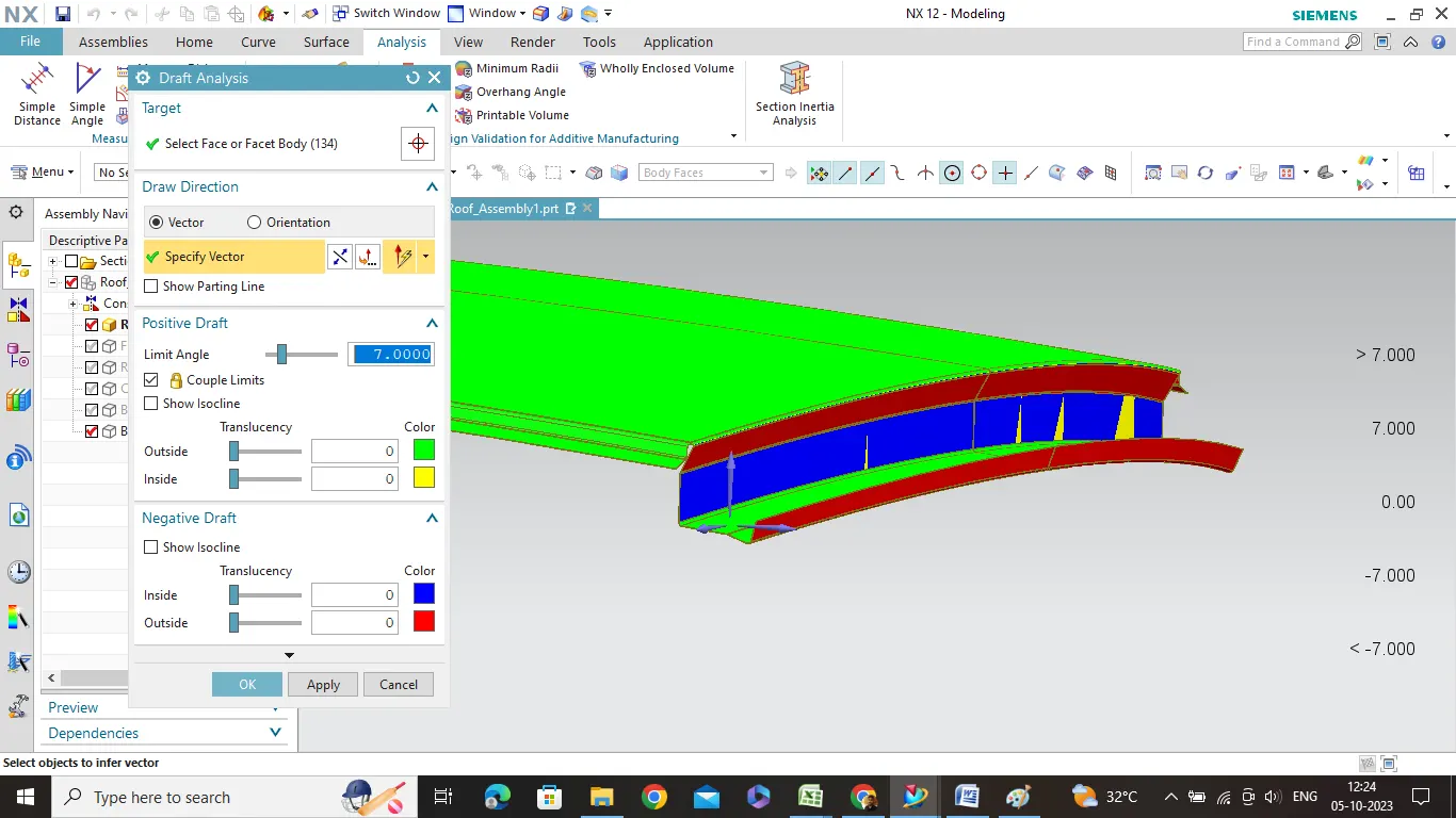 <!--[endif]-->
<!-- [if !supportLists]-->· <!--[endif]-->The backside of the roof didn’t seem to be passing the minimum draft requirements and for manufacturing that we’ll be using Offset Bending Operation.
Bow Roof 1: -
<!-- [if gte vml 1]>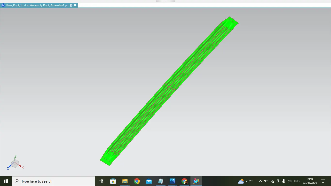 <!--[endif]-->
Bow Roof 2: -
<!-- [if gte vml 1]>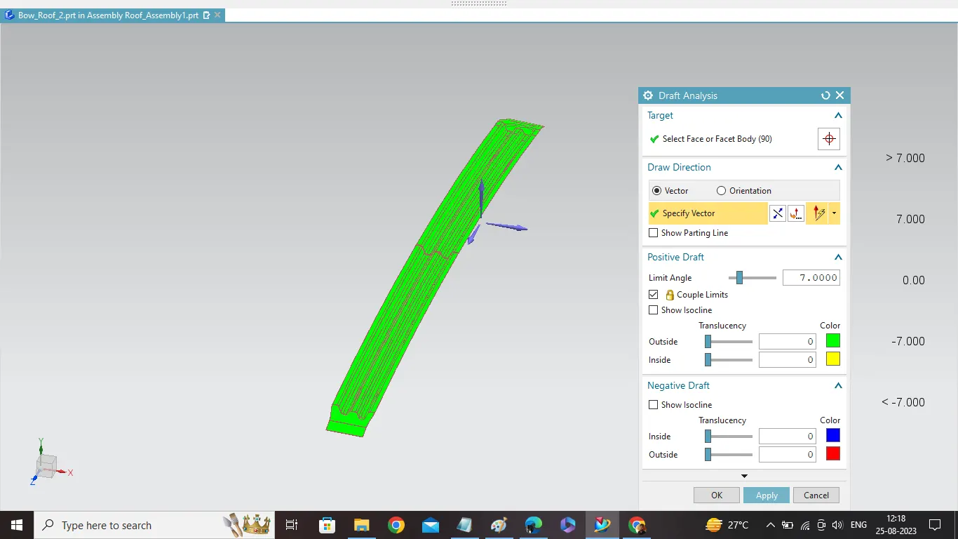 <!--[endif]-->
Front Roof Rail: -
<!-- [if gte vml 1]>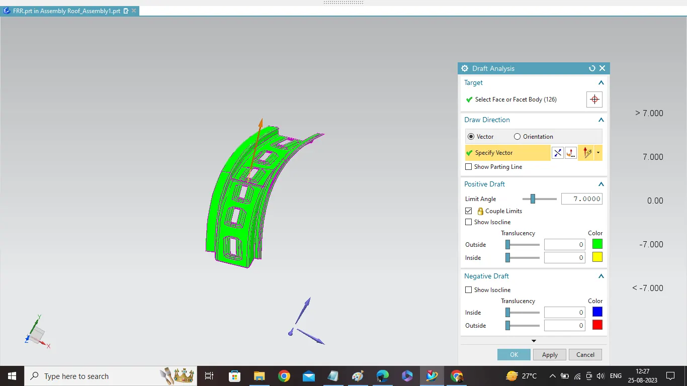
<!--[endif]-->Centre Roof Rail: -
<!-- [if gte vml 1]>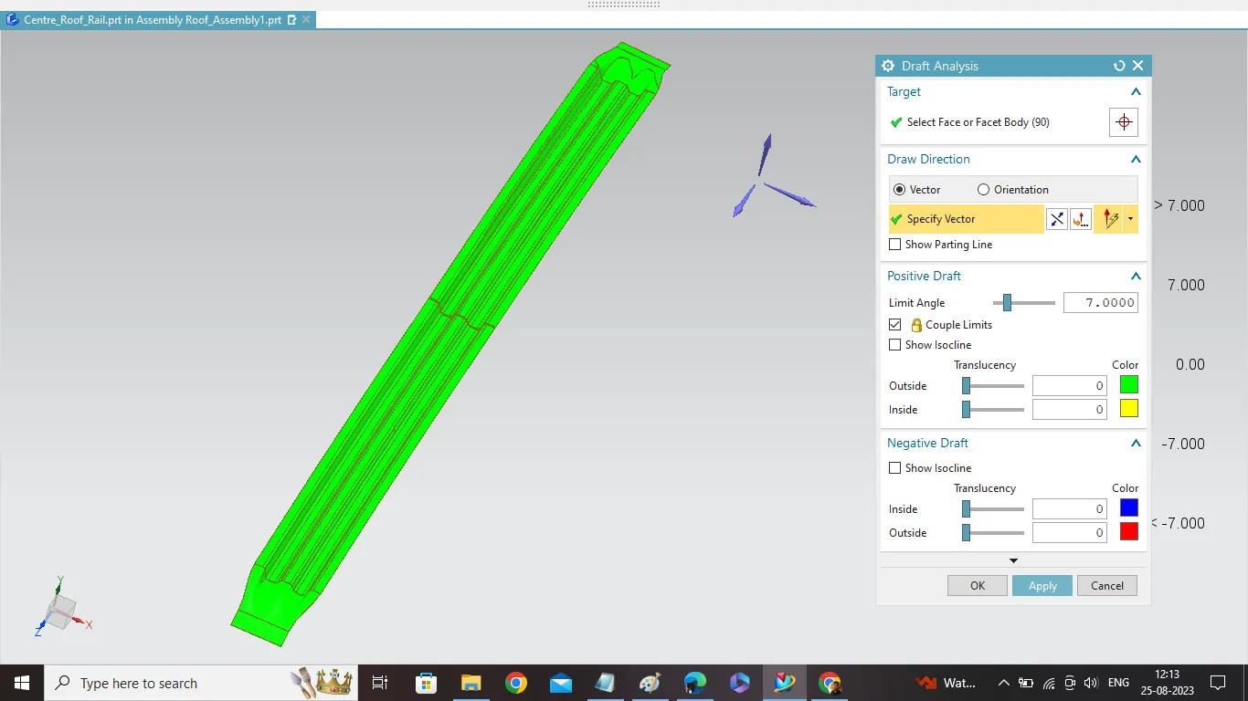 <!--[endif]-->
Rear Roof Rail: -
<!-- [if gte vml 1]>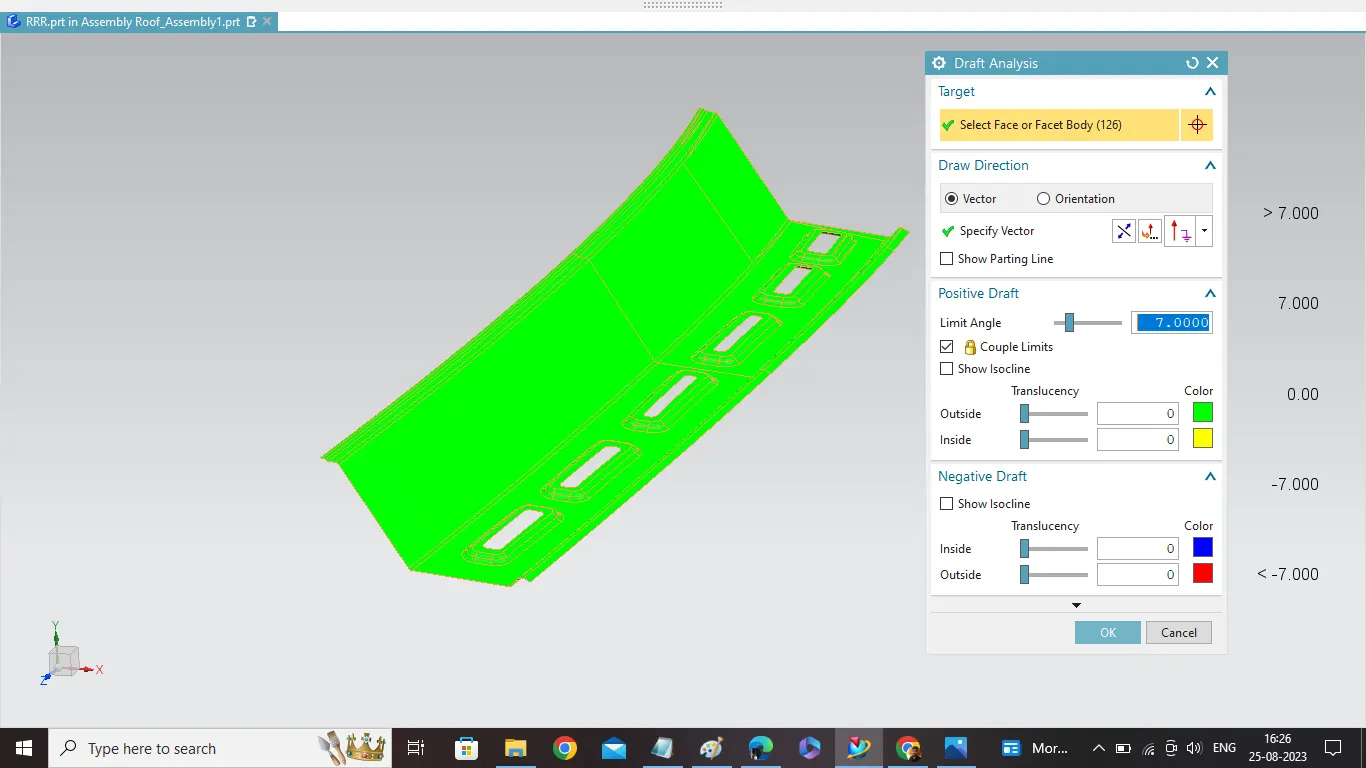 <!--[endif]-->
Conclusion: -
<!-- [if !supportLists]-->· <!--[endif]-->Top-Down approach is followed while designing the Roof Assembly.
<!-- [if !supportLists]-->· <!--[endif]-->Roof designing consists of designing its individual components to get the entire Roof assembly as per Master Sections and the laid down standards
<!-- [if !supportLists]-->· <!--[endif]-->Embosses can be provided whenever needed for remarkable strength improvements.
<!-- [if !supportLists]-->· <!--[endif]-->Bow Roof positioning is done as per the Heat Distortion and the Snow Load Criteria.
<!-- [if !supportLists]-->· <!--[endif]-->Whenever there’s a joinery, spot welds are done between them for which the common land area of 15 mm is given and the pitch between two spot welds is 20-25 mm for proper joining.
<!-- [if !supportLists]-->· <!--[endif]-->Laser brazing is an expensive operation, so we usually do spot welds.
<!-- [if !supportLists]-->· <!--[endif]-->Joining of the bow roofs rails with the outer roof panel is done using mastics so that no compromises is being made on aesthetics part while provide great strength to the roof assembly.
References: -
<!-- [if !supportLists]-->· https://www.iihs.org/media/46940e89-46cb-4e6e-81ee-8230bb3b5dd9/0dx8eA/Ratings/Protocols/current/test_protocol_roof.pdf.
Note: -
<!-- [if !supportLists]-->· <!--[endif]-->Provisions for mastic positioning on the Bow Roof should’ve been given but was realized at a later stage. So, cut-out for mastics is being ignored.