Roof Crush - BIW
AIM :-
To conduct roof crush analysis of BIW with FMVSS
OBJECTIVE:-
- Run the model.
- Plot force vs. displacement. Check that the FMVSS 216 target load of 47,000 N (= 3 * GVW) has been met.
- Plot the energy vs. time curve.
THEORY:-
what is crash test ?
A crash test is a form of destructive testing usually performed in order to ensure safe design standards in crashworthiness and crashcompatability for various modes of transportation (see automobile safety) or related systems and components.
Crash is the explicit analysis. Explicit dynamics analysis is used to determine the dynamic response of a structure due to stress wave propagation, impact or rapidly changing time- dependent loads. Momentum exchange between moving bodies and inertial effects are usually important aspects of the type of analysis being conducted. This type of analysis can also be used to model mechanical phenomena that are highly nonlinear. Nonlinearities may stem from the materials, (hyperelasticity, plastic flows, failure), from contact (high speed collisions and impact) and from the geometric deformation (buckling and collapse). Events with time scales of less than 1 second (usually of order milliseconds) are efficiently simulated with this type of analysis. Based on all these conditions the user will select an explicit solver to solve the analysis. Typical examples of explicit analysis are crash analysis, drop test, bird strike, fan blade out…etc. Obtaining an answer from an explicit simulation can be simple — it can be more challenging to get the correct answer. The predictions of a simulation are usually very difficult to confirm using traditional techniques, making it crucial that the analysis is carried out carefully and thoroughly. Nonlinear analysis requires a lot of experience and a careful understanding of what you want to achieve, as well as a careful understanding of the software's analytical capabilities. When choosing a method for a dynamic problem, considerations must be made regarding the length of time the response can take place compared to the explicit method's stability limit.
Types of crashes tested
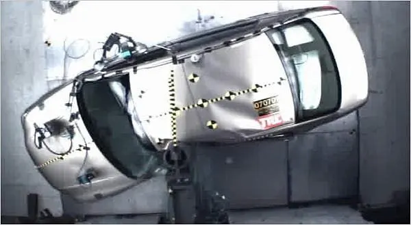
There are three types of crash frontal , side , and roof crash

FRONTAL CRASH
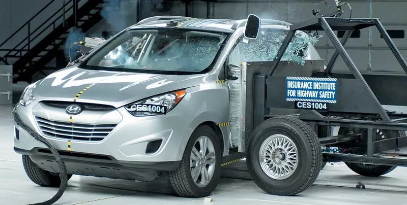
SIDE POLE CRASH SIDE CRASH
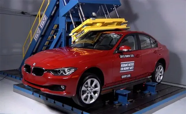
ROOF CRASH
ROOF CRASH
It is an quasi static analyisis
Rollover accidents of a car are the most occurring accidents that we see in our daily lives. The passengers experience major injuries like neck, head and spine injuries. So, to reduce the injuries of a passenger from major fatalities it is important to provide safety in the car. Though safety is provided by seat belts and airbags during accidents, the passenger must have sufficient space for survival in the car during accidents. The roof of the car must have high strength to resist the crush force to avail the passenger some space for survival. Therefore, in this project, we have carried out roof crush test using Federal Motor Vehicle Safety Standards.
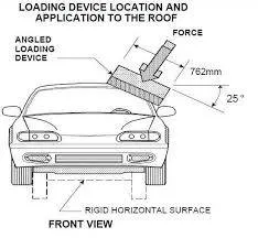
In the test, the strength of the roof is determined by pushing an angled metal plate down on one side of the roof at a slow but constant speed and measuring the force required to crush the roof. The force applied relative to the vehicle's weight is known as the strength-to-weight ratio. The peak strength-to-weight ratio recorded at any time before the roof is crushed 5 inches is the key measurement of roof strength.
A good rating requires a strength-to-weight ratio of at least 4. In other words, the roof must withstand a force of at least 4 times the vehicle's weight before the plate crushes the roof by 5 inches. For an acceptable rating, the minimum required strength-to-weight ratio is 3.25. For a marginal rating, it is 2.5. Anything lower than that is poor.
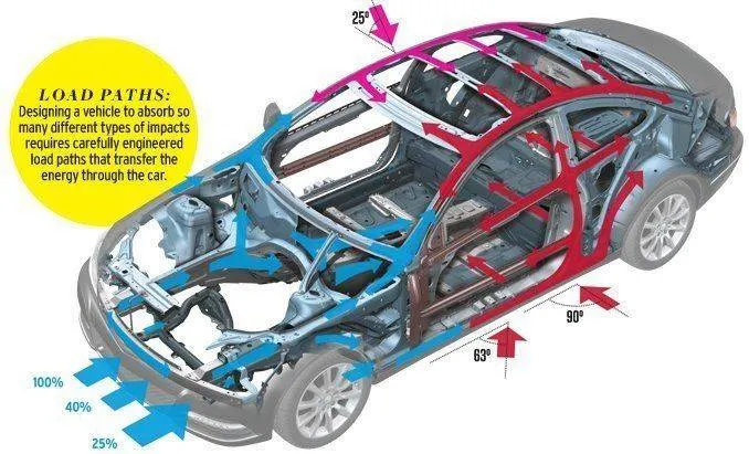
Below image shows the direction of forces acting
METHODOLOGY :-
- Import model & Impactor
- Remove unnecessaty control cards,Unnecessary Interface
- Set Impactor according to condition
- Create Interface & Check for penetrations
- Apply kinematic condition
- create Mandatory conrol cards
PROCEDURE:-
1:-IMPORT THE FILE
- Open the hyper mesh software and select the profile as radioss
- Go to file and click on the import and select the import solver deck
- click on the file option and select the file _0000.rad
and click on the import as shown in fig 1.1
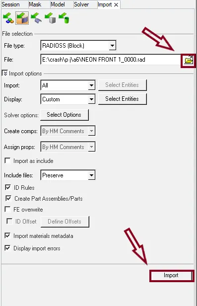
Fig 1.1
- After importing the model the model is as shown fig 1.2
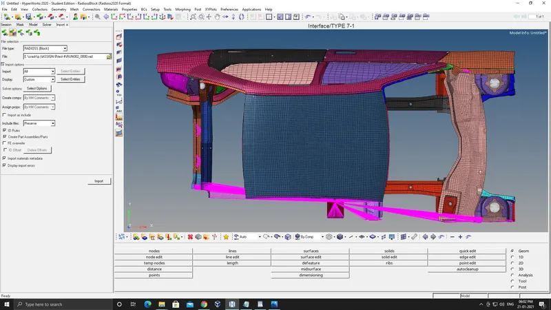
Fig 1.2
- And then we have to import the impactor to this model and set the impactor to the position as following
- A 180° rotation about the global z-axis with the point opposite to C as base point
- A 5° rotation about the axis through axis AB
- A 25° rotation about the axis through axis AC
- A translation to put point A at global ( -3500.00, 584.822, 1343.06)
- Impactor should be as shown in the fig 1.3
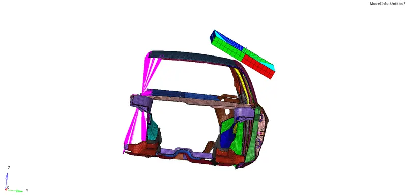
Fig 1.3
2:-SET UP FOR THE FRONTAL CRASH OF NEON FRONT
1 :- Check unit system and either follow[Mg mm s] or [Kg mm ms].
- In engine cards we can see the BEGINE_CARD there we can check the units followed in the model as shown in fig 2.1
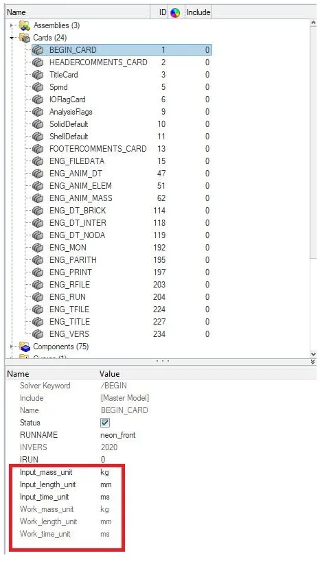
Fig 2.1
- Units used in the model is [Kg mm ms]
2 :- Create appropriate interface ,friction 0.2 and recommended parameters.
- Here we have to create 2 contact interfaces one is for self interface and other one is to get forces near bumper area . Both interfaces are having Recommendations interfaces with gap mim 0.5 and friction 0.2
- And the recommended parameters are shown in the below fig 2.2
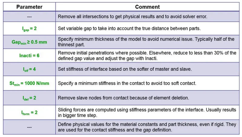
Fig 2.2
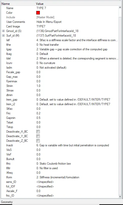
- Here we are using only TYPE 7 interface for the type 7 interface these are parameters used
- To create the type 7 interface we can use hypermesh or hypercrash in hypermesh as shown in fig 2.3
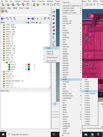
Fig 2.3
- Parameters are set as recommonded shown in fig 2.4
- For the self contact interface we have to give master and slave as car components as shown in the fig 2.5
- Where the Blue colour is the master and red colour is the slave
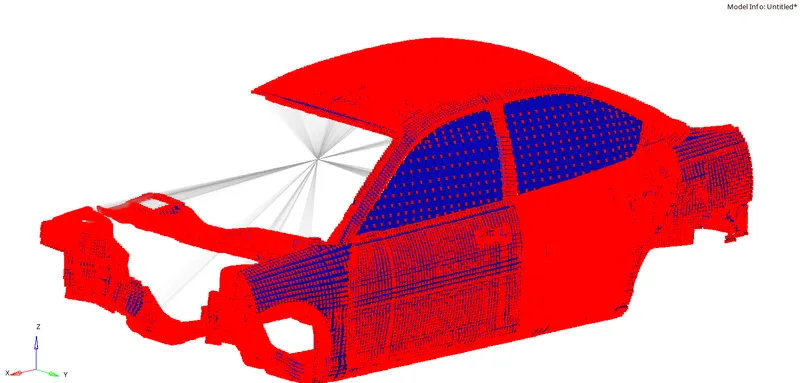
Fig 2.5
- And then we have to create the type 7 interface to the car and the impactor where the car is the slave and impactor is the master as shown in the fig 2.6
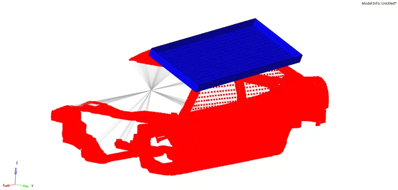
Fig 2.6
3 :- Make sure of no penetrations and intersection.
- To check the penetrations and intersection we have to open the hypercrash
- To open the hypercrash click on the applications and select the hypercrash and set the units to [Kg mm ms] an run
- And import the model by dragging the file into the hypercrash
- Cllick on the quality and select the check all intersections the window shows as below fig 2.7
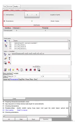
Fig 2.7
- There are no penetrations and intersection in the model
4 :- keep the suspension shock tower nodes locked in Z.
- We have to create the rigids on the suspention and the Z should be locked as shown in the fig 2.8
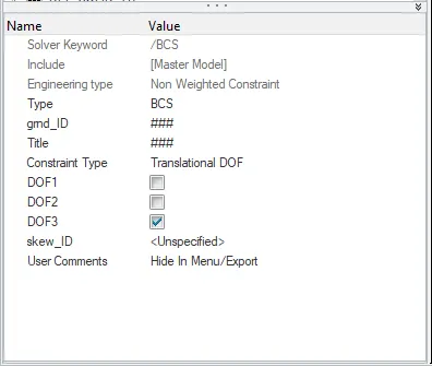
Fig 2.8
- The rigid bodies are created as shown in the fig 2.9
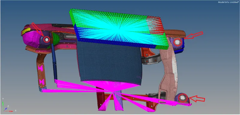
Fig 2.9
5 :- Impactor Boundary Conditions
- Impactor have a spring one end is connected to the rigid and another is free end at the free end we have to lock the all directions as shown in fig 2.10
- To create BCS Solver>create>boundary conditions>BCS
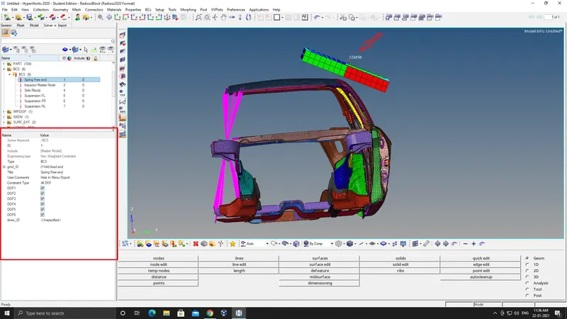
Fig 2.10
- By creating the BCS at the free end of the spring by locking all directions the impactor can move only in one direction the direction which the another end moves
- Then we have to create a moving skew for the impactor
MOVING SKEW :- Skew is one type of reference coordinate system which helps in defining local quantities with respect to the global coordinate system.Here the origin of the skew remains in a fixed position even if it is a fixed skew or moving skew.In a moving skew, the orientation of the node of interest is recomputed everytime, with that of the origin coordinates of the skew. Skew is most widely used in most of the RADIOSS inputs.
- To create mov skew Solver>create>skew>mov and the we have to give the nodes which the direction Z should be towards the car as shown in the fig 2.11
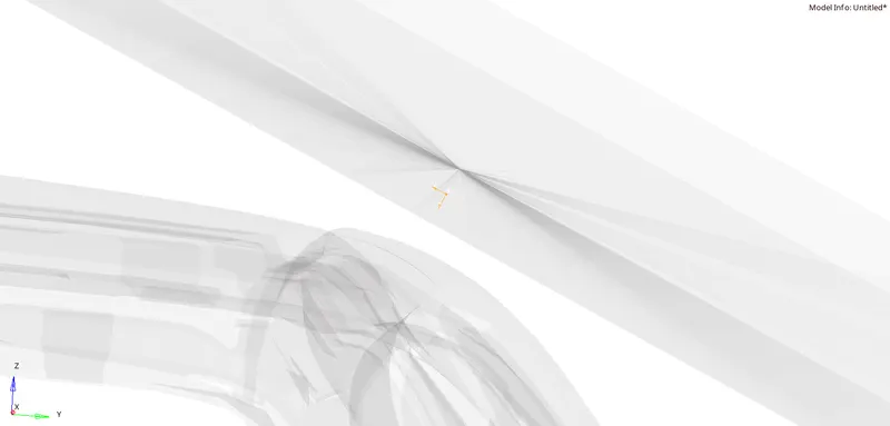
Fig 2.11
- As we created the skew and the Z is the direction towards the car so then we have to create BCS of the master node of the impactor rigid body where only Z transulation is uncheck as shown in the fig 2.12
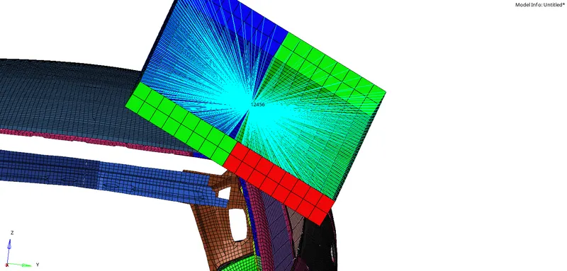
Fig 2.12
- So we can move the impactor only in Z transulation with respect to the skew towards the direction of the car
-
lly as suspection system is removed in default model we have to create rigid connection on shock towers and have to contrain its motion in atleast in z direction as suspensions translate in z direction.
6 :- Imposed Displacement
- Impose the velocity of the impactor starting from 0 mm/s at t = 0.The displacement of the impactor should be 200 mm @ 200 ms.
- To create the imposed velocity for an impactor First we have to create a curve MOdel>create>curve there we have to give the values as shown in the fig 2.13
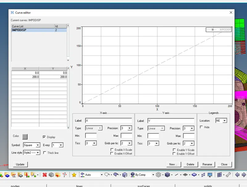
Fig 2.13
- Click on update and close and then create IMPODISP
- To create IMPODISP Solver>create>Boundary conditions>IMPODISP
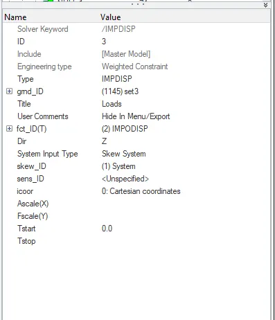
Fig 2.14
- There in gmd_ID we have to give the master node of the rigid of the impactor in fct_ID we have to give the curve we created and in skew id we have to give the skew we created
- So we are giving the impactor IMPOSED DISPLACEMENT 200mm towards the car
7 :- create Mandatory conrol cards
- We have to create cards which are mandatory to run the simulation below fig 2.15 shows the cards
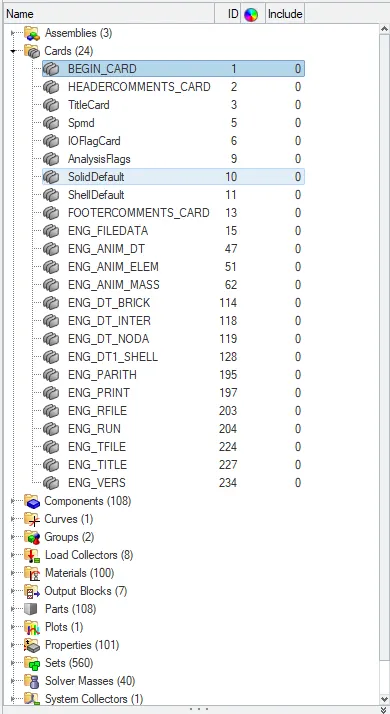
Fig 2.15
- Print time history every 0.0001 seconds
- Solve for 200 ms in ENG_RUN
- Create an animation file every 0.005 seconds in engine_anime_DT
8 :- Set up model checker
- Before creating animation it is always best practice to eliminate error to get accurate results or some times due to these errors animation files dosen't gets created.(Hypercrach>>Quality>>Model check>>Run) As we see in fig 2.16 there were o errrors & some warning found while on running model checker. all warnings are not harmful but errors must be eleminated before running simulation.
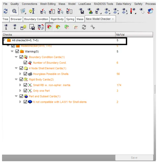
Fig 2.16
3 :- Results and simulation
- Before running the simulation make sure to delete the unused and run the model checker TOOLS>MODEL CHECKER>RADIOSS BLOCK
- If there is any errors or incompatable kinamatic contitions fix the error and run the simulation ANALYSIS>RADIOSS>RADIOSS simulation shown in GIF 3.1
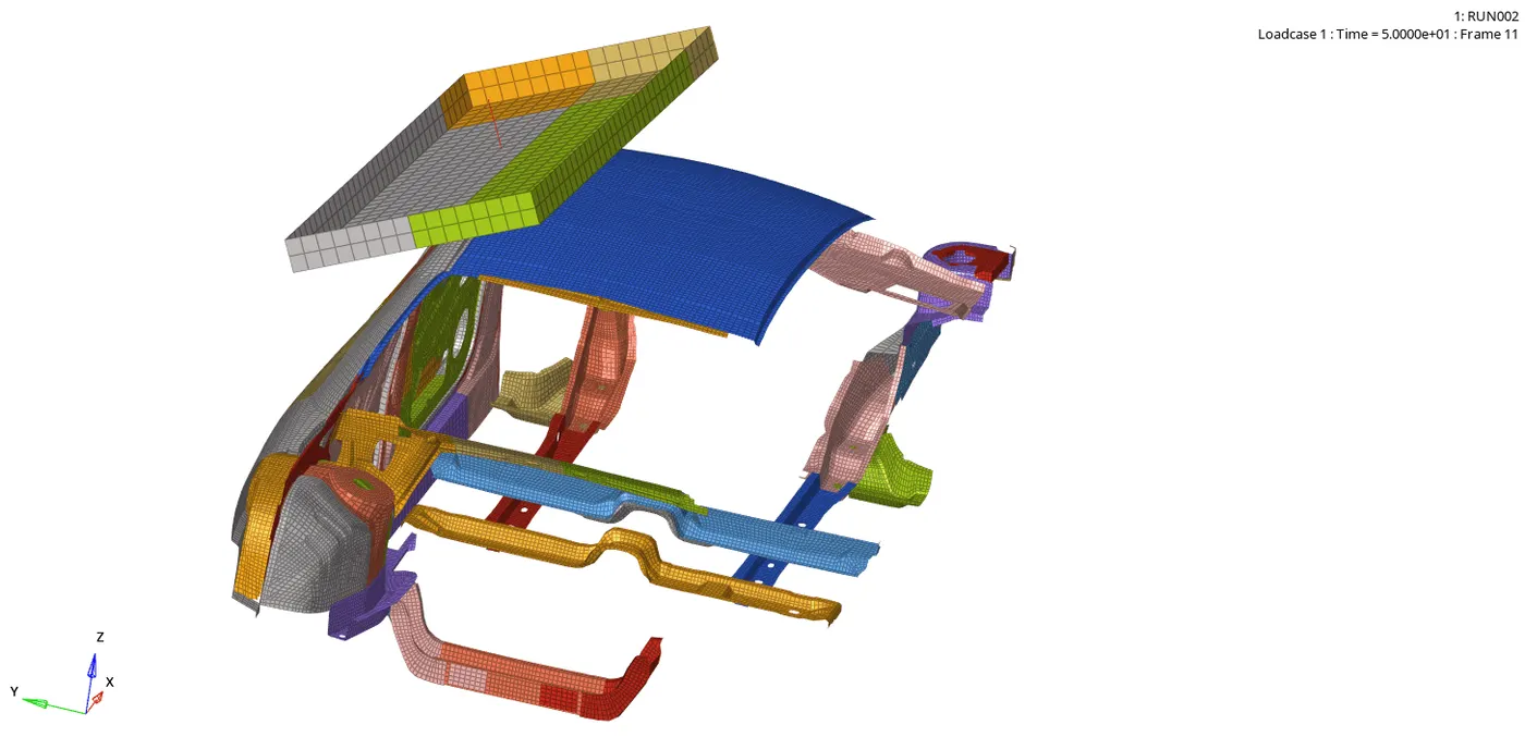
GIF 3.1
- After running the simulation check for the energy error and mass error as shown in fig 3.1
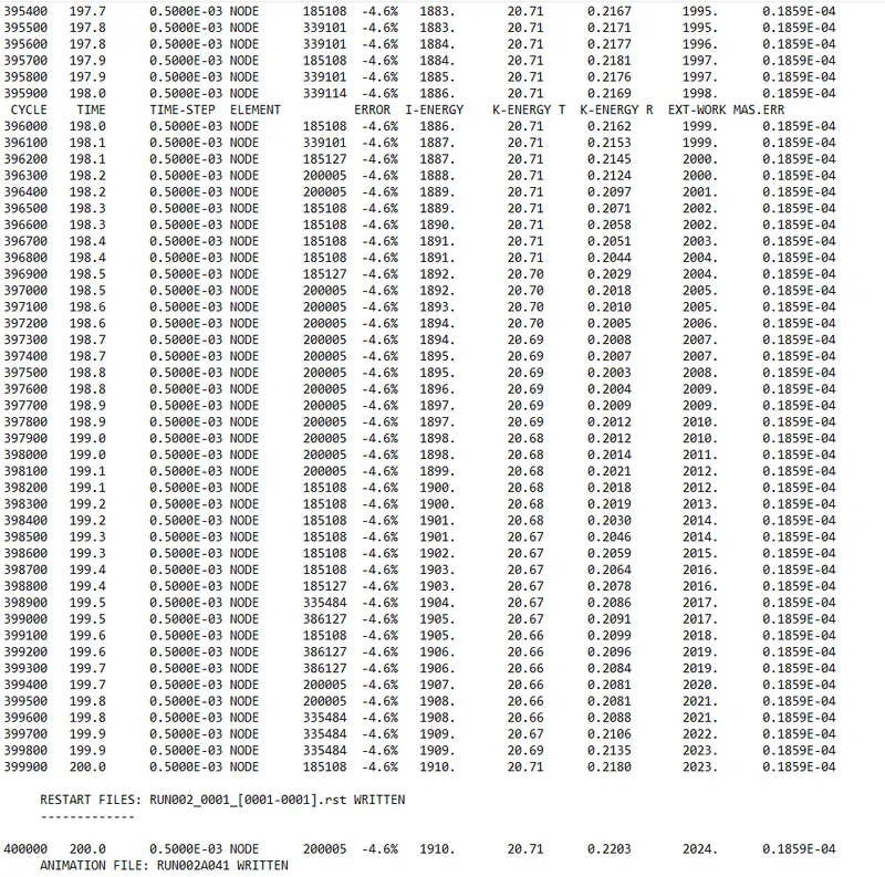
Fig 3.1
- energy error is -4.6% and mass error is 0.1859E-04 the model is good
- And the time taken for the simulation is 3778.97 s and number of cycles is 400001
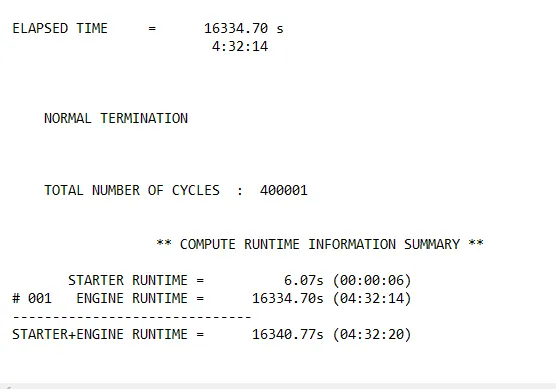
- We can see these results in the 0001.out file
- vonmisses in GIF 3.3 of the model
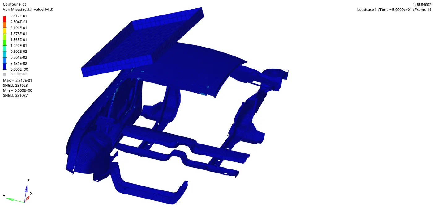
GIF 3.3
- Maximum Von mess stress occure is 2.85 Mpa
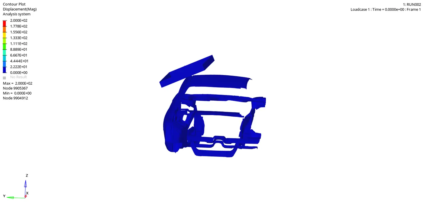
GIF 3.4
- Maximum displacement is 2.00E+02 mm
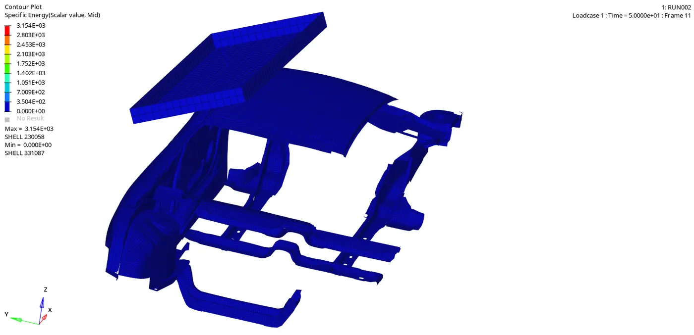
Elemental energy GIF 3.5
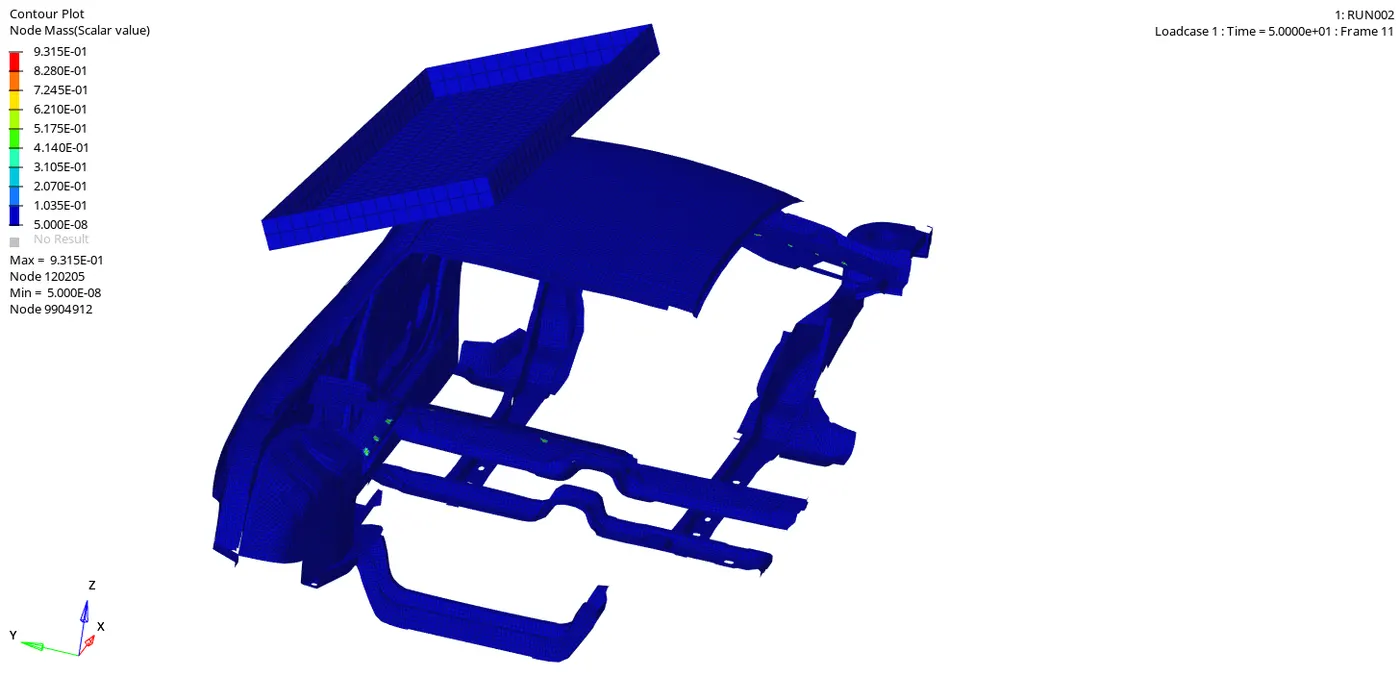
Nodal masses GIF 3.6
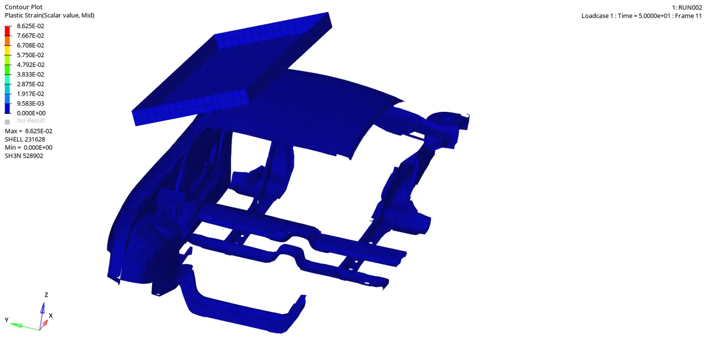
Plastic strain GIF 3.7
4:-plotting graphs
- To plot graph change it to the HYPER GRAPH 2D and select the T01 file
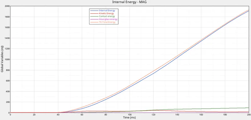
4.1 :- Graph 4.1 shows the IE ,KE ,CE ,HE ,TE to time
Graph 4.1
- we have Total Energy = Internal Energy + Kinetic energy + External Work, here we dont have KE the external work is acting by the impactor so the IE and TE are keep increasing and there is light deviation in the KE and HG some components are moved and the energy lose is happend in the model
- Hourglass energy is almost constant because both are controlled by elements formulation. here hourglass is controlledby Physical stabilization i.e changing material level in ISHELL is 24 QEPH Shell formulation.
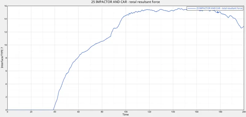
4.2 :- Graph 4.2 shows the force absorbed by the car from the impactor in time
Graph 4.2
- Max force is 15.6215 KN @145ms
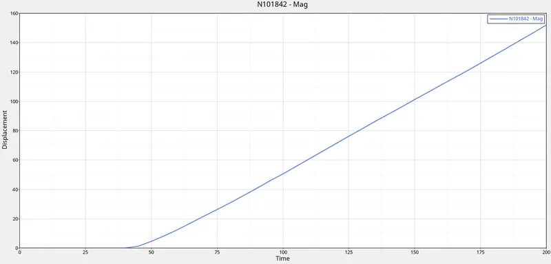
4.3 :- Graph 4.3 shows displacement of node on car is 200mm
Graph 4.3
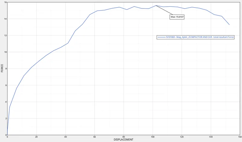
4.4 :- Graph 4.4 shows the cross plot of Plot force vs. displacement
Graph 4.4
- Max force is 15.6107 KN at 105 mm displacement
-
Strength to weight ratio=Resistive Force/Gross weight of the Vehicle
47,000 N (= 3 * GVW) has been met.
Resistive Force = Strength to weight ratio*Gross weight of the Vehicle
Resistive Force = 3*9.81*174.05 = 5122.29N , this is the theoretical value.
Resistive force is Not exceed the 47000N, the Car is safe
-
From the graph
we have Resistive Force is 17.43KN = 17430 N
Gross weight of the Vehicle is 174.05*9.81 = 1,707.43 N
Strength to weight ratio=Resistive Force/Gross weight of the Vehicle
Strength to weight ratio = 17430/1,707.43 = 10.2
Strength to weight ratio 10.2 because we taken only BIW Gross weight of car ,
suppose consider the total car weight 700 Kg
Strength to weight ratio = 17430/700*9.81 = 2.5 so it is Marginal
CONCLUSION-
- COG and mass distribution plays vital role in analysis
- Make sure the all parts are connected accordingly to manage energy error
- Rigid bodies must be created over removed parts & degree of freedom must be arrested according to motion
- As maximum force developed is way less than target load I can conclude that Roof crash test was successful.