ROOF CRASH ANALYSIS OF A PASSENGER CAR BIW FOR VEHICLE SAFETY AS PER FMVSS 216 STANDARD
ROOF CRASH ANALYSIS OF A PASSENGER CAR BIW FOR VEHICLE SAFETY AS PER FMVSS 216 STANDARD
AIM:
To study and validate the structural integrity and safety level of the BIW assembly under the roof crash scenario in accordance with the FMVSS 216 standard.
INTRODUCTION:
Roof crush is the failure and displacement of an automobile roof into the passenger compartment during a rollover accident. Roof crush has also been identified as a cause of both full and partial ejection in rollover accidents because of ejection portals created by the collapsing roof structure. These chiefly involve broken windows but occasionally also involve the body structure. Two of the principal causes of injury during rollovers are occupant ejection and roof crush. Occupant ejection in rollover crashes would be prevented by seat belt use and other ejection mitigation features such as improved side curtain air bags and advanced window glazing. Crushing of a vehicle roof into an occupant compartment during a rollover could be mitigated by a stronger roof structure. The need for stronger vehicle roof structure led to creation of the vehicle safety standard for roof crush resistance.
FMVSS No. 216a. One of the important requirements specified in the standard involves roof strength measured in the strength-to-weight ratio (SWR). The SWR is a unit less metric measuring a vehicle’s roof strength by its own weight. An SWR value is calculated by dividing an applied force by an unloaded vehicle weight as follows,
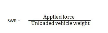
Where applied force and unloaded vehicle weight are measured in the same unit such as Newton (N), thus a calculated SWR is unit less.
The SWR is devised to represent how much a vehicle’s roof structure could withstand its own weight reflecting a rollover event in a crash. A larger SWR value indicates a stronger roof and less occupant compartment intrusion. A vehicle with a larger SWR is more likely to maintain an occupant’s survival space when a vehicle rolls, resulting in a higher survivability and occupant injuries that are less serious.
FMVSS 216 standard criteria:
For the vehicles currently subject to the standard, passenger cars and multipurpose passenger vehicles, trucks and buses with a GVWR (Gross Vehicle Weight rating) of 2,722 kilograms or less, the rule doubles the amount of force the vehicle’s roof structure must withstand in the specified test, from 1.5 times the vehicle’s unloaded weight to 3.0 times the vehicle’s unloaded weight. The rule also extends the applicability of the standard so that it will also apply to vehicles with a GVWR greater than 2,722 kilograms, but not greater than 4,536 kilograms establishing a force requirement of 1.5 times the vehicle’s unloaded weight for these heavier vehicles.
PROCEDURE:
1. Import the given reduced neon model and FMVSS 216 standard impactor to the Hypermesh.
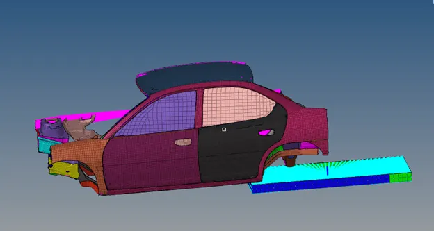
Fig: Imported model and Impactor.
2. The impactor need to be positioned with the car model according to the FMVSS 216 standard, so using transformation tools position the impactor according to the standard as shown in figure. The gap between the car and impactor must be maintained below 10mm.
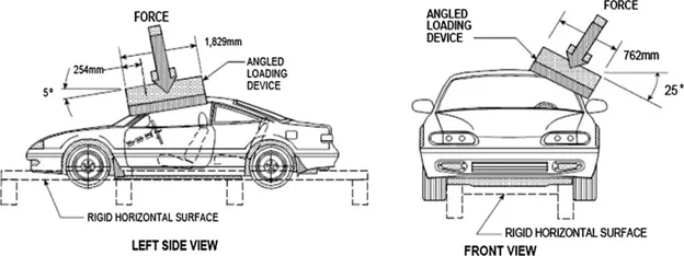
Fig: FMVSS 216 Impactor standard position.
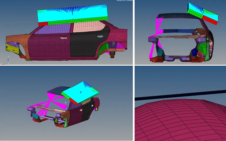
Fig: Impactor positioning.
3. Create 2 contact interfaces of Type 7 in which one interface of self-contact of car and another contact between the car and the Impactor, where the impactor is selected ad master. The contact must be defined with the recommended Type 7 properties as shown.
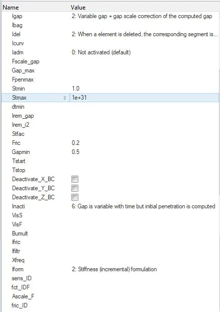
Fig: Type-7 Contact Interface.
4. Check for intersections and penetration using Tools – Penetration check and check for free parts using Tools – Find connectivity. The model had some free parts that can be ignored.
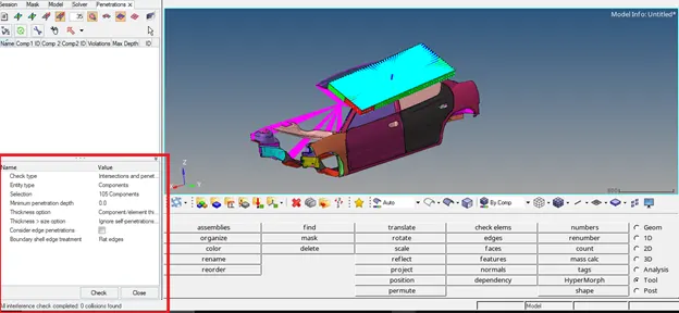
Fig: Penetration Check.
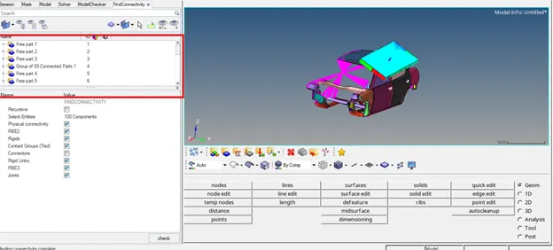
Fig: Connectivity check.
5. Create 1D Rigid elements in the all the 3 locations of the suspension shock tower and lock their DOF in Z direction (DOF 3,6) by unchecking DOF 1,2,4,5 as shown.
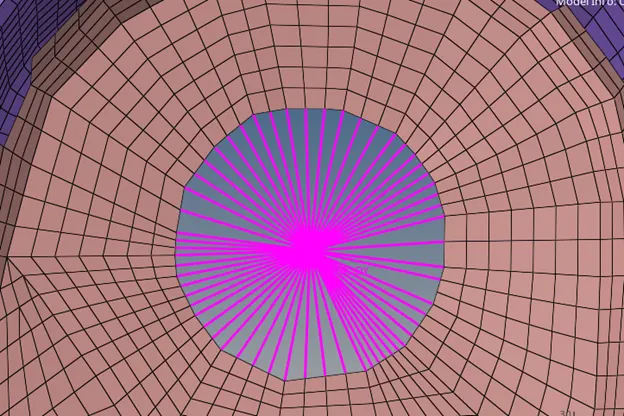
Fig: 1D Rigid element creation.
Boundary conditions:
6. Create a Boundary condition card and select the master nodes of the above created suspension rigid elements, since the DOF in Z has to be restricted so check only DOF3 and DOF6 so that it will be locked in the Z axis.
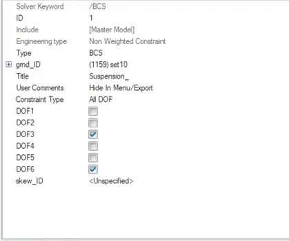
Fig: Suspension Tower Boundary condition.
7. Create a boundary condition to fix the free end of the Impactor spring. The spring end has to be fix and should have any motion so all the DOFs of end node must be restricted. Check all the DOF in the BC card as shown.
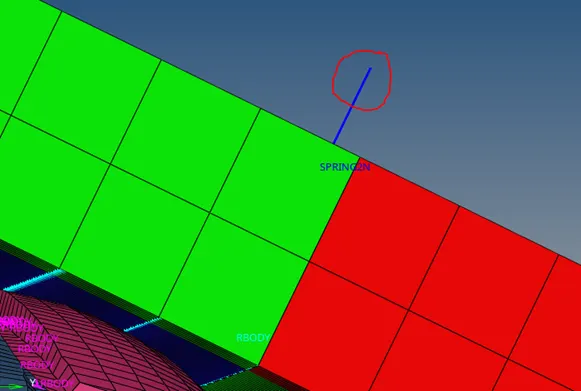
Fig: Free end of the impactor spring.
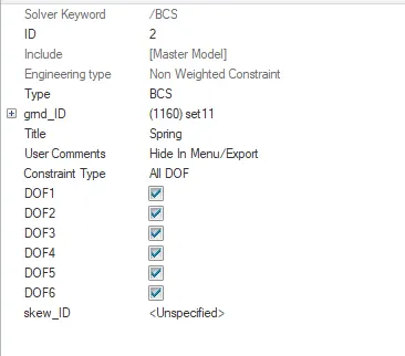
Fig: Impactor spring Boundary condition.
8. Create a moving frame in the Impactor such that the Z axis of the frame must point towards the car as shown in figure. Create a BC card and select the master node of the Impactor 1D rigid elements. Uncheck the Translation motion in Z direction (DOF3) so that it’s free to move in Z and select the frame as the created frame.
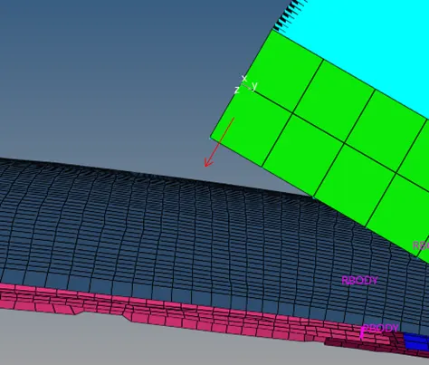
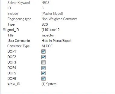
Fig: Created Frame and Boundary condition.
9. Create a Boundary condition to restrict the motion of the car. Select the master nodes of the rigid elements of the car as shown and isolate the motion of the nodes by checking all the DOF.
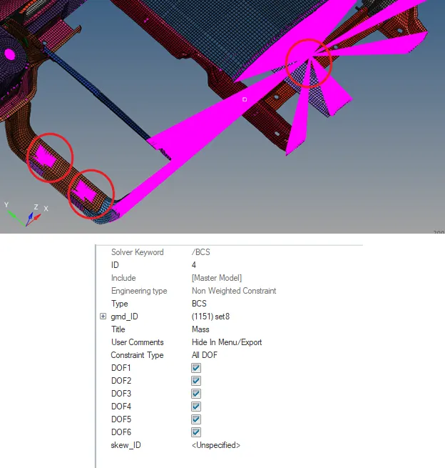
Fig: Location of the master node of Rigid elements and BC.
10. Create Imposed displacement card as shown. Select the master node of the Impactor rigid elements, Create a function curve when 0mm/s at t = 0, 200mm/ms @ t = 200 ms. Select the skew as created frame.
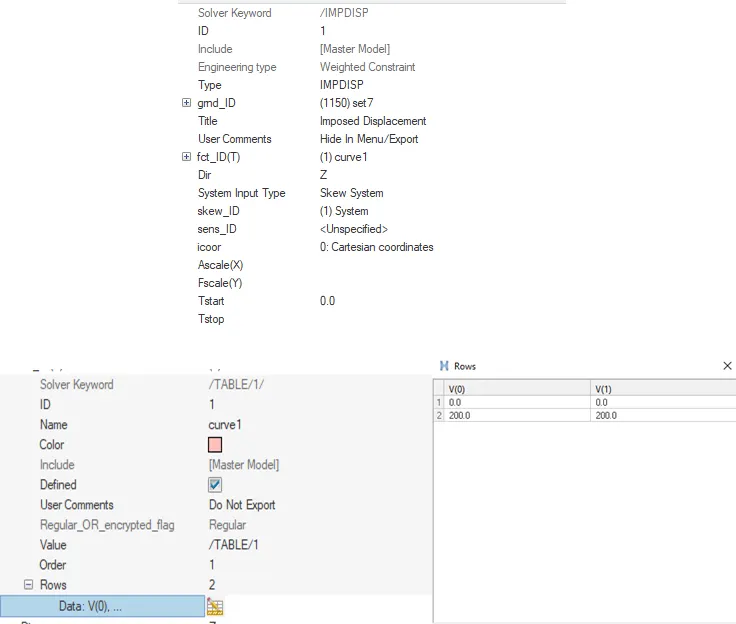
Fig: Imposed Displacement.
11. Crate animation cards like ANIM/MASS, ANIM/VECT, ANIM/ELEM, ANIM/NODA, set ANIM/DT Tfreq to 5 (40 frames).
12. Set the time step of 0.0005ms (0.5microsec) in the DT card and set all DT/SHELL, DT/BRICK, DT/INTER, DT/NODA with constant time step (CST). For Brick and Shell set Tscale value to 0.9 and for rest of the cards set to 0.67. Select the required parameters from the card.
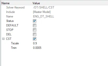
Fig: Time step.
13. The output requests will be created using TH card, create a TH card for the Interface between the Impactor and card and set the variables to Default. Create TH card for Part, Rbody and Spring. Delete the unnecessary output blocks.
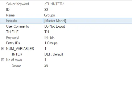
Fig: Output Request.
14. Run the model checker and check for errors. The error of material property appeared which can be omitted. Run the simulation with 4 threads.
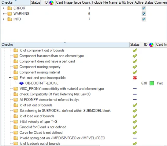
Fig: Model Checker.
RESULT AND DISCUSSION:
Energy Error and Mass error:
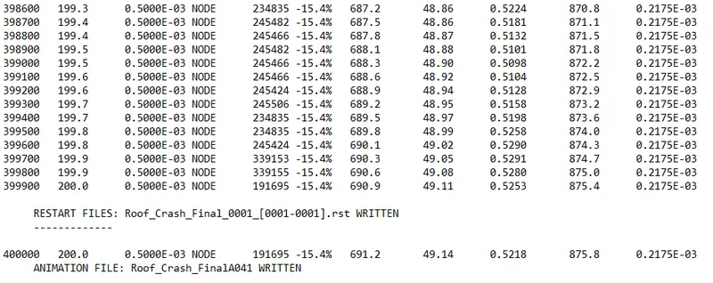
The enegy error on the model varied between 0% to -15.4% but the maximum of -19.9% since the energy is in negetive the energy is dissipated which can be accepted since the analysis is quasi static. The maximum mass error is found to be 0.02175% which is negligible and below 2% and can be accepted.
Resultant force:
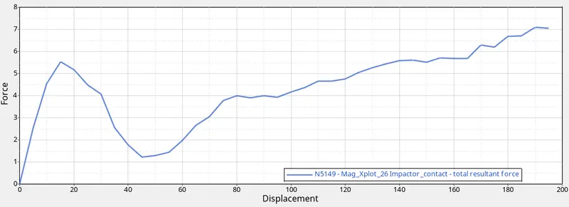
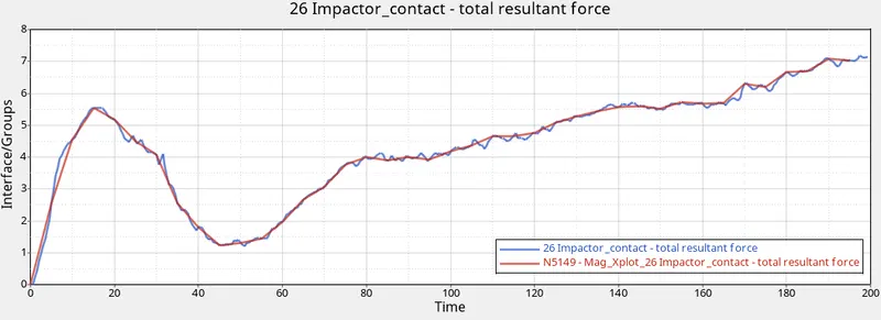
The maximum force restrained by the car was around 5.5KN which is much lesser than the targeted force of 47KN. According to FMVSS 216 the 47KN = 3*GVW (Gross vehicle weight). which means the car gross weight is 1597 Kg (Weight of the full model). The SWR must be above 2.5 which means the resisting force must be 2.5 or 3 times the GVW of the car below which considered as the failure and unsafe. But in this case the SWR is around 0.35 which is very less because of the reduced model.
Target SWR = 47000/1597*9.81 = 3
Obtained SWR = 5500/1597*9.81 = 0.35
The roof will fail under the applied load due to the reduction of the full sized model.
Energy:
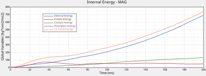
Since the Anlysis is quasi static the energy will increase gradually unlike the dynamic analysis. The hourglass energy is negligible and the internal energy and total energy increses as the diplacement occurs gradually.
Von Mises stress:
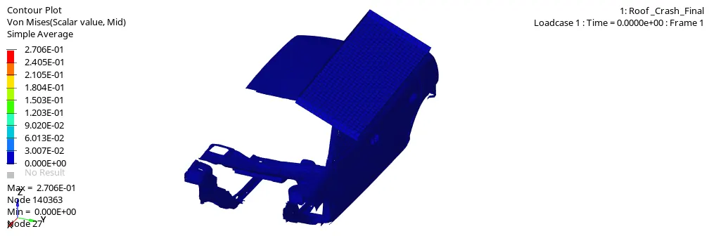
The maximum stress induced in the car is about 0.2706 kg/mm2. the stress values are very less since the analysis is a quasi static.
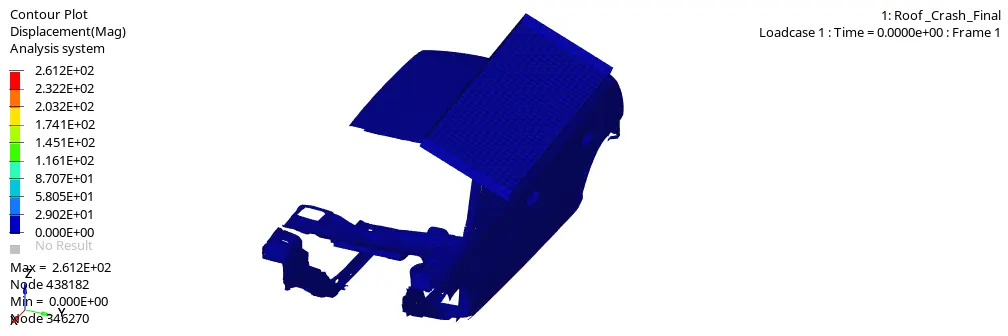
The maximum displacement found on the car is 261.2mm. According to FMVSS the total displacemet can be limited to 5 inches (127mm) at maximum of 568KN. while comparing the displacement is huge for the applied load because of the reduced model.
CONCLUSION:
- While comparing the results with the FMVSS standard the difference in the strength will lead to the failure of the roof structure because of lack of full sized model.
- The SWR (Strength to weight ratio) is very less and Displacement is huge because the function curve values in the Imposed displacement is huge.
- The energy and mass error, Hourglass energy will fall under acceptable level which makes the analysis considerable.