Roof challenge
DESIGN & DRAFT ANALYSIS OF ROOF.
Objective
1. To Design roof including its roof rails for an automotive with the help of given master sections.
2. Do a Curvature study & perform calculations to determine the position of the bow roofs.
3. To perform a Draft Analysis for the entire roof and its components.
Introduction
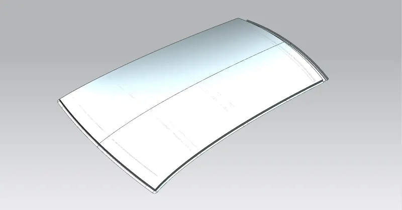
The roof of the Automobile is also known as the top which is located over the passenger compartment. Roof mainly protects the passengers against sun, rain, wind & dust etc.
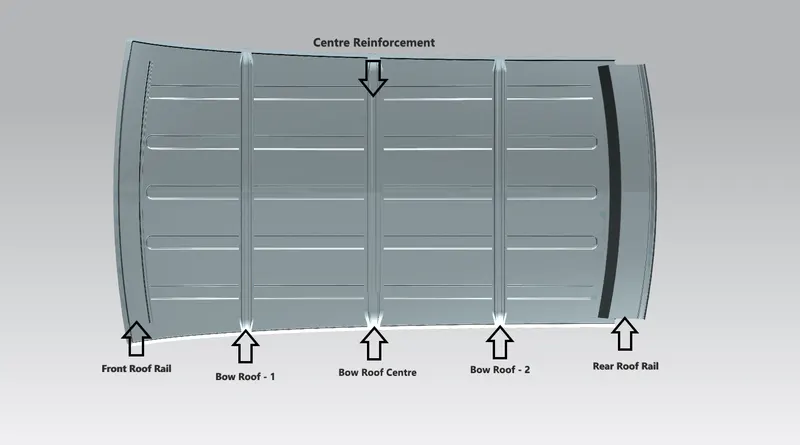
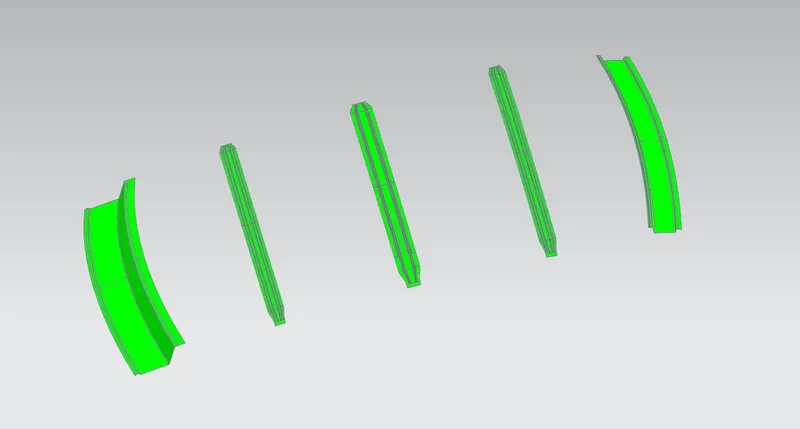
Roof rails act as a support for the roof outer part. The design of front roof rail, two bow roofs, centre roof rail & rear roof rail with the help of the given master sections.
Main Components of roof are
Roof Outer
Front Roof Rail
Bow Roofs
Bow Roof Centre & Reinforcement Centre
Rear Roof Rail
Roof Outer
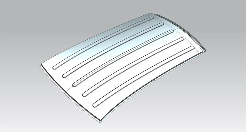
Roof outer part is the major styling portion of the assembly made up of sheet metal. Roof outer panel mainly protects from external objects and abnormal environmental conditions. All the pillars are spot welded around the roof & roof rails. Welding on upper surface is avoided for the best asthetic look.
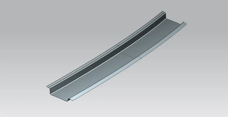
Front Roof Rail
The front roof rail acts as frontal support for the roof and joined with the frontal windshield glass. This is joined with the help of Mastic Sealants.
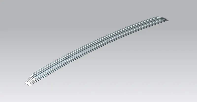
Bow Roof
Bow roofs are used in the roof assembly to improve the strength at a specific region. These bow roofs are joined directly to the roof with the Mastic Sealants.
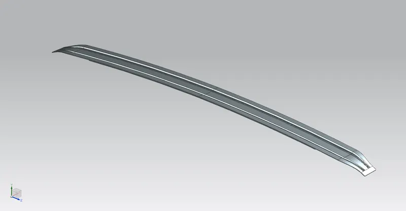
Bow Roof Centre & Reinforcement Centre
Bow roof centre & Reinforcement centre acts as a cross member at the centre of the roof. The centre roof rail is joined to the roof with the mastic sealants. The reinforcement centre & Bow roof centre are joined either with the spot welds or mastic sealants.
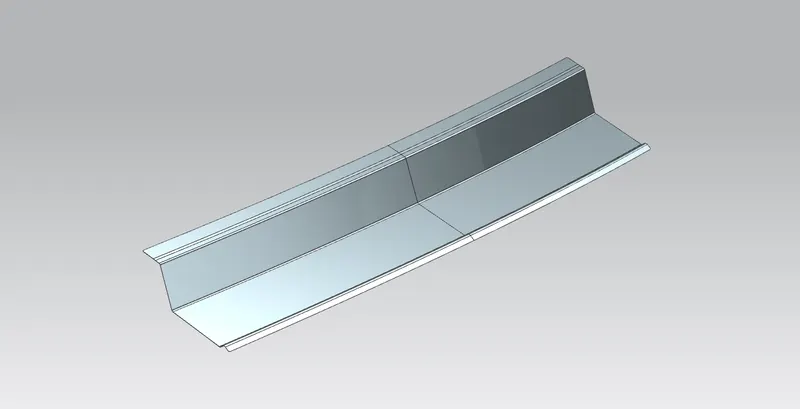
Rear Roof Rail
The rear roof rail acts as support at the rear end of the roof. It is joined to the back door. The rear roof rail is designed according to the inputs taken from the back door. So that it should have headroom clearance and rear visibility criteria.
It is joined with spot welding at the back door side & Mastic sealants are used at the roof's end.
Calculations
Heat Distortion Study
Heat Distortion study plans vital role in sheet metal. Heat distortion temp is known as the temperature limit above which the material can't be used for structural applications.
This study gives a prediction about heat distortion temperature. To avoid bends & damages to the designed structure. Heat Distortion study helps us to position the bow roof which strengthens the roof.
Bow – roof prediction Formula
W = [1.73 x 10^(-3) x L] + [1.85 x 10^(-8) x (R^2)/t] + [ 1.10x10^(-3) x l] - 2.68
Judgement Condition : OK< 2.7> 3.1
Where,
L = Roof Length in X-Direction[mm](Roof dimension in 0-Y)
R = Roof curvature
R = 2(Rx*Ry)/(Rx+Ry)
Rx = X curvature
Ry = Y curvature
t = Roof plate thickness [mm]
l = Bow Roof Span [mm]
by calculations
Table 1

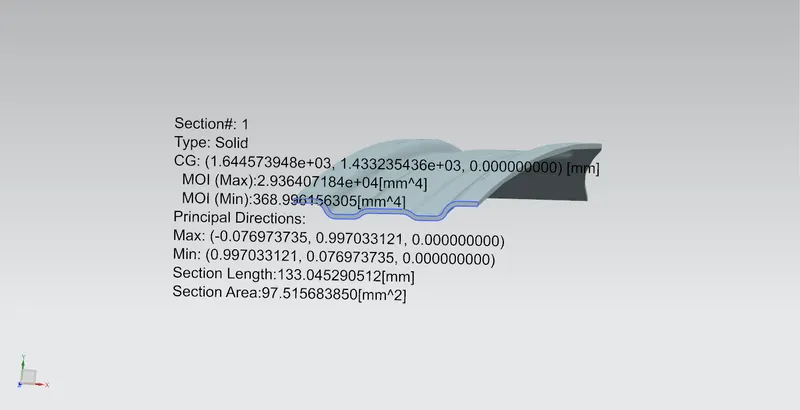
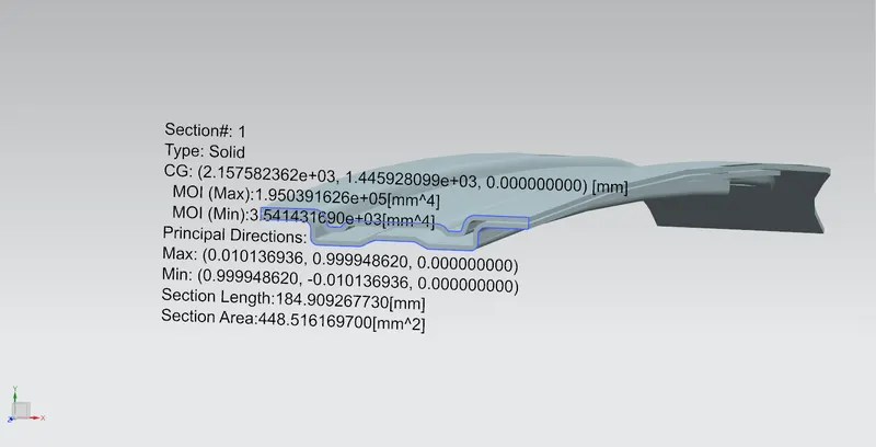
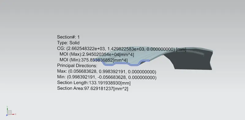
Moment of Inertia (Iy)
Section moment of Inertia used to predict the amount of deformation or deflection of the designed part across the section. Higher moment of inertia is prefered as it reduces the amount of defection occcured by the applied force.
The moment of Inertia (Iy) for all the rail roof is calculated across the section by using a command called section analysis in NX Cad.
Bow Roof Rail 1
Centre Roof Rail & Centre Reinforcement
Bow Roof Rail 2
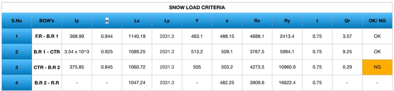
Snow Load Criteria
Snow load criteria is important in justifying the bow roof rail position in snowfall regions. Due to snowfall, snow will get collected on the top of the roof which will tend to bend the roof. The bow roof will be in such a position that will provide more strength to the roof against bending.
Snow load Prediction formula
Qr = [Iy x t2] / [α x s x [(Rx + Ry)/2]2 x 10-8]
Note: The Qr value given over here is correct. There was a typo error in the formula given in the video.
Where,
α = My x Lx2 x 10-12 , My = Y(Ly-Y)
Judgement condition - Qr ≥ 3.1
250 ≤ s ≤ 380.
t = Roof plate thickness [mm]
Ly = Distance between the front and rear roof Rails on the Vehicle along with 0Y[mm]
Length of Roof panel with the centre point between Roof rail Front /Rear as the reference point of the front and the rear.
Lx = Distance between the Left and Right end of the roof on the Roof BOW [mm]
Width of the roof panel exposed on the surface.
Y = Distance front Front Roof Rail to Roof BOW[mm]
s = Distance for which Roof BOW bears divided load [mm]
s = L1/2 + L2/2
Iy = Geometrical moment of inertia of Roof BOW (Y cross-section )[mm4]
Rx = Lateral direction curvature radius of roof panel Y cross-section on Roof BOW [mm]
Roof panel curvature Radius of the Length Lx in Front view
Ry = Longitudinal Direction curvature radius of the Roof panel X cross-section on Roof BOW [mm]
Roof panel X curvature radius of lengths in Side view
by calculations,
Table 2
Draft Analysis
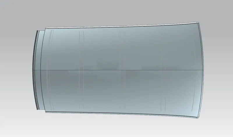
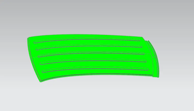
Draft Analysis is made to check if the designed component does not process any negative draft. Because negative drafts may create issues during the manufacturing process. Sheet metal parts should have a draft of at least 7 degrees for proper tooling.
Conclusion
As per heat distortion criteria, all the bow roofs are in the right positions.
But, as the snow load criteria values of Qr < 3.1, so to compensate that embosses are added on the roof outer body.