Assembly of Yacht
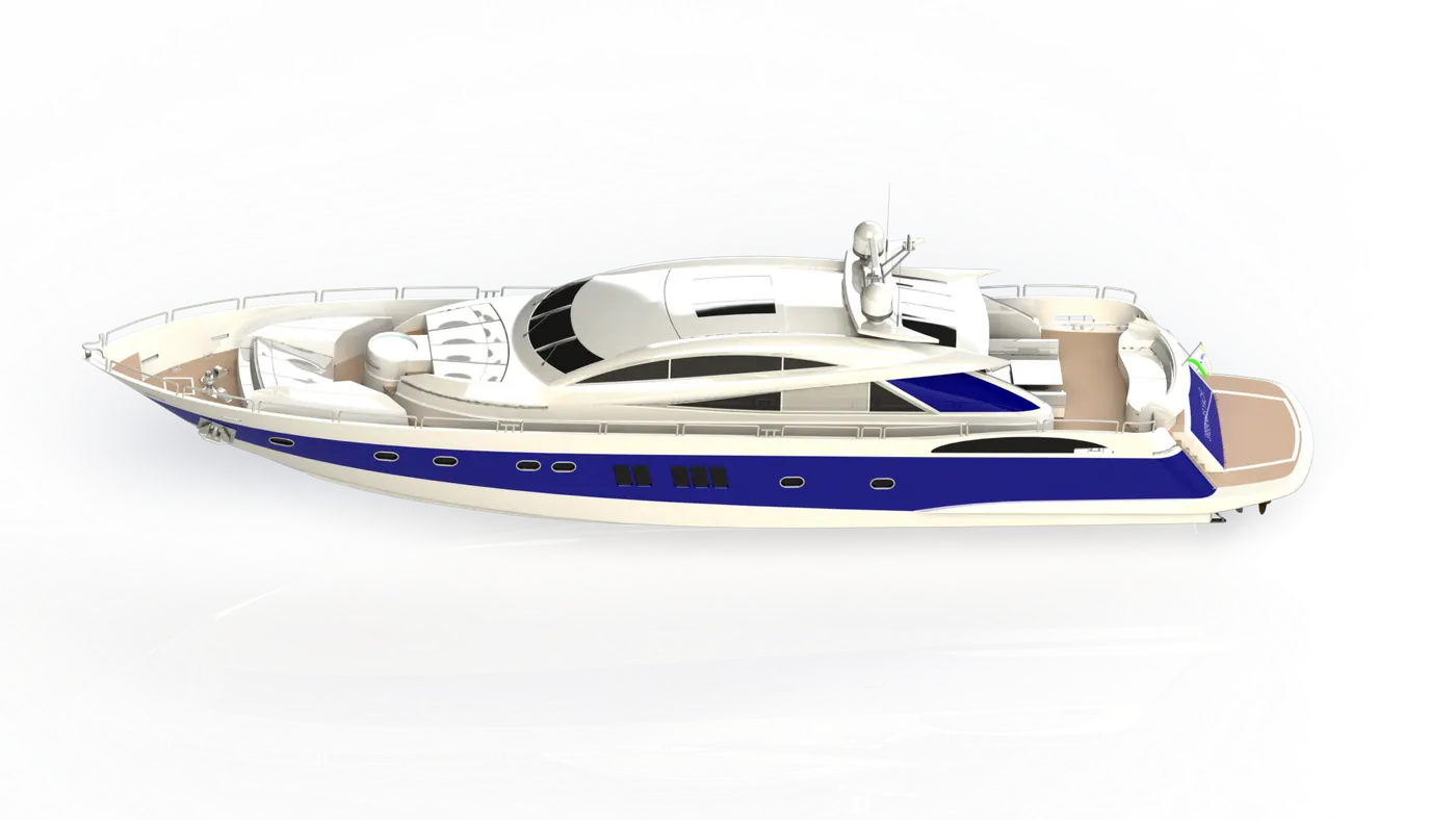
Modelling, Assembly and Photo Realistic Rendering of Yacht.
Objective
• Designing of various parts of Yacht using Solidworks.
• Assembly of all the designed parts, to create Yacht.
• Make the Photo Realistic Rendering of the Yacht Model.
Introduction
• Main aim is to design different parts of Yacht using, various tools and commands in Solidworks.
• Assembling of all the parts, which collectively makes the desired Yacht model.
• Creating the Photorealistic Envinornment, to the designed yacht model by using various commands of Photoview 360 and Solidworks Visualize.
Flowchart
Modelling
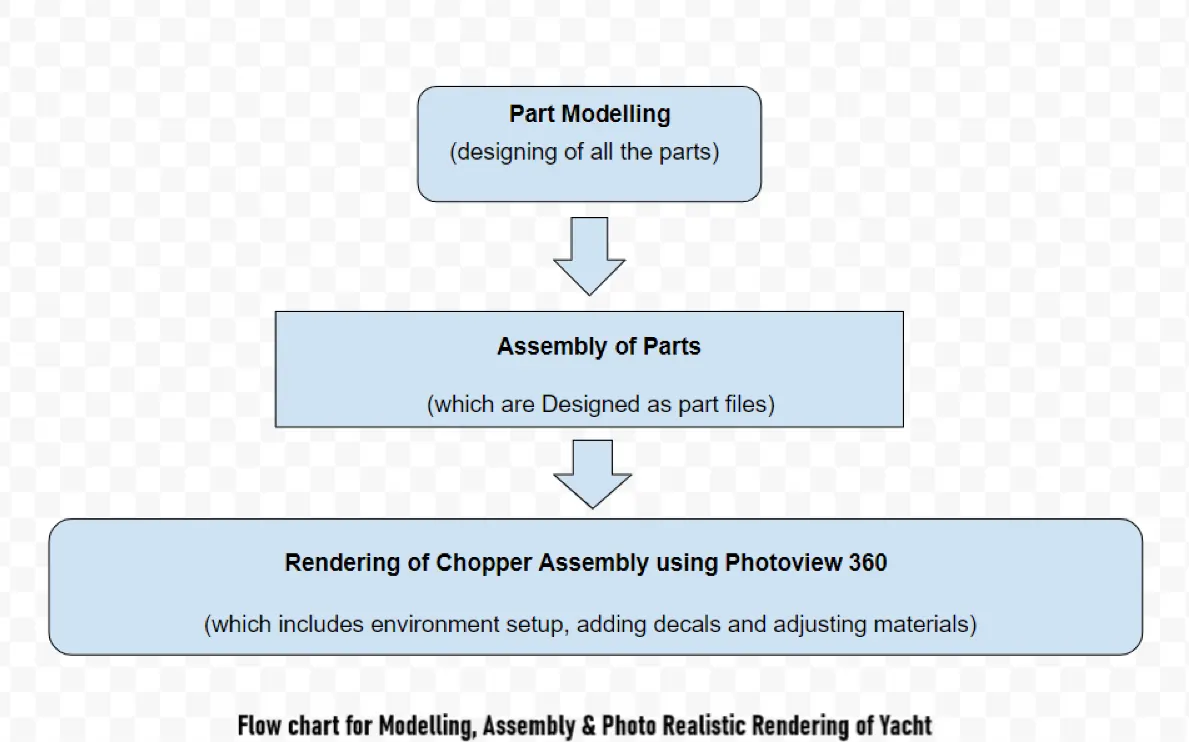
All parts can be designed, by drawing 2D Sketch in a plane and converting the sketch into required 3D Model by usage of appropriate commands.
Components of Yacht
The following components must be designed as part files, in order to create the assembly of the Yacht.
⦁Propeller
⦁Radar
⦁Hull
⦁Garage Door
⦁Front Seat
⦁Middle Seat
⦁Rear Seat
⦁Super Structure
⦁Radar Mast
Propeller
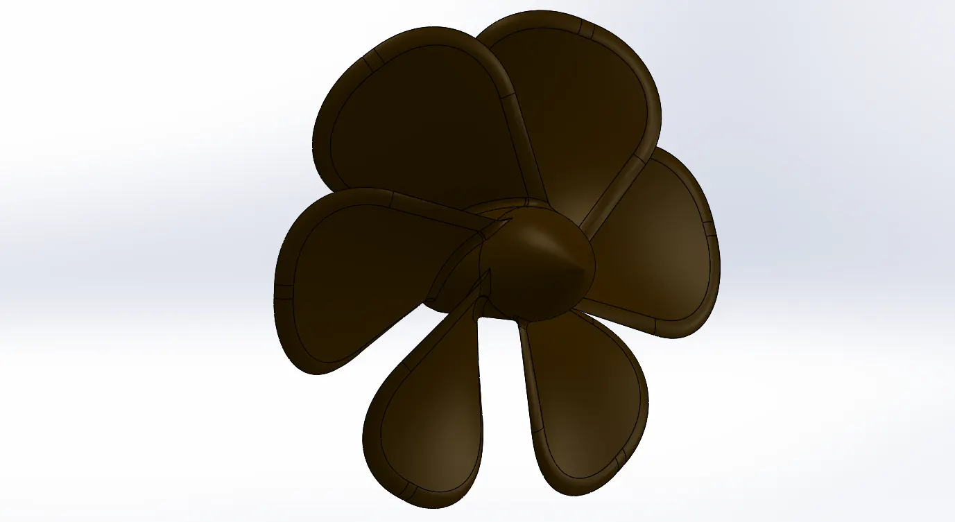
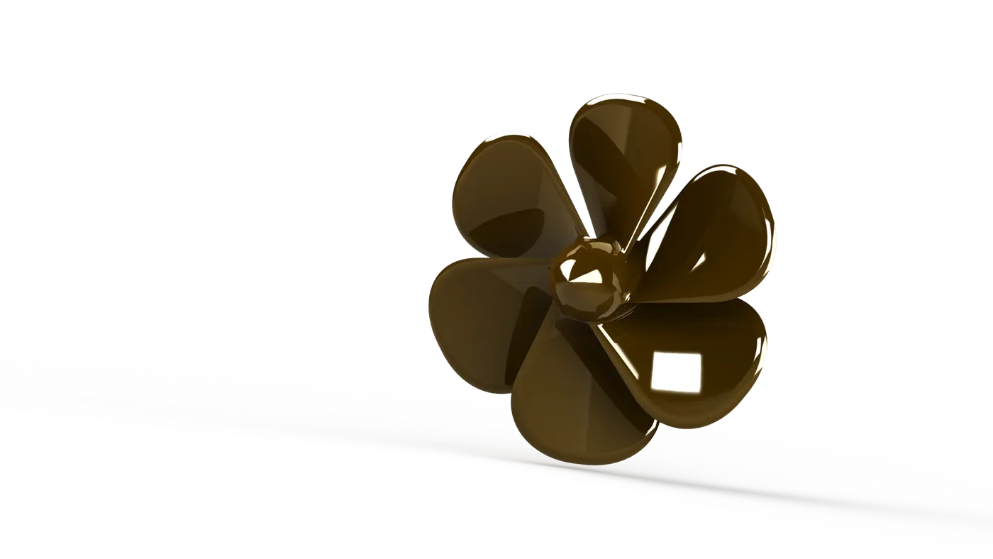
A propeller is a device with a rotating hub and radiating blades that are set at a pitch to form a helical spiral, that, when rotated, performs an action which is similar to Archimedes' screw. It transforms rotational power into linear thrust by acting upon a working fluid, such as water or air.The rotational motion of the blades is converted into thrust by creating a pressure difference between the two surfaces. A given mass of working fluid is accelerated in one direction and the craft moves in the opposite direction.
There are various sub-features available inside every feature, we have use them according to our requirement or necessity.
Features used
⦁Sketch
⦁Revolve
⦁Plane
⦁Loft
⦁Fillet
⦁Cut Extrude
⦁Circular Pattern
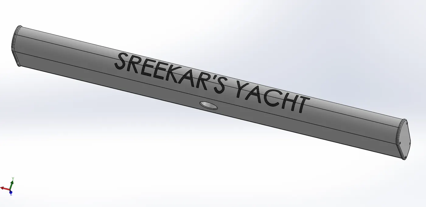
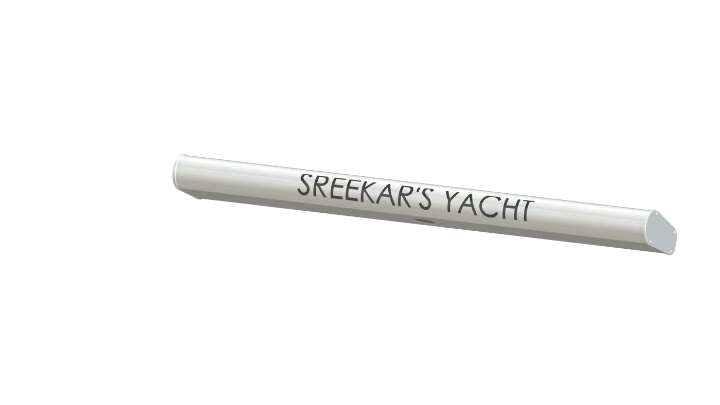
Radar
Marine radars used to detect other ships and land obstacles, to provide bearing and distance for collision avoidance and navigation at sea. They are electronic navigation instruments that use a rotating antenna to sweep a narrow beam of microwaves around the water surface surrounding the ship to the horizon, detecting targets by microwaves reflected from them, generating a picture of the ship's surroundings on a display screen.
Features used
⦁Sketch
⦁Boss Extrude
⦁Fillet
⦁Cut Extrude
⦁Sketch Pattern
⦁Mirror
⦁Spline
Hull
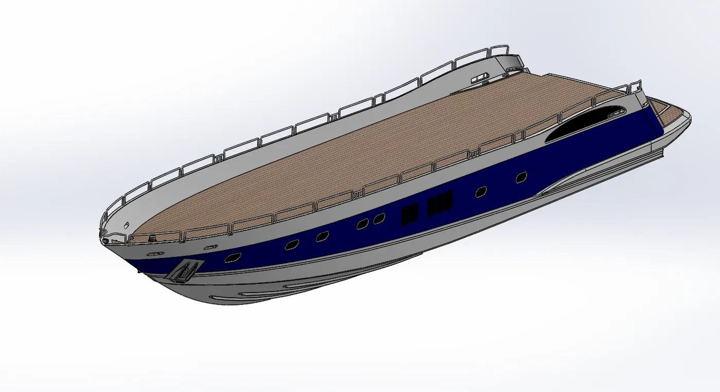
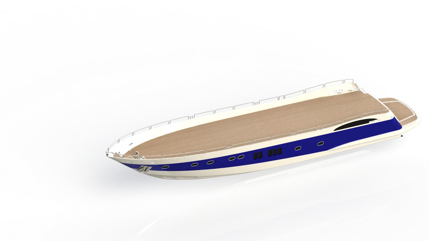
A hull is the watertight body of a ship or boat. The hull may open at the top, or it may be fully or partially covered with a deck.
The hull of a ship is the most notable structural entity of the ship. To define the hull, it can be said that it is the watertight enclosure of the ship, which protects the cargo, machinery, and accommodation spaces of the ship from the weather, flooding, and structural damage.
Features used
⦁Sketch
⦁Curve
⦁Surface Loft
⦁Surface Trim
⦁Surface Extrude
⦁Surface Knit
⦁Surface Fill
⦁Shell
⦁Cut Extrude
⦁Fillet
⦁Chamfer
⦁Plane
⦁Sweep
⦁Boss Extrude
⦁Cut Extrude
⦁Dome
⦁Revolve
⦁Helix/Spiral
⦁Sweep
⦁Linear Pattern
⦁Curve
⦁DeleteFace
⦁Extrude Thin
⦁Cut Extrude Thin
⦁Split
⦁Split Line
⦁Mirror
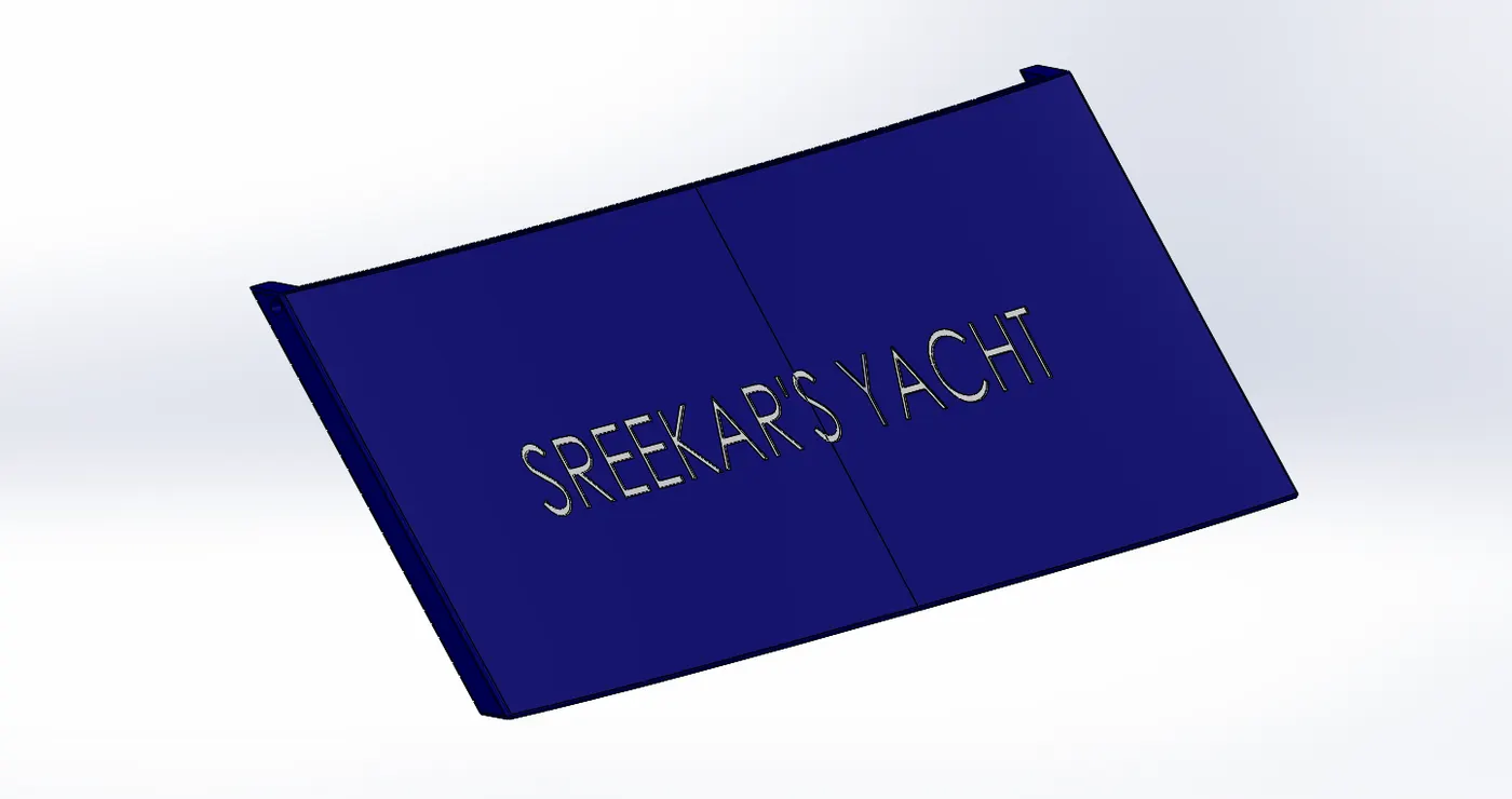
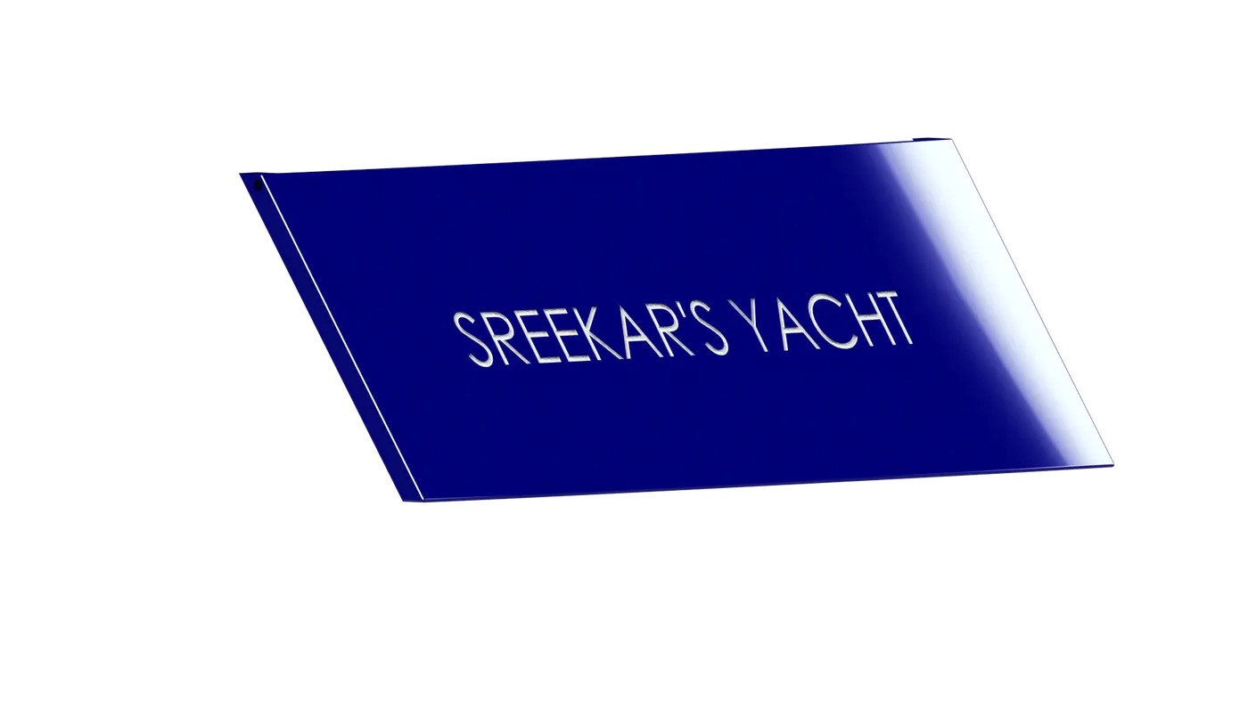
Garage Door
A garage door is a large door on a garage that opens either manually or by an electric motor. Garage doors are frequently large enough to accommodate automobiles and other vehicles.
Even that space can be used to accomidate many other materials.
Features used
⦁Sketch
⦁Cut Extrude
⦁Shell
⦁Fillet
⦁Plane
⦁Mirror
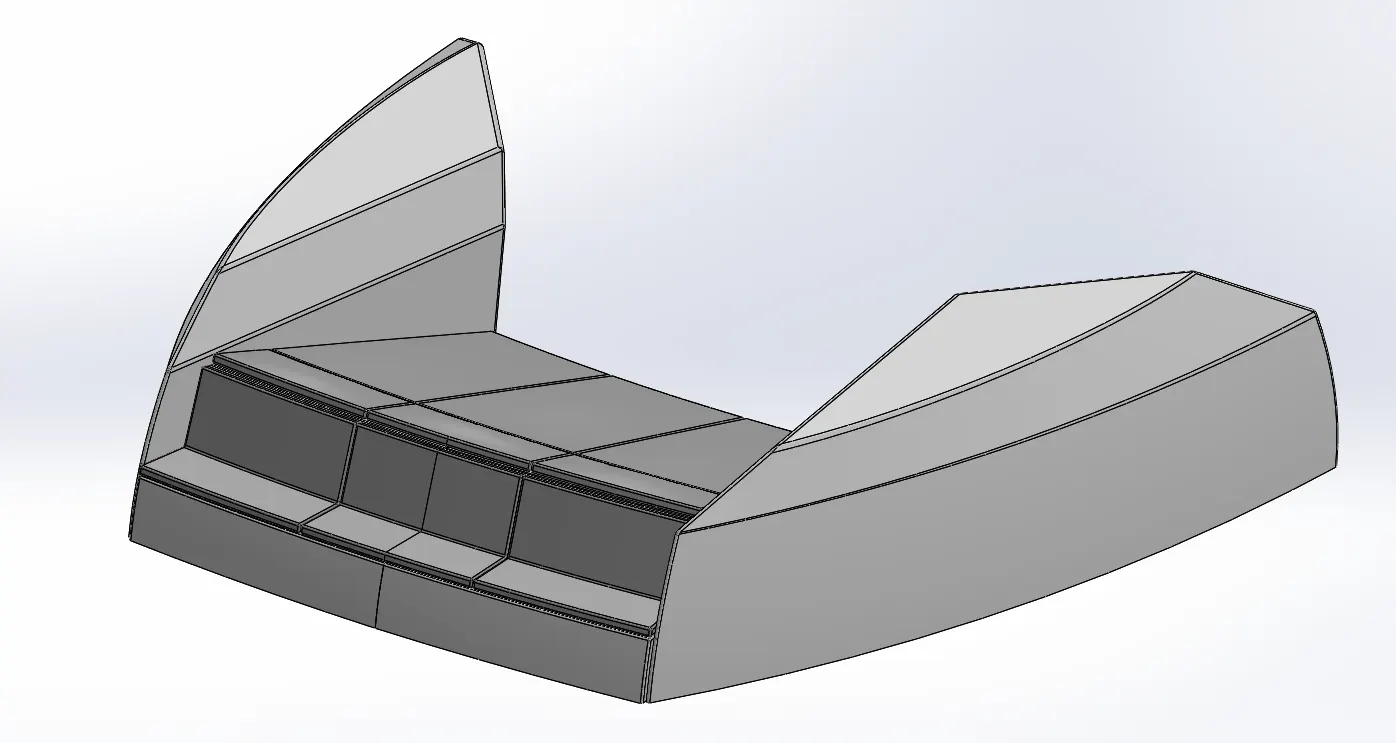
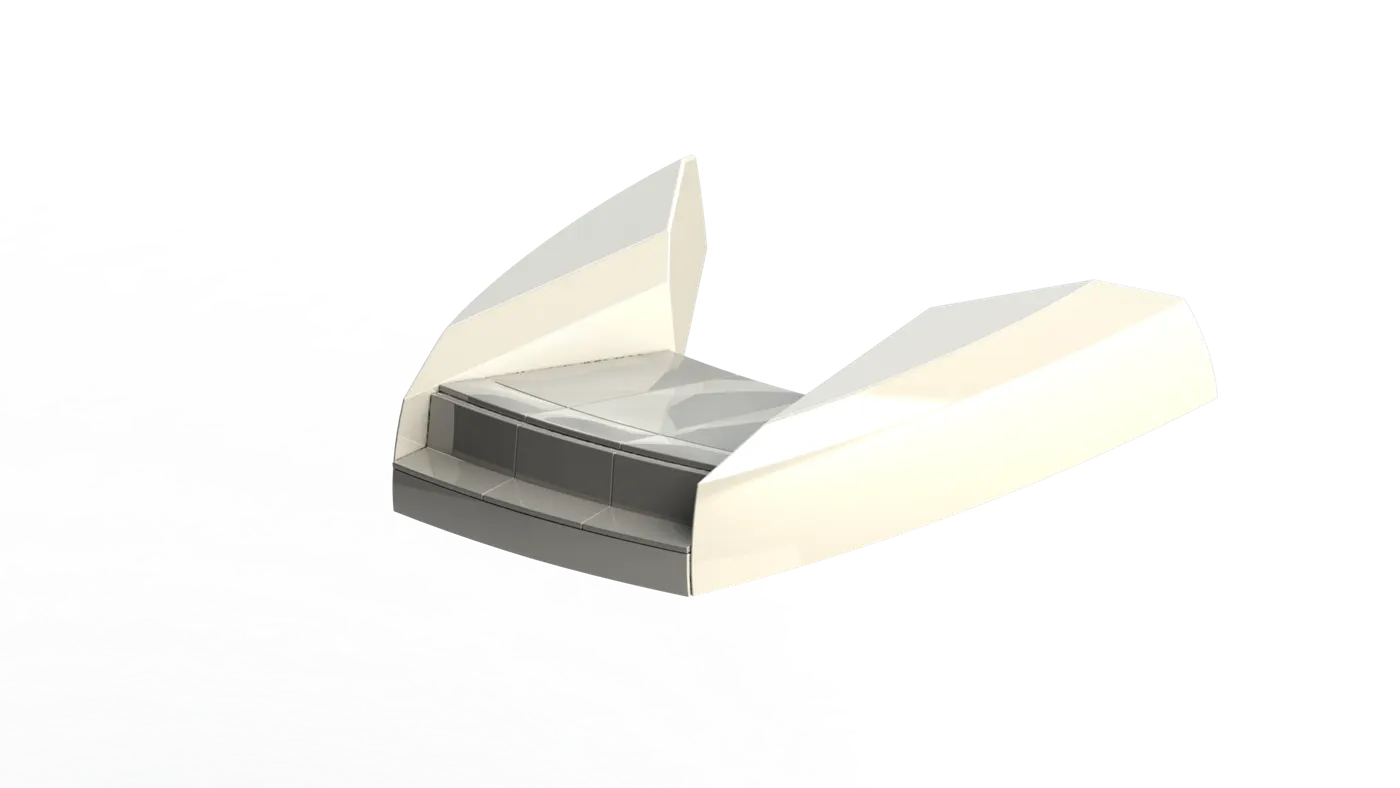
Front Seat
Front seat is located infornt of the super structure, generally used to rest. In the Luxury Yachts Front seat is very essential to enjoy the view.
Features used
⦁Sketch
⦁Plane
⦁Surface Sweep
⦁Surface Extrude
⦁Surface trim
⦁Surface Fill
⦁Surface Loft
⦁Surface Knit
⦁Chamfer
⦁Revolve
⦁Cut Extrude
⦁Cut Extrude Thin
⦁Fillet
⦁Mirror
⦁Dome
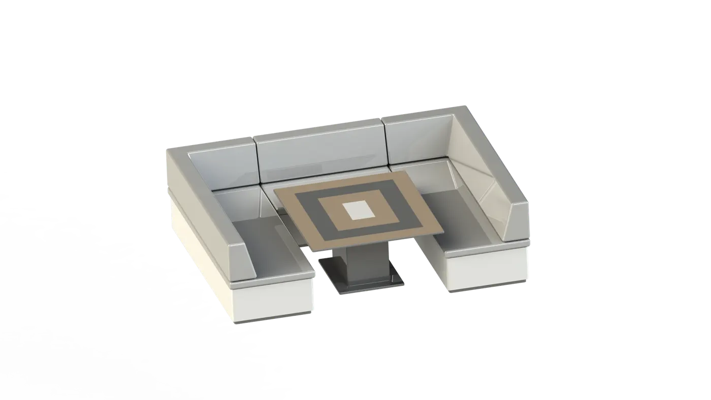
Middle Seat
Middle seat is located behind the super structure, generally used for sitting and dining.
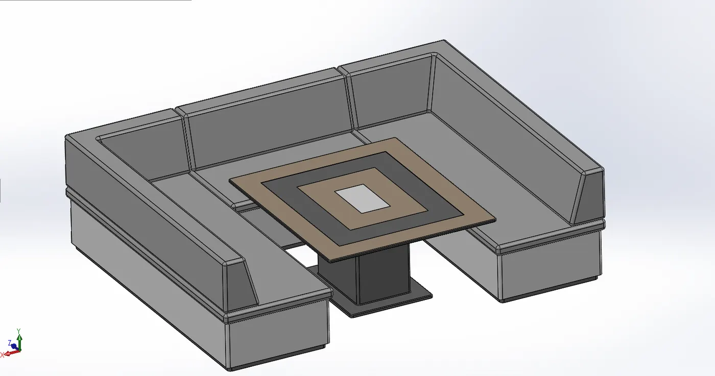
Features used
⦁Boss Extrude
⦁Plane
⦁Chamfer
⦁Fillet
⦁Mirror
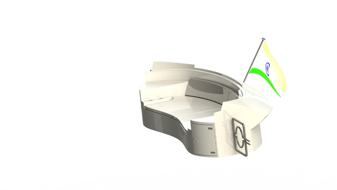
Rear Seat
Middle seat is located behind the super structure and placed at the edge of hull part , generally used for sitting and enjoying the view.
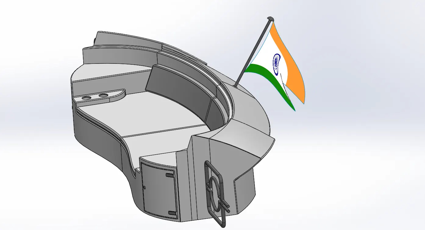
Features used
⦁Plane
⦁Surface Sweep
⦁Surface Offset
⦁Surface Trim
⦁Ruled Surface
⦁Surface Knit
⦁Surface Extend
⦁Surface Extrude
⦁Surface Loft
⦁3D Sketch
⦁Boss Extrude
⦁Cut Extrude
⦁Chamfer
⦁Fillet
⦁Delete Face
⦁Sweep
⦁Mirror
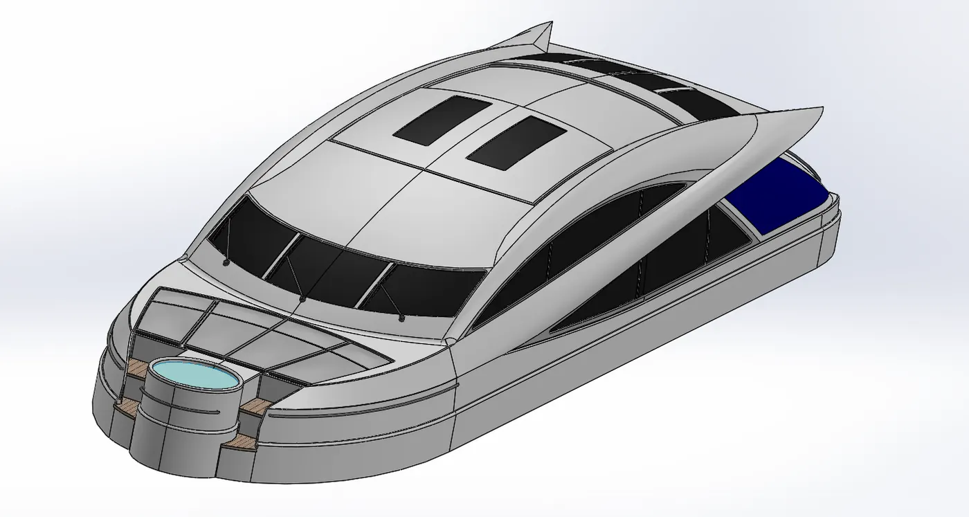
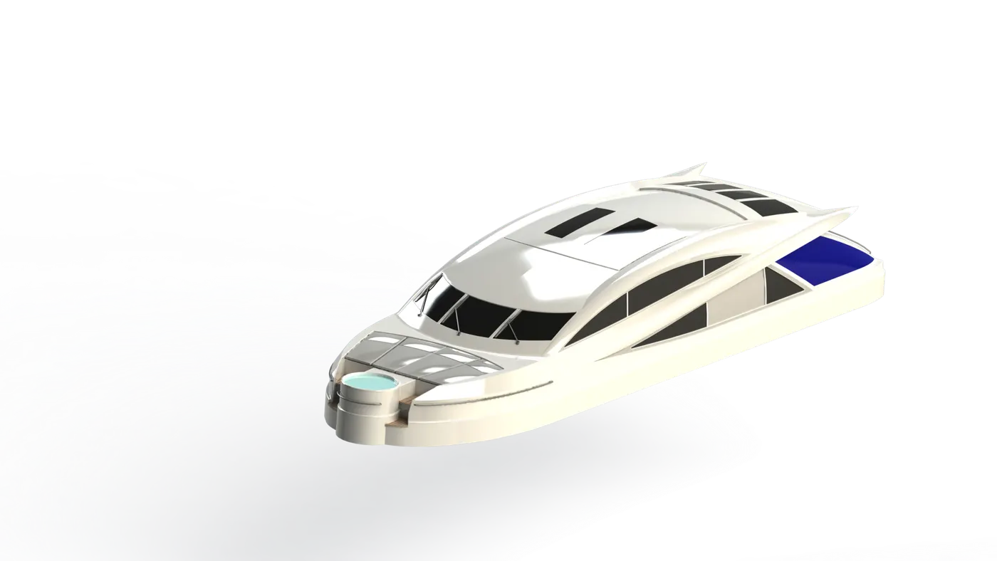
Super Structure
A superstructure is an extended construction of any building or platform that rises above the rest of the building or platform in a distinct manner.
Superstructure means to add a construction to an already existing structure. In ships this is the name given to the part of the ship that emerges from the deck.
The size of the superstructure has a great influence on the mobility of the vessels. They are designed in a manner, so that, they add value and hinder the speed and mobility in the least. The superstructure is mostly designed in fashion as well. This is because it is the most easily visible part of the ship, in fact it is the identification of the ship, and so the designers try to provide it with the identity that is unique.
Features used
⦁Sketch
⦁Surface Extrude
⦁Plane
⦁Surface Sweep
⦁Surface Knit
⦁Fillet
⦁Ruled Surface
⦁Surface Thin
⦁Curve
⦁Surface Loft
⦁Surface Fill
⦁3D Sketch
⦁Surface Extend
⦁Delete face
⦁Boss Extrude
⦁Surface Offset
⦁Thicken
⦁Cut Extrude
⦁Dome
⦁Sweep
⦁Extrude Thin
⦁Split Line
⦁Mirror
⦁Chamfer
Radar Mast
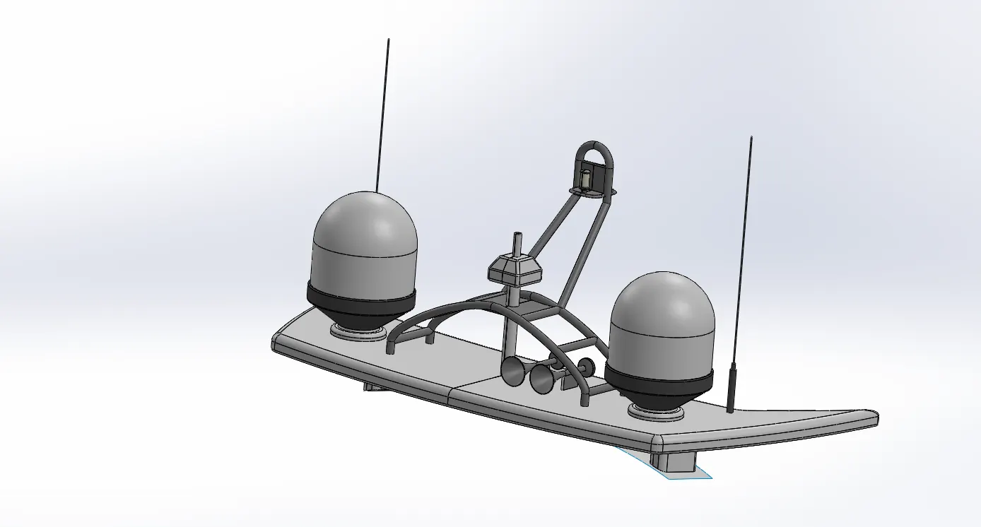
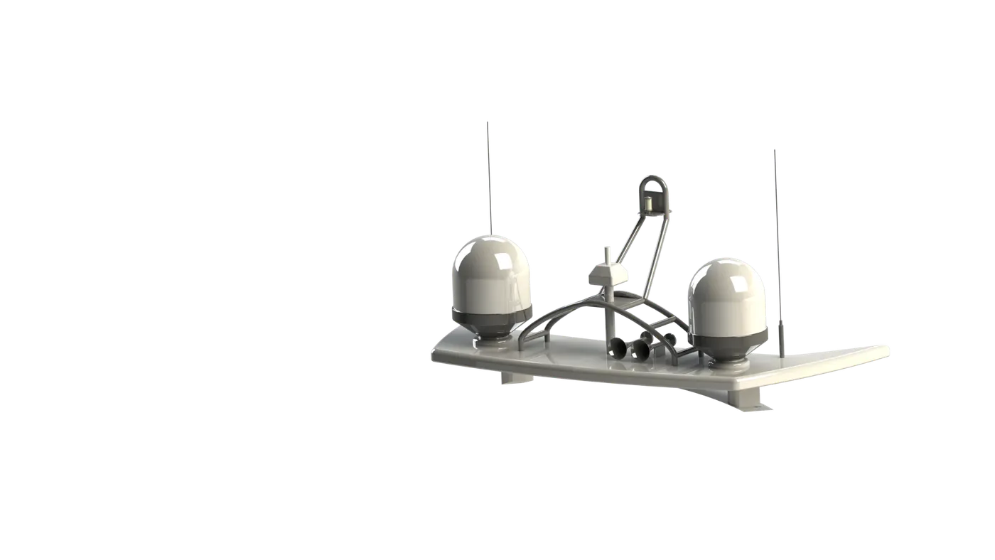
The Radar mast supports the radar, antennas, sattilite domes and lights.
Features used
⦁Sketch
⦁Plane
⦁Boss Extrude
⦁Fillet
⦁Revolve
⦁Sweep
⦁Mirror
⦁Curve
⦁Chamfer
⦁Dome
⦁Shell
ASSEMBLY OF YACHT
Assembly
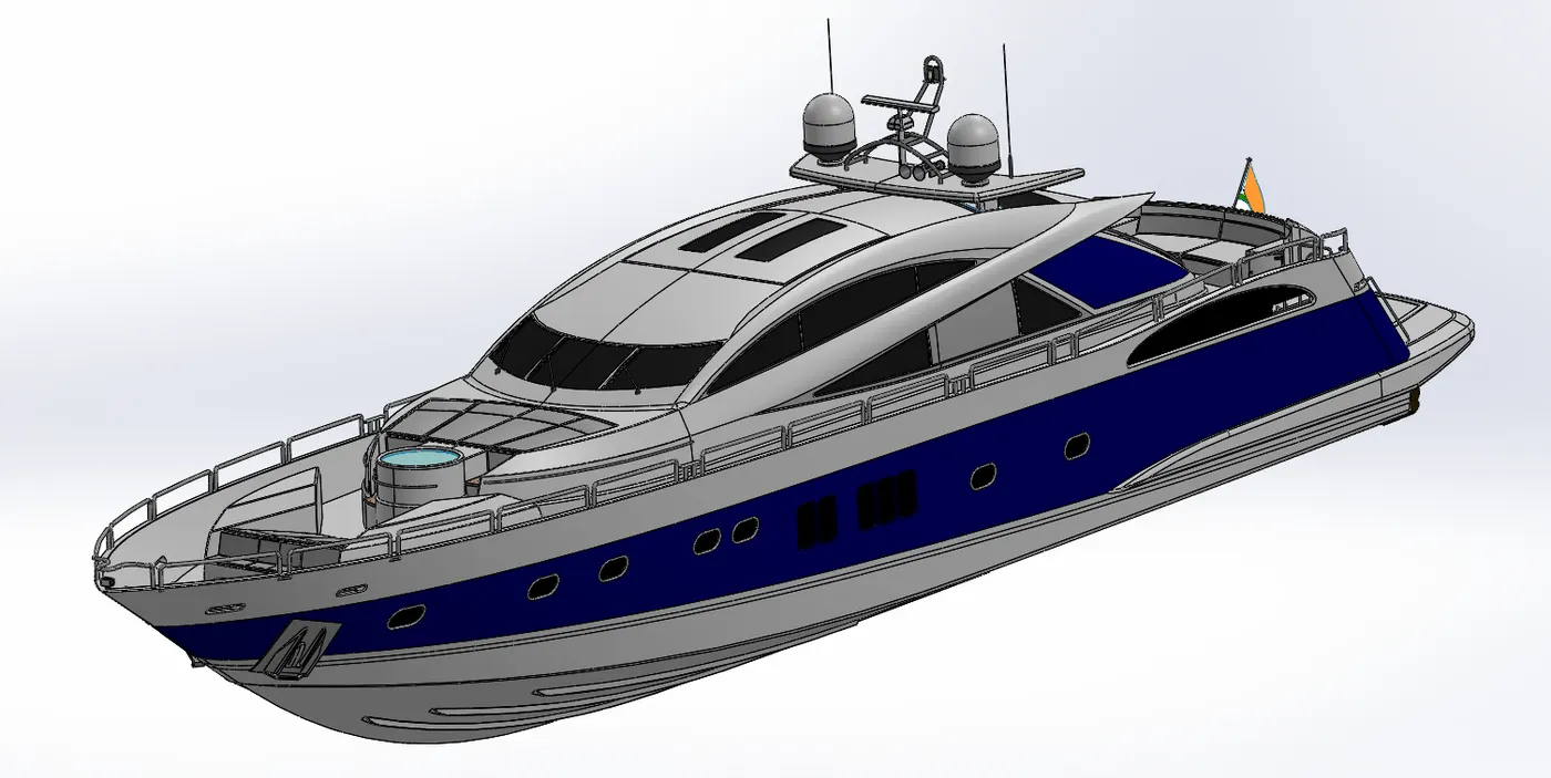
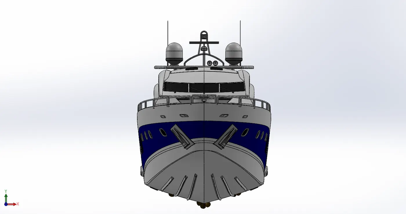
At first, the Hull part file is inserted in the assembly by using insert parts option. After insertion of the Hull part file in the assembly we need to fix Hull in the assembly environment.
Now we can insert all the Yacht parts one by one by applying the mate conditions between the Hull and other parts.
Features used
⦁ Insert Part
⦁ Mates
Insert Part
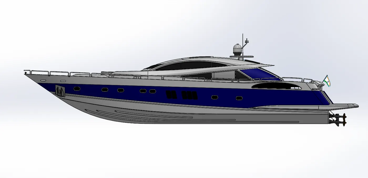
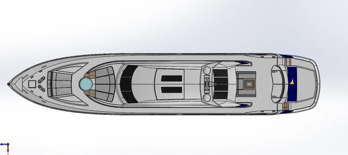
We can insert the designed parts of the Yacht one by one to make the assembly.
Mates
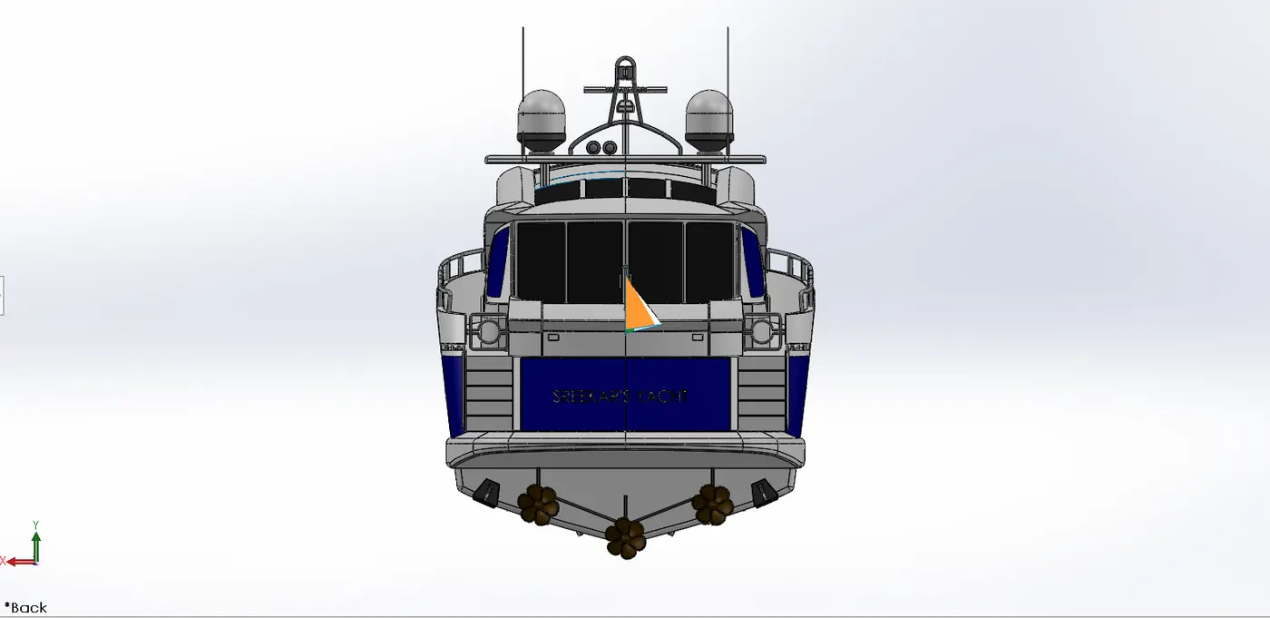
Mates create geometric relationships between assembly components. As you add mates, you define the allowable directions of linear or rotational motion of the components. You can move a component within its degrees of freedom, visualizing the assembly's behaviour.
For Example,
A concentric mate forces two cylindrical faces to become concentric. The faces can move along the common axis, but cannot be moved away from this axis.
A coincident mate forces two planar faces to become coplanar. The faces can move along one another, but cannot be pulled apart.
Mates are solved together as a system. The order in which you add mates does not matter; all mates are solved at the same time. You can suppress mates just as you can suppress features.
RENDERING
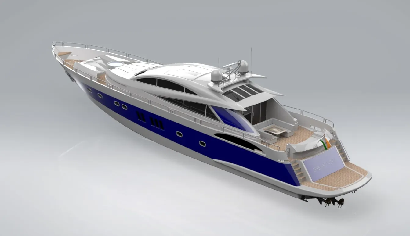
Rendering creates the photorealistic image of the designed model with a realistic environment.
Rendering can be done with the help of Photo-view 360 and Solid works Visualize.
PhotoView 360 is a SolidWorks add-in that produces photo-realistic renderings of SolidWorks models. The rendered image incorporates the appearances, lighting, scene, and decals included with the model. PhotoView 360 is available with SolidWorks Professional or SolidWorks Premium.
CONCLUSION
All the parts of the Yacht are designed, then all of them are inserted in the assembly environment by applying mates to achieve the desired Assembly of the Yacht.
The Assembly of the Yacht is rendered by using Photoview 360 and Solidworks Visualize.