Photo Realistic Rendering
Modelling, Assembly and Photo Realistic Rendering of American Chopper.
Objective
• Designing of various parts of chopper using Solidworks.
• Assembly of all the designed parts, to create chopper.
• Make the Photo Realistic Rendering of the Chopper Model.
Introduction
• The main moto is to design different parts of chopper using, various tools and commands in Solidworks.
• Assembling of all the parts, which collectively makes the desired chopper model.
• Creating the Photorealistic Envinornmrent, to the designed chopper model by using various commands of Photoview 360 and Solidworks Visualize.
Flowchart
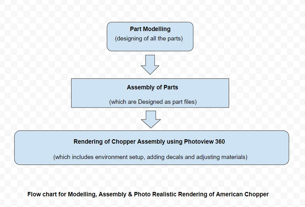
Modelling
All parts can be modelled, by drawing 2D Sketch in a plane and converting the sketch into required 3D Model by usage of appropriate commands.
Components of chopper
The following components must be designed as part files, in order to create the assembly of the chopper.
• Transmission Belt
• Kick Stand
• Front Fender
• Rear Fender
• Oil Tank
• Chain
• Pedal
• Front Wheel
• Rear Wheel
• Front Fork
• Chassis
• Engine
• Gas Tank
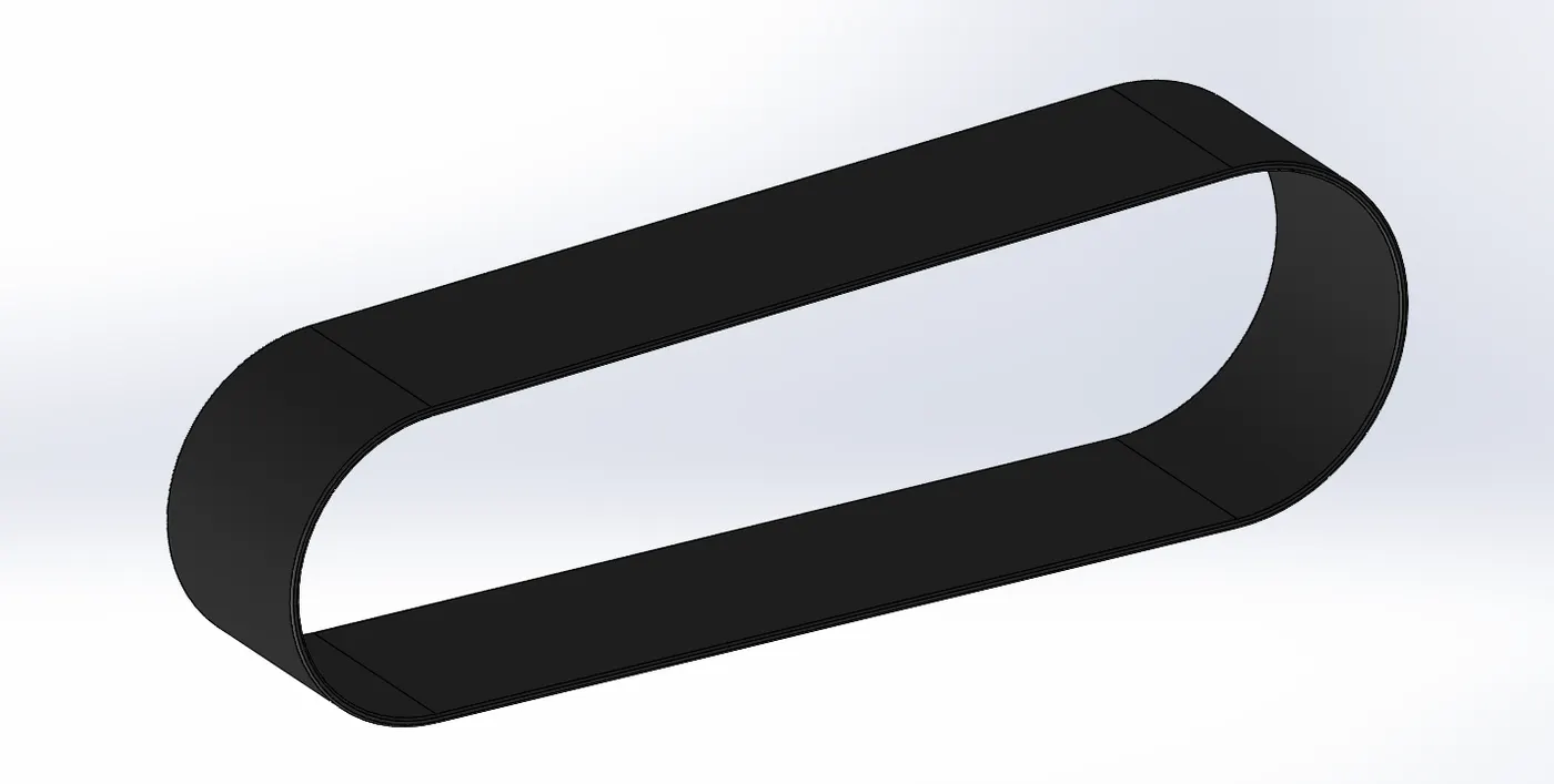
⦁ Transmission Belt
Belt is used to transmit rotary motion between two parallel shafts. Transmission Belt transmit the power from Engine to the Gearbox.
Features used
⦁ Sketch
⦁ Offset
⦁ Extrude
⦁ Fillet
⦁ Appearances
There are various sub-features available inside every feature, we have use them according to our requirement or necessity.
Sketch
Sketch is a 2D representation of an appropriate part which has to designed. There are various entities that have to use such as line, arc, circle, rectangle, spline etc in order to achieve the desired sketch.
Offset
Offset one or more sketch entities, selected model edges, or model faces by a specified distance. For example, you can offset sketch entities such as splines or arcs, sets of model edges, loops, and so on.
Extrude
Extrude feature is used to convert 2D Sketches into 3D models, there are various sub-options are available in the Extrude feature like thin extrude, offset extrude etc which has to be used out of necessity.
Fillet
Fillet/Round creates a rounded internal or external face on the part. You can fillet all edges of a face, selected sets of faces, selected edges, or edge loops.
Appearances
An appearance defines the visual properties of a model, including colour and texture. Appearances do not affect physical properties, which are defined by materials.
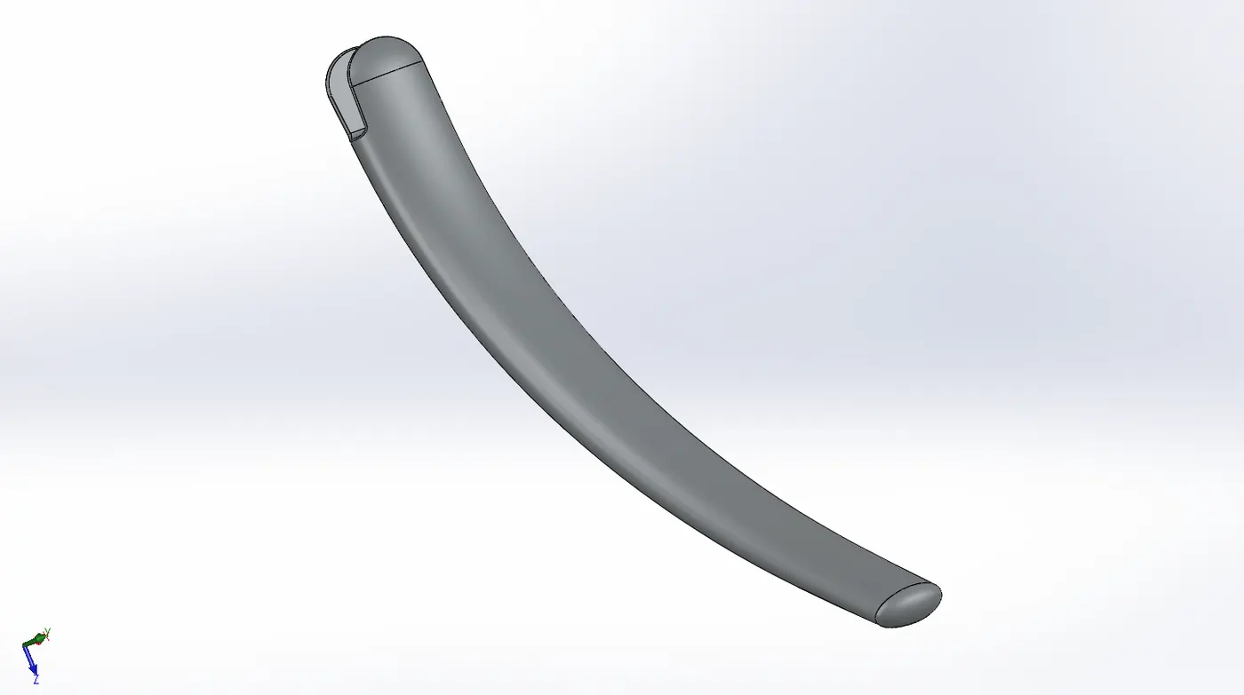
⦁ Kick Stand
A kickstand is a device on a bicycle or motorcycle that allows the bike to be kept upright without leaning. Basically, it is used to maintain firm posture when the bike is parked.
Features used
⦁ Sketch
⦁ Loft
⦁ Dome
⦁ Extrude Boss
⦁ Extrude Cut
⦁ Fillet
⦁ Split
⦁ Appearances
Loft
Adds material between two or more profiles to create a solid feature. The first, last, or first and last profiles can be points. There are various loft profiles like loft surface which creates surface between two or more profiles.
Dome
Adds dome on the selected planar or non-planar surfaces, domes can be created circular or elliptical upon requirement.
Extrude Cut
Extrude cut feature is used to cut a solid model by extruding a sketched profile in one or two directions. We can adjust the bodies which need to be cut, in the dialog box.
Split
Creates multiple bodies from a single selected body. we can create the multiple bodies in the exiting part model or in separate parts.
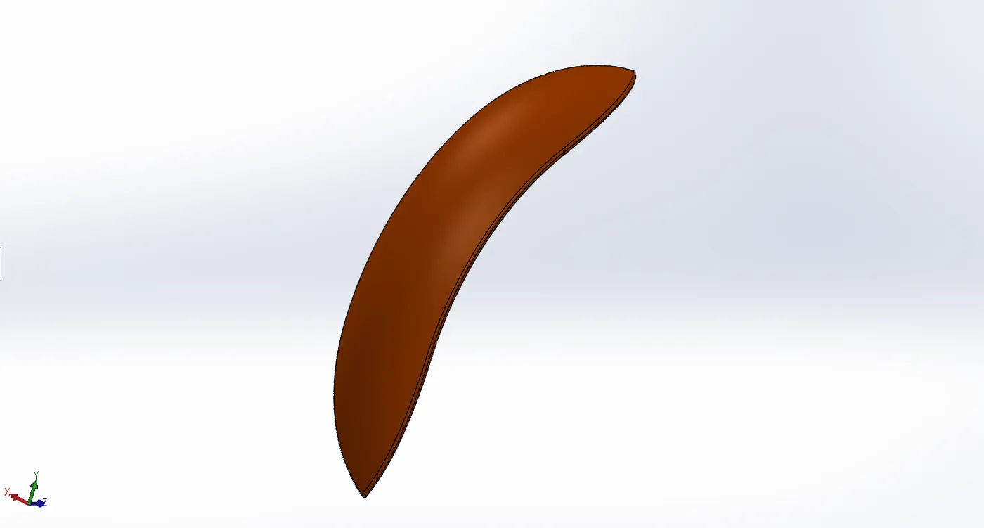
⦁ Front Fender
Fender is the part of an automobile, motorcycle or other vehicle body that frames a wheel well (the fender underside). Its primary purpose is to prevent sand, mud, rocks, liquids, and other road spray from being thrown into the air by the rotating tire.
Features used
⦁ Sketch
⦁ Offset Entities
⦁ Trim Entities
⦁ Revolve Boss
⦁ Split
⦁ Fillet
⦁ Appearances
Offset Entities
Adds sketch entities by offsetting face, edges, curves, or sketch entities a specified distance.
Trim Entities
Trims or extends a sketch entity to be coincident to another, or deletes a sketch entity.
Revolve Boss
Revolves a sketch or selected sketch contours around a selected axis to create a solid feature.
⦁ Rear Fender
Rear fender frames the rear wheel of the chopper.
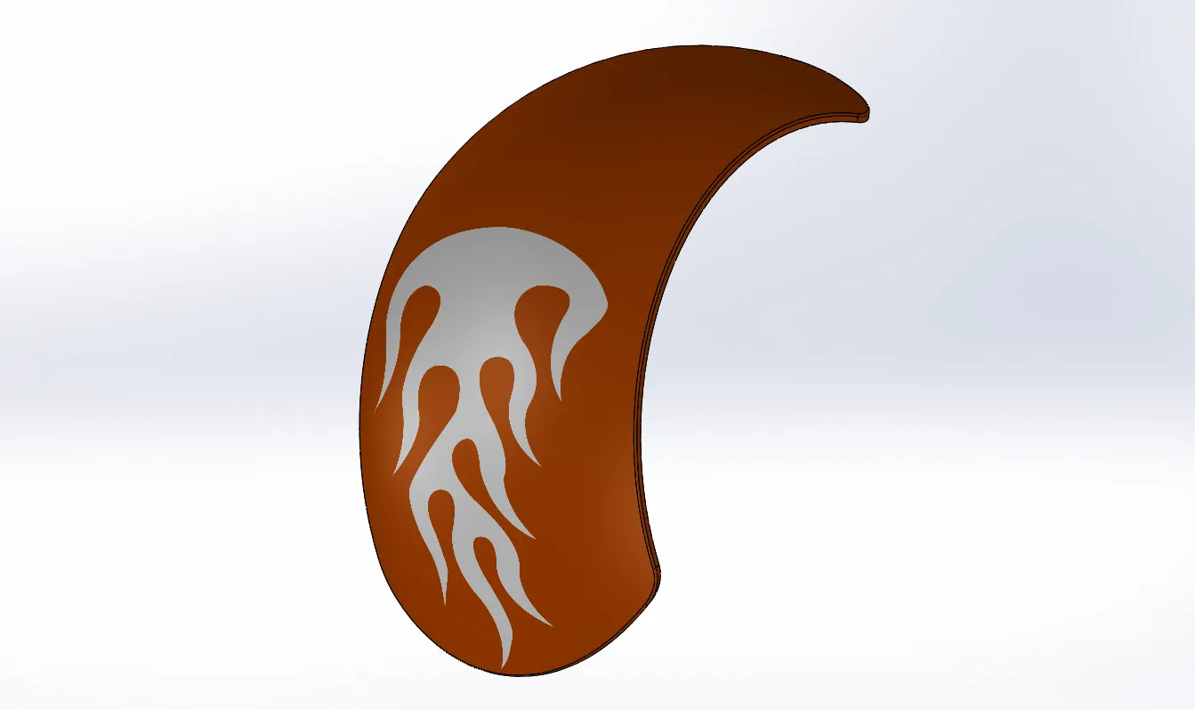
Features used
⦁ Sketch
⦁ Offset Entities
⦁ Trim Entities
⦁ Revolve Boss
⦁ Split
⦁ Fillet
⦁ Appearances
⦁ Oil-Tank
Oil-Tank stores the oil which is used for effective function of the engine. The basic purpose of engine oil is to make sure that enough lubrication is provided to all engine parts so that friction and wear is reduced. Engine oil lubricates two moving parts by covering these parts with a slick film.
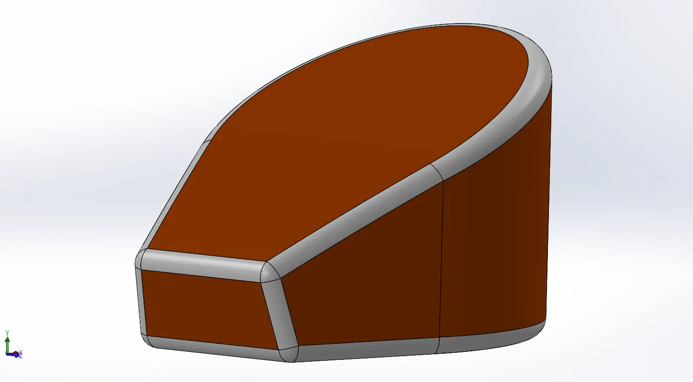
Features used
⦁ Sketch
⦁ Boss Extrude
⦁ Combine
⦁ Fillet
⦁ Shell
Combine
Combine feature combines the two or more solid bodies.
Shell
Removes material from the solid body to create thin-walled feature for the body.
⦁ Chain
The Chain is responsible for transferring the engine power to the rear wheel. The chain acts as a medium to transfer power from engine sprocket to rear wheel sprocket which in turn rotates the rear wheel.
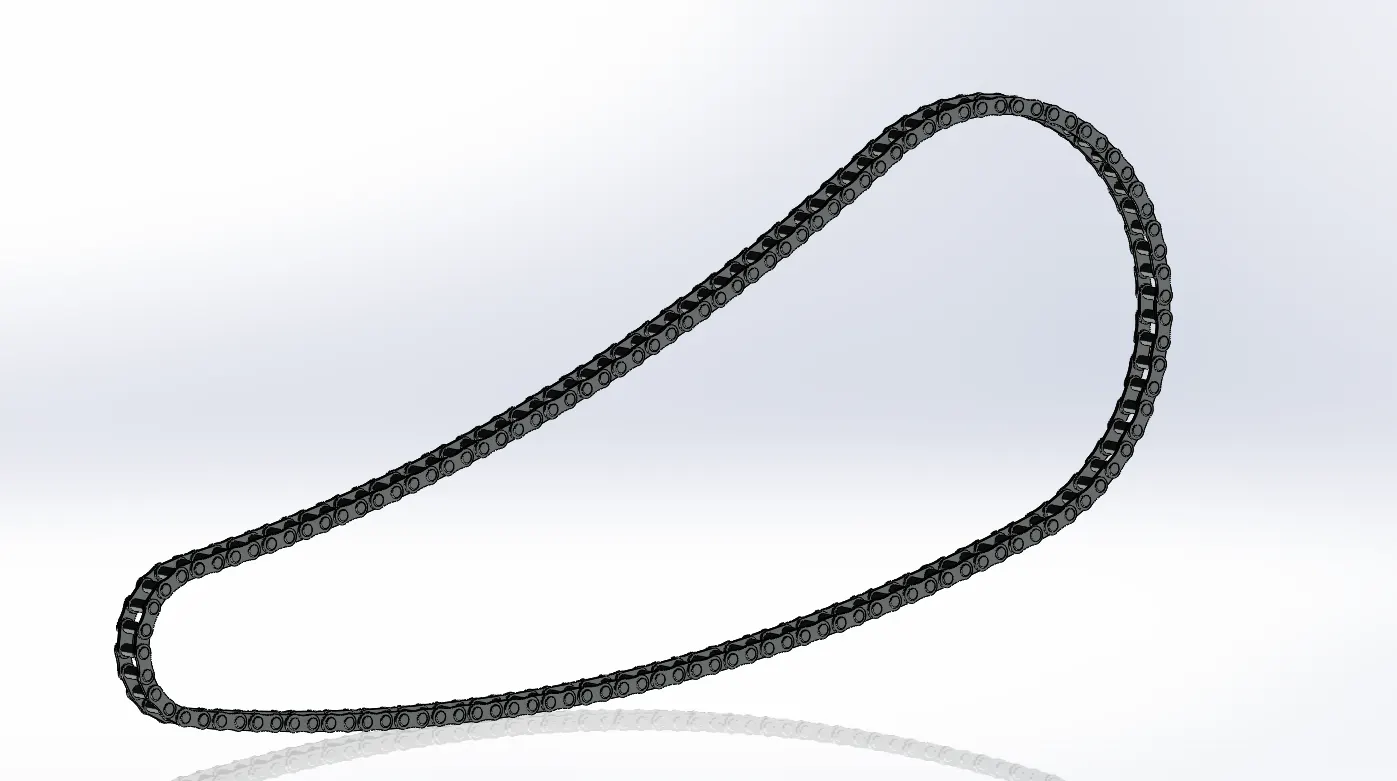
Features used
⦁ Sketch
⦁ Trim
⦁ Fillet
⦁ Blocks
⦁ Extrude
⦁ Patterns
⦁ Appearances
Blocks
Sketch Blocks within your SolidWorks sketches provide a simple, but powerful method of grouping objects together. Blocks are manipulated as one object, including constraining and dimensioning as other sketch entities. They provide a great way of dealing with imported geometry, especially when you have a lot of objects and you do not want to be concerned about constraining each entity. More than just for grouping, blocks also provide the ability to perform conceptual type design, really testing the function before committing to the form.
Patterns
The Curve Driven Pattern tool allows you to create patterns along a planar or 3D curve. To define the pattern, you can use any sketch segment, or the edge of a face (solid or surface), that lies along the plane. You can base your pattern on an open curve, or on a closed curve, such as a circle.
There are various types of patterns such as linear pattern, circular pattern, sketch driven pattern etc, which can be used according to the requirement.
⦁ Pedal
pedal is used to rest the foot on it, gives comfort for the rider. pedal is an external attachment to the chassis of the chopper.
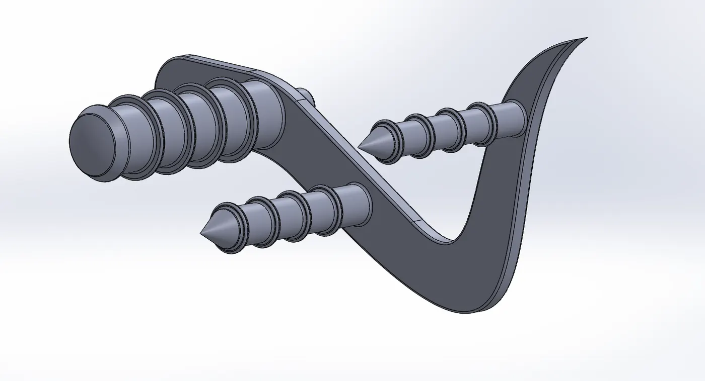
Features used
⦁ Sketch
⦁ Extrude
⦁ Fillet
⦁ Patterns (linear)
⦁ Dome
⦁ Chamfer
⦁ Appearances
Chamfer
Chamfer is useful to cut the edge or corner of a body, creates a bevel feature along an edge, a chain of tangent edges, or a vertex.
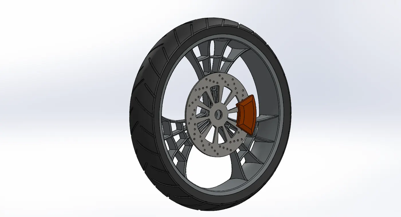
⦁ Front Wheel
Front Wheel consists of a rim which is usually made of steel or aluminium and rubber tyre is mounted in top of it. Front-wheel also consists of rotor caliper setup is fixed at the axis of rotation of the wheel.
Features used
⦁ Sketch
⦁ Revolve
⦁ Trim
⦁ Fillet Entities
⦁ Boss Extrude
⦁ Revolve cut
⦁ Pattern (Linear)
⦁ Chamfer
⦁ Fillet
⦁ Cut Extrude
⦁ Pattern (Circular)
⦁ Appearances
Linear Pattern
Patterns features, faces, and bodies in one or two linear directions. we can select reference geometry to define the pattern.we can also skip instances.
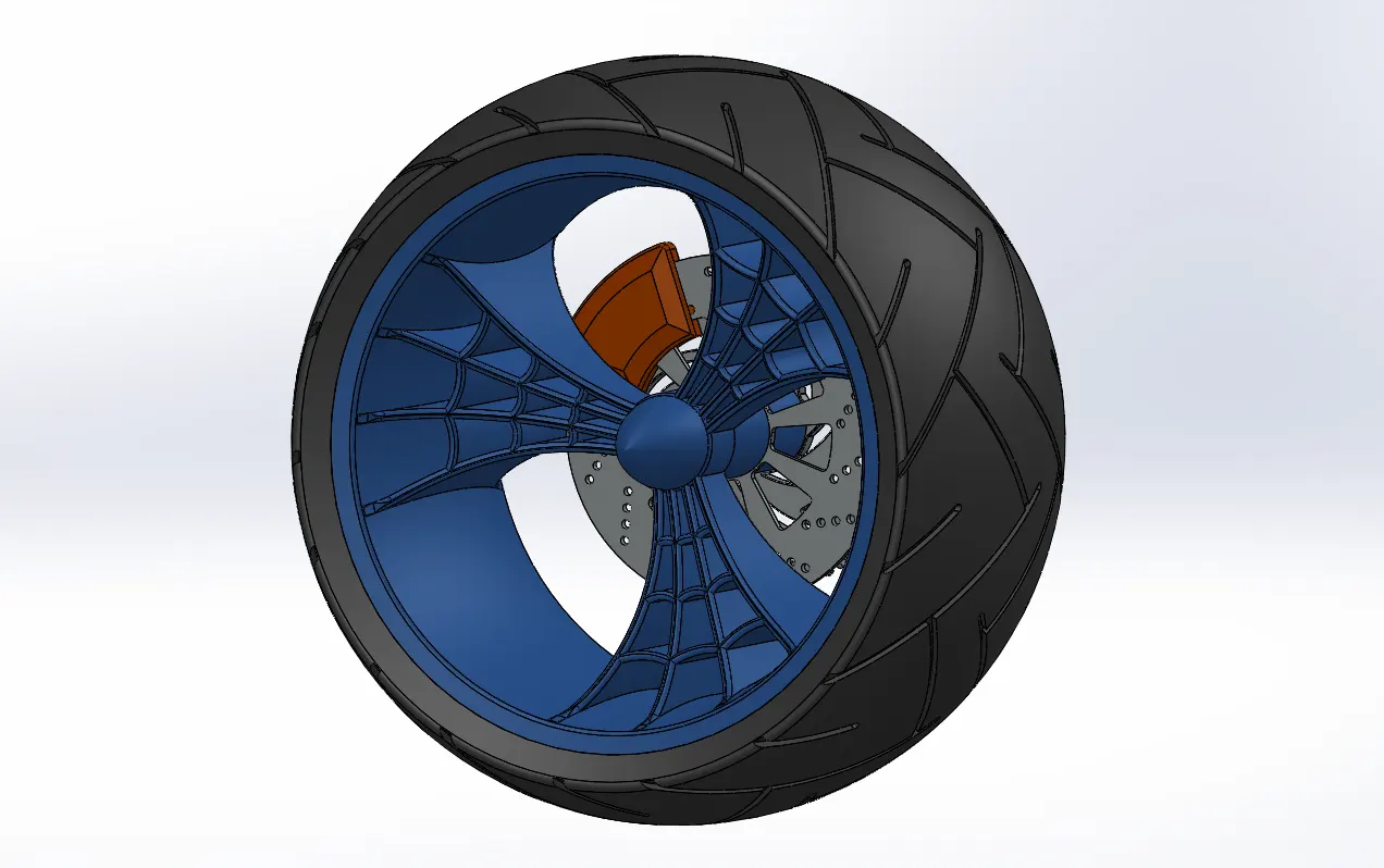
⦁ Rear Wheel
Rear Wheel additionally consists of a sprocket fixed at the axis of rotation of the wheel, Sprocket helps in the rotation of the wheel. Chain is connected to the rear wheel from engine with the help of this sprocket.
Features used
⦁ Sketch
⦁ Revolve
⦁ Trim
⦁ Fillet Entities
⦁ Boss Extrude
⦁ Revolve cut
⦁ Pattern (Linear)
⦁ Chamfer
⦁ Fillet
⦁ Cut Extrude
⦁ Pattern (Circular)
⦁ Appearances
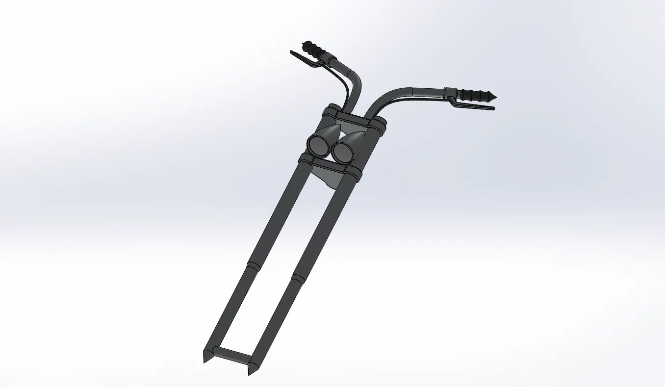
⦁ Front Fork
A motorcycle fork connects a motorcycle's front wheel and axle to its chassis. Front Fork of the vehicle mostly consists of telescopic suspension. A telescopic fork uses fork tubes which contain the suspension components (coil springs and damper) internally. This helps in the better suspension of the vehicle.
Features used
⦁ Sketch
⦁ Extrude
⦁ Trim
⦁ Revolve
⦁ Split
⦁ Plane
⦁ Convert Entities
⦁ Move/Copy Body
⦁ Dome
⦁ Mirror
⦁ Combine
⦁ Curve (Project Curve)
⦁ Sweep
⦁ Appearances
Move/Copy Body
Moves, copies, and rotate solid and surface bodies.
Mirror
Mirror feature is used to mirror the features, faces and bodies about a face or a plane or even a line.
Project Curve
Generates a 3D curve based on the selected two different sketches irrespective of there planes.
Sweep
Sweeps a closed profile along an open or closed path ( sketch or curve) to create a solid feature.
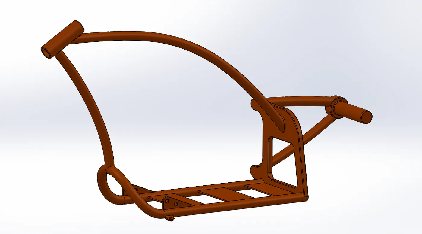
⦁ Chassis
Chassis is the skeleton of a vehicle, it is the base frame of a car, carriage, or other wheeled vehicles. All the parts of the vehicle are mounted on it. Chassis gives the firm support to the all the components of the vehicle.
Features used
⦁ Sketch
⦁ Offset
⦁ Convert Entities
⦁ Project Curve
⦁ Trim
⦁ Plane
⦁ Sweep
⦁ Split
⦁ Revolve
⦁ Cut Extrude
⦁ Fillet
⦁ Combine
⦁ Appearances
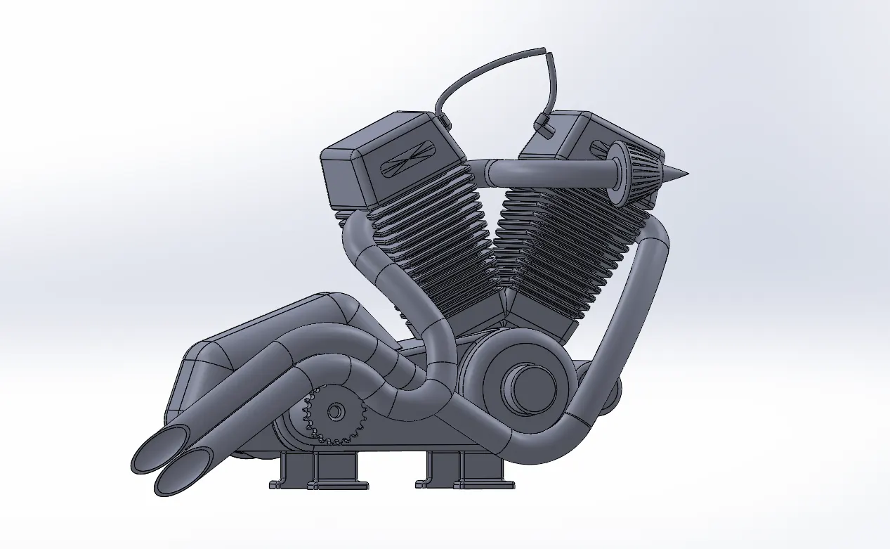
⦁ Engine
Motorcycle engines consist of pistons, a cylinder block and ahead, which contains the valve train. The pistons move up and down in the cylinder block, driven by explosions of a fuel-air mixture that has been ignited by a spark ( created by the spark plug). Valves open and close to allow the fuel-air mixture to enter the combustion chamber. As the pistons move up and down, they turn a crankshaft, which transforms the energy from the pistons into rotary motion. The rotational force of the crankshaft is transmitted, via the transmission, to the rear wheel of the motorcycle.
Features used
⦁ Sketch
⦁ Convert Entities
⦁ Trim
⦁ Revolve
⦁ Boss Extrude
⦁ Cut Extrude
⦁ Offset
⦁ Dome
⦁ Fillet
⦁ Project Curve
⦁ Composite Curve
⦁ Sweep
⦁ Mirror
⦁ Pattern (Circular)
⦁ Appearances
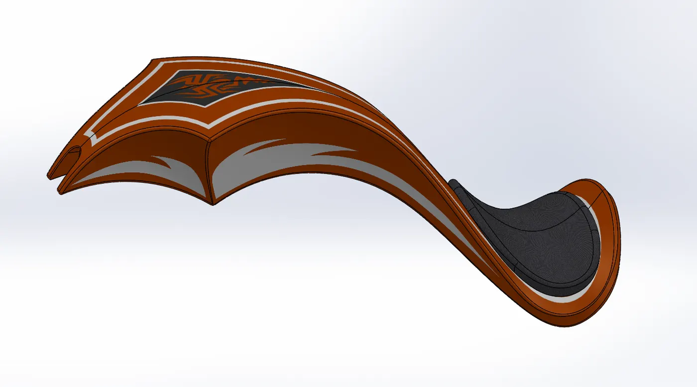
⦁ Gas Tank
Gas tank stores the fuel, which is used to run the engine. A fuel tank (also called a petrol tank or gas tank) is a safe container for flammable fluids.
Features used
⦁ Sketch
⦁ Trim
⦁ Project Curve
⦁ Convert Entities
⦁ Sweep Surface
⦁ Loft Surface
⦁ Fill Surface
⦁ Surface Trim
⦁ Surface Knit
⦁ Sweep Cut
⦁ Fillet
⦁ Appearances
Loft Surface
Loft Surfaces are surfaces generated by multiple 3D Curves or existing edges creating a smooth tangency between the selected curves. Match Points are created between each selection denoting the orientation and path of the loft surface.
Sweep Surface
Creates a surface feature by sweeping an open or closed profile along an open or closed path.
Filled Surface
Constructs a surface patch within a boundary defined by exiting model edges, sketches, or curves.
Surface Trim
Trims a surface where one surface intersects with another surface, a plane, or a sketch.
Surface Knit
This feature combines two or more adjacent, non-intersecting surfaces together.
ASSEMBLY OF THE CHOPPER
Assembly
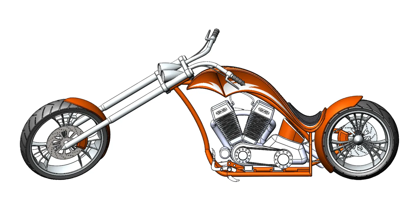
At first, the chassis part file is inserted in the assembly by using insert parts option. After insertion of the chassis part file in the assembly we need to fix chassis in the assembly environment.
Now we can insert all the chopper parts one by one by applying the mate conditions between the chassis and other parts.

Features used
⦁ Insert Part
⦁ Mates
Insert Part
We can insert the designed parts of the chopper in the assembly.
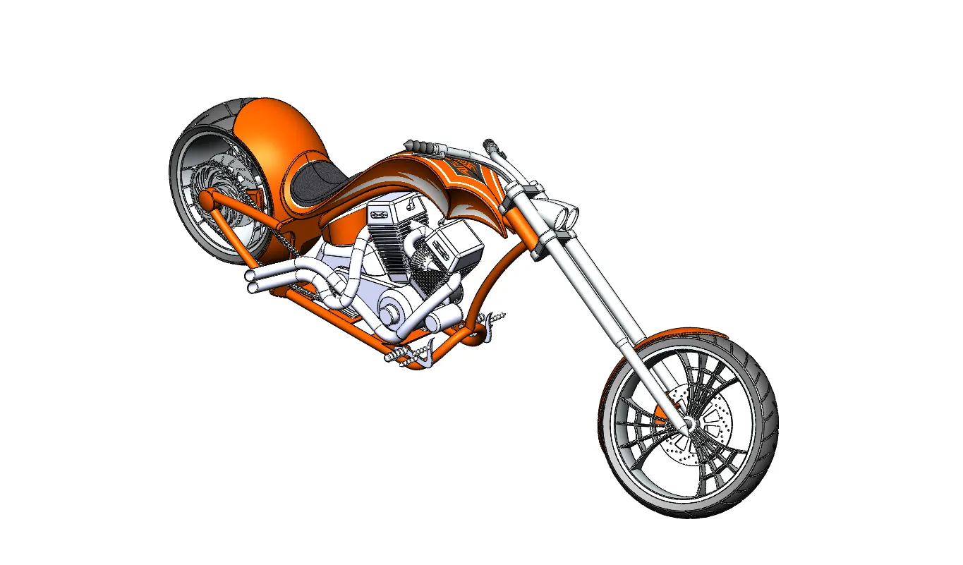
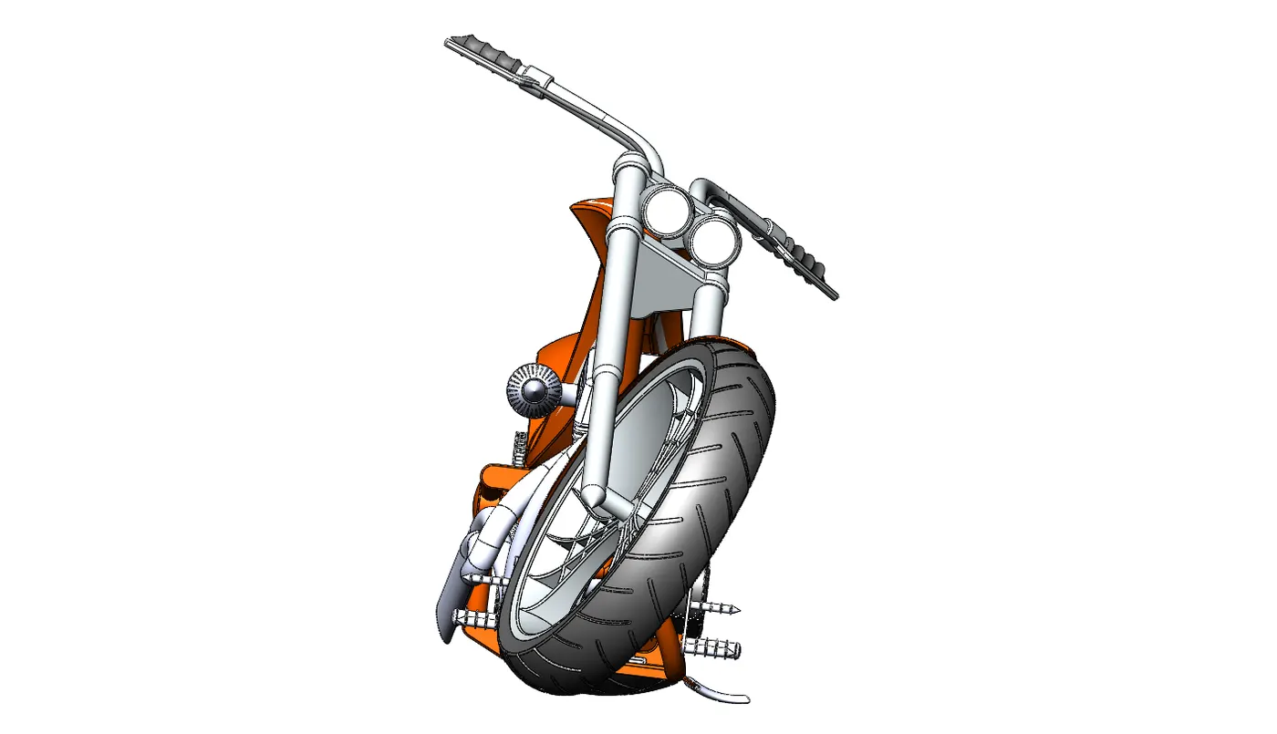
Mates
Mates create geometric relationships between assembly components. As you add mates, you define the allowable directions of linear or rotational motion of the components. You can move a component within its degrees of freedom, visualizing the assembly's behaviour.
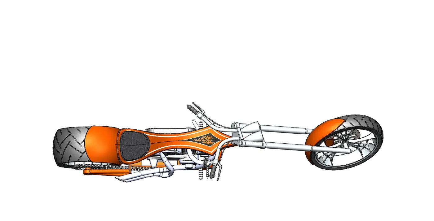
Some examples include:
A coincident mate forces two planar faces to become coplanar. The faces can move along one another, but cannot be pulled apart.
A concentric mate forces two cylindrical faces to become concentric. The faces can move along the common axis, but cannot be moved away from this axis.
Mates are solved together as a system. The order in which you add mates does not matter; all mates are solved at the same time. You can suppress mates just as you can suppress features.
RENDERING
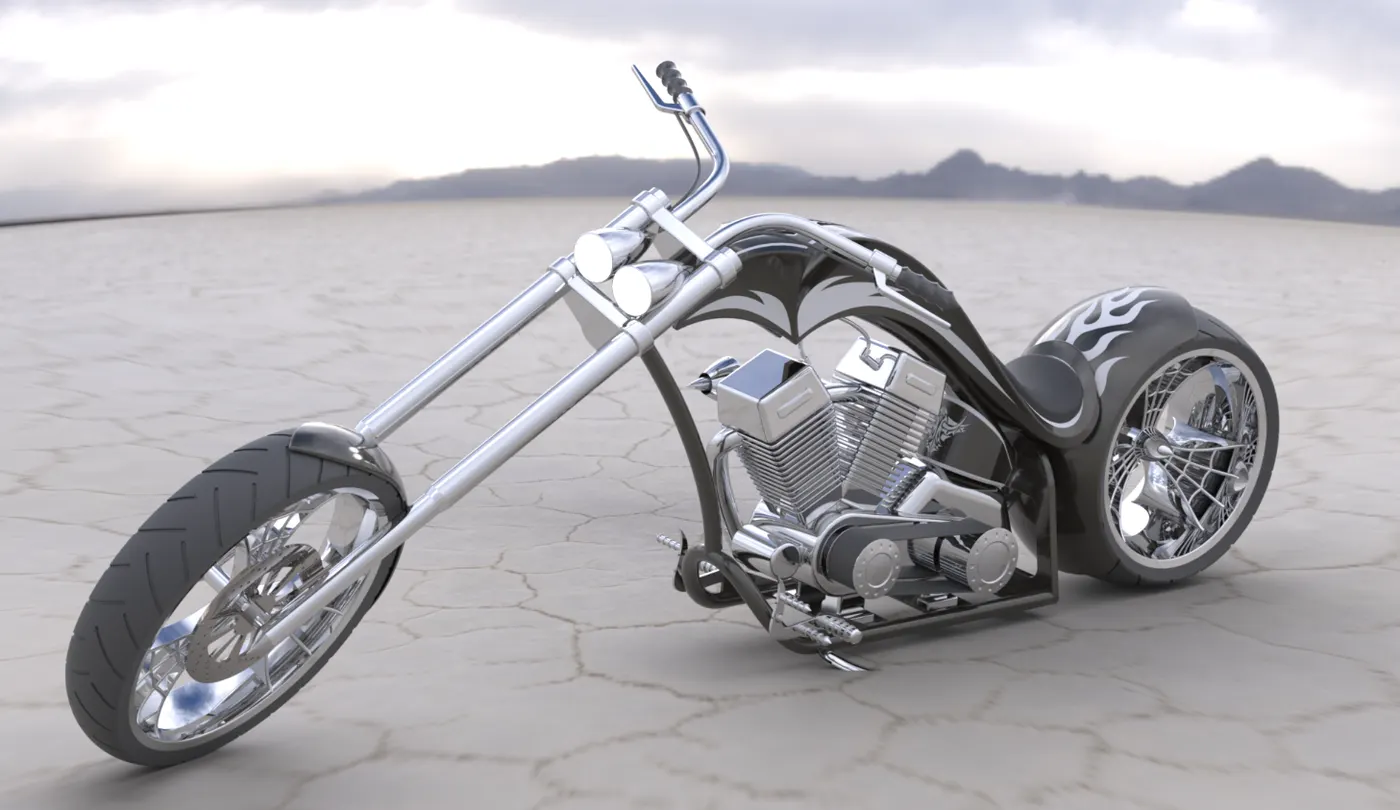
Rendering creates the photorealistic image of the designed model with a realistic environment.
Rendering can be done with the help of Photo-view 360 and Solid works Visualize.
PhotoView 360 is a SolidWorks add-in that produces photo-realistic renderings of SolidWorks models. The rendered image incorporates the appearances, lighting, scene, and decals included with the model. PhotoView 360 is available with SolidWorks Professional or SolidWorks Premium.
CONCLUSION
All the parts of the American Chopper are designed, then all of them are inserted in the assembly environment by applying mates to achieve the desired Assembly of the chopper.
The Assembly of the Chopper is rendered by using Photoview 360 and Solidworks Visualize.