Roof challenge
Introduction
Automobile roof:
The structure forming the upper covering of a building or vehicle. Hardtop convertible roofs are made of sturdy, rigid material–typically metal that's the same colour as the car body. They are occupants to the glory of the out-doors with its sunlight and fresh air. Of course, some car designers skipped right to that last part and just never bothered to put a roof on the car in the first place. provide better protection from weather and security against thieves. Detachable hardtops function as a single piece that can be removed entirely from the car and stored elsewhere.
They are various types of automobile roofs:
Convertible roofs:-
A convertible, cabriolet or spyder/spider is a passenger car that can be driven with or without a roof in place. The methods of retracting and storing the roof vary between models. A convertible allows an open-air driving experience, with the ability to provide a roof when required. Potential drawbacks of convertibles are reduced structural rigidity (requiring significant engineering and modification to counteract the effects of removing a car's roof) and cargo space.
Hardtops:-
A hardtop is a rigid form of automobile roof, which for modern cars is typically constructed from metal. A hardtop roof can be either fixed (i.e. not removable), detachable for separate storing or retractable within the vehicle itself.
Sunroof:-
A sunroof is a movable panel that opens to uncover a window in an automobile roof, allowing light and/or fresh air to enter the passenger compartment. Sunroofs can be manually operated or motor-driven, and are available in many shapes, sizes and styles. While the term sunroof is now used generically to describe any glass panel in the roof, the term "moonroof" was historically used to describe stationary glass panes rigidly mounted in the roof panel over the passenger compartment. A moonroof has a glass panel that is transparent and usually tinted. Previous terms include Sunshine Roof, Sliding Head and Sliding Roof.
T-tops:-
A T-top is an automobile roof with a removable panel on each side of a rigid bar running from the centre of one structural bar between pillars to the centre of the next structural bar. The panels of a traditional T-top are usually made of auto-grade safety glass.
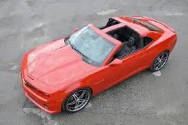
Targa tops:-
Targa top, or Targa for short, is a semi-convertible car body style with a removable roof section and a full-width roll bar behind the seats. The term was first used on the 1966 Porsche 911 Targa, The rear window is normally fixed, but on some Targa models, it is removable or foldable, making it a convertible-type vehicle. Any piece of normally fixed metal or trim that rises from one side, over the roof and down the other side is sometimes called a Targa band, Targa bar, or a wrap over the band.
Targa tops are different from T-tops, which have a solid, non-removable bar running between the top of the windscreen and the rear roll-bar, and generally have two separate roof panels above the seats that fit between the window and central t-bar.
Vinyl roofs:-
Vinyl roof refers to a vinyl covering for an automobile's top. This covering was originally designed to give the appearance of a convertible to models with a fixed roof, but eventually, it evolved into a styling statement in its own right. Vinyl roofs were most popular in the American market, and they are considered one of the period hallmarks of 1970s Detroit cars. Vinyl roofs were also popular on European- (especially UK-) and Japanese-built cars during the 1970s and tended to be applied to sporting or luxury trim versions of standard saloon (sedan) models.
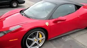
The roof is attached to the different style of the car's body by pillars A, B and C.
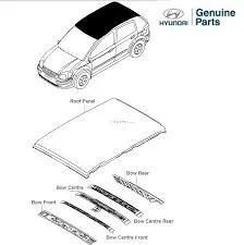
Bows:
They are added to improve the strength and fitting interior elements. Another task of roof bows is to support the interior roof liner which requires several fittings both in central and boundary areas to avoid deflections and vibrations. Some roof liners, mostly on less expensive vehicles are bonded directly to the roof panel.
Aim:
To create a Complete roof with Rails and Calculate heat distortion and snow load prediction.
Methodology:
Creating Roof outer panel.
Creating Bows.
Creating Reinforcement Rail.
Creating Roof Reinforcements.
Creating Sunroof.
Thickening Roof outer, bows and rails.
Procedure:
Initially, Extract the parent surface in a working geometrical set.
Roof:
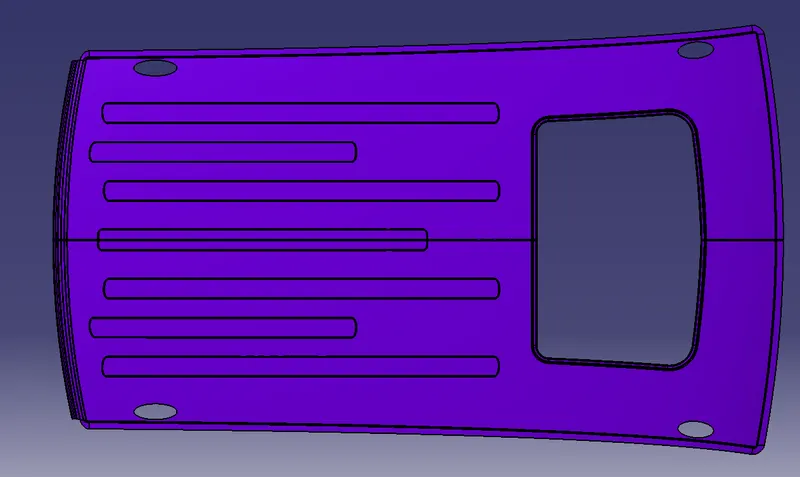
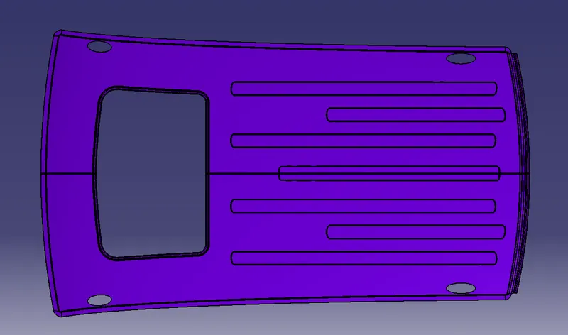
Offset the outer skin from the parent file at 0mm.
Now, extract the edges of the roof on three sides. Sweep it 3deg with draft direction with 15mm length.
After that sweep, the recent sweep edges parallel to the roof surface to 20mm length.
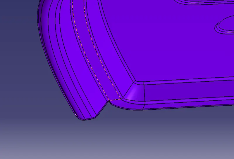
Create points on the corner on the roof by giving support to the roof edge and create a spline by giving support.
Split the portion and create a multi-section to join the sweep surfaces at the corner.
Join all the operations and give fillets to it.
Create another sweep on the rear end of the roof with 25mm length, 35deg draft direction, again sweep with 15mm length at 0deg draft direction and again sweep with 84deg draft direction and 10mm length.
Bow:
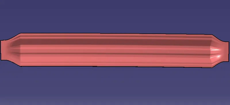
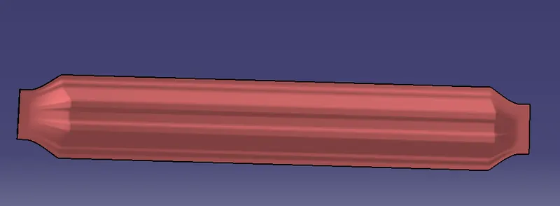
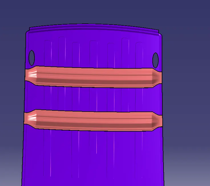
Create points from the edges of the styling edges and create a midpoint project it on the other side and create a straight line.
Now offset the roof down with offset of 5, 10, 30 and 35.
Create parallel curves with a maximum distance of 75-80mm.
Then simultaneously decrease the value and split it with the offset surfaces.
The use blend option to connect and give fillets.
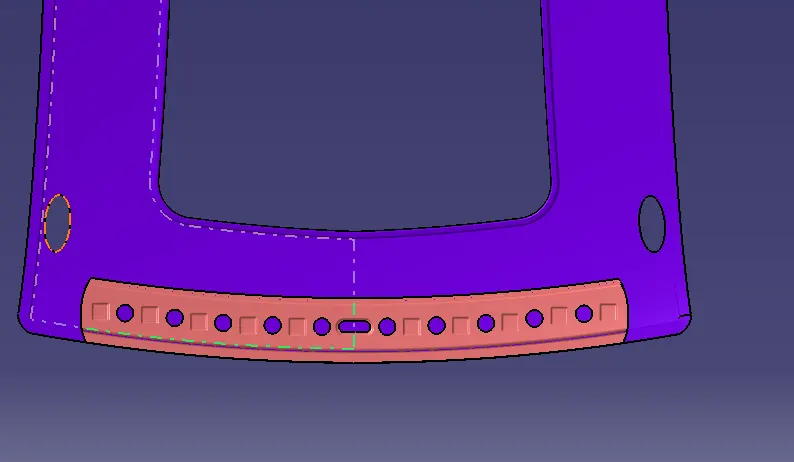
Front roof Rail:
Offset the surface 32mm below and split it using a parallel curve with an 80mm distance.
Create an offset at 28mm and 25mm and spilt it using parallel curves and blend them.
Similarly, sweep the front edge 52deg draft direction and trim it with the ditch area offsetted surface and give filets to it.
After fillets are given embossments in the lower area towards the roof panel.
Rear roof Rail:
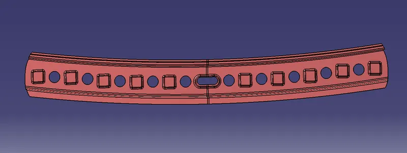
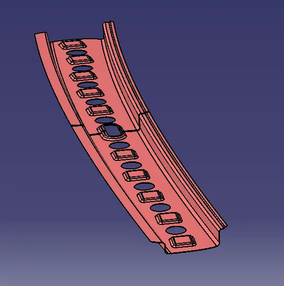
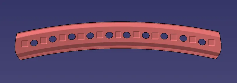
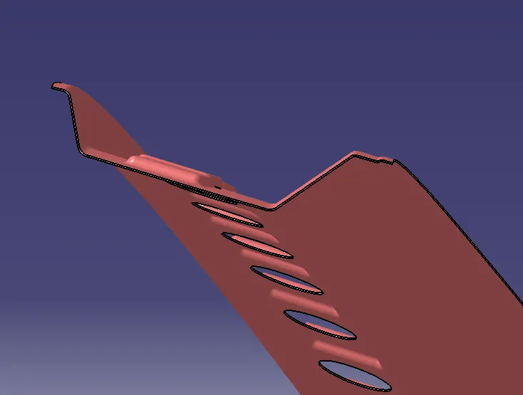
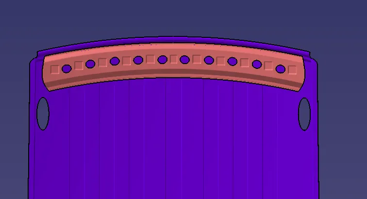
Offset the surface 40-50mm below and split it using a parallel curve with a 120mm distance.
Create an offset at 35mm and 33mm and spilt it using parallel curves and blend them.
Similarly, sweep the front edge 32deg draft direction and trim it with the offsetted surface and give filets to it.
After fillets are given embossments in the lower area towards the roof panel.
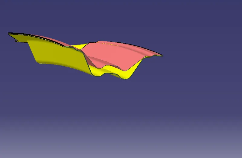
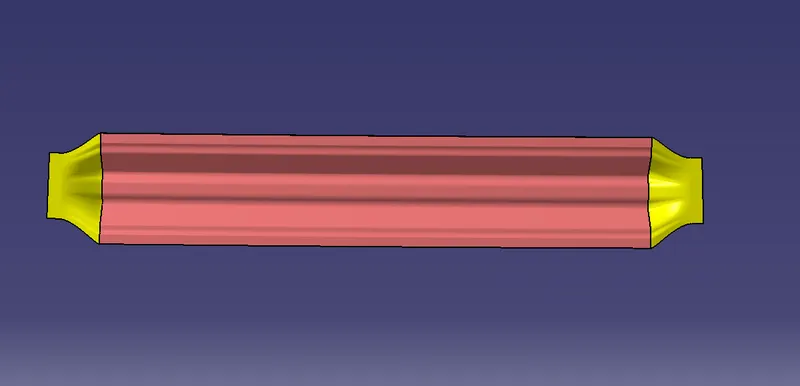
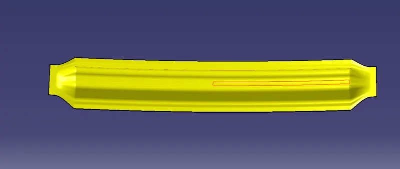
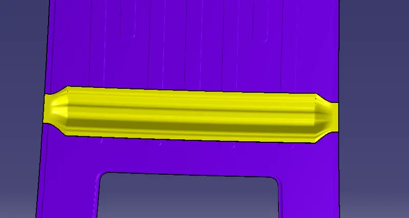
Centre Reinforcement:
Create points from the edges of the styling edges and create a midpoint project it on the other side and create a straight line.
Now offset the roof down with offset of 5, 10, 35 and 3540.
Create parallel curves with a maximum distance of 90-95mm.
Then simultaneously decrease the value and split it with the offset surfaces.
The use blend option to connect and give fillets.
Thickening Parts:
As per the standards, the thickness is assigned
For Roof Outer Panel - 0.75
For Bows - 0.65
For Front and rear Rail - 0.65
For Reinforcement - 1.5
HEAT DISTORTION FORMULA
W = [1.73 x 10^(-3) x L] + [1.85 x 10^(-8) x (R^2)/t] + [ 1.10x10^(-3) x l] - 2.68
Judgement Condition : OK< 2.7> 3.1
Where
L = Roof Length in X-Direction[mm](Roof dimension in 0-Y)
R = Roof curvature
R = 2(Rx*Ry)/(Rx+Ry)
Rx = X curvature
Ry = Y curvature
t = Roof plate thickness [mm]
l = Bow Roof Span [mm]
HEAT DISTORTION CRITERIA
|
S.NO |
BOW's | Rx | Ry | R | I | L | t | R^2/t | W | OK/NG |
| 1 | CNTR-BOW 1 | 4235.796 | 9308.554 | 5822.226 | 260.654 | 2031.117 | 0.75 | 45197754.13 | 1.955 | OK |
| 2 | BOW1-BOW2 | 3689.629 | 12101.731 | 5655.104 | 184.498 | 2031.117 | 0.75 | 42640268.33 | 1.823 | OK |
| 3 | BOW2-RR | 3221.937 | 14968.534 | 5302.52 | 275.115 | 2031.117 | 0.75 | 37488957.8 | 1.828 | OK |
Where,
CNTR- Centre Rail
RR- Rear Roof Rail
Note:- All the dimensions are in mm.
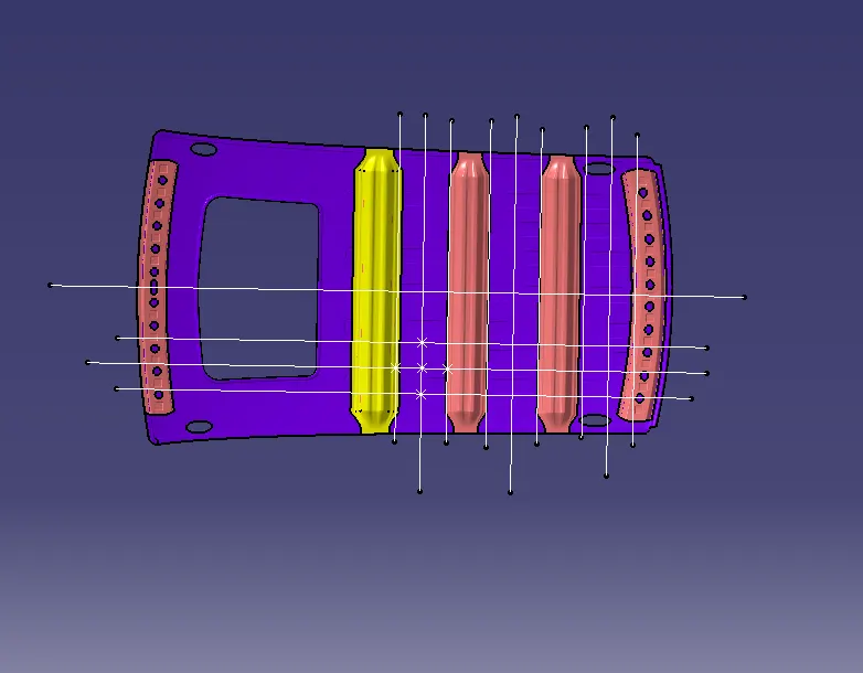
SNOW LOADED FORMULA
Qr = [Iy x t2] / [α x s x [(Rx + Ry)/2]2 x 10-8]
Note: The Qr value given over here is correct. There was a typo error in the formula given in the video.
Where
α = My x Lx2 x 10-12 , My = Y(Ly-Y)
Judgement condition = Qr ≥ 3.1
250 ≤ s ≤ 380
t = Roof plate thickness [mm]
Ly = Distance between the front and rear roof Rails on the Vehicle along with 0Y[mm]
Length of Roof panel with the centre point between Roof rail Front /Rear as the reference point of the front and the rear.
Lx = Distance between the Left and Right end of the roof on the Roof BOW [mm]
Width of the roof panel exposed on the surface.
Y = Distance front Front Roof Rail to Roof BOW[mm]
s = Distance for which Roof BOW bears divided load [mm]
s = L1/2 + L2/2
Iy = Geometrical moment of inertia of Roof BOW (Y cross-section )[mm4]
Rx = Lateral direction curvature radius of roof panel Y cross-section on Roof BOW [mm]
Roof panel curvature Radius of the Length Lx in Front view
Ry = Longitudinal Direction curvature radius of the Roof panel X cross-section on Roof BOW [mm]
Roof panel X curvature radius of length s in Side view
SNOW LOADED CRITERIA
| S.no | BOW's | Rx | Ry | t | s | α | Lx | Ly | Iy | y | Q | Determination(Qr) |
| 1 | CNTR-BOW 1 | 4024.436 | 9028.046 | 0.75 | 360.501 | 0.149 | 1079.607 | 2033.703 | 1231 | 361.131 | 25.331 | OK |
| 2 | BOW1-BOW2 | 4304.837 | 13058.366 | 0.75 | 356.591 | 0.82 | 1061.546 | 2033.703 | 4024 | 359.872 | 29.624 | OK |
| 3 | BOW2-RR | 3660.2 | 17923.489 | 0.75 | -nil- | -nil- | 1049.807 | 2033.703 | 4024 | 353.31 | -nil- | -nil- |
Where,
CNTR- Centre Rail
RR- Rear Roof Rail
Note:- All the dimensions are in mm.
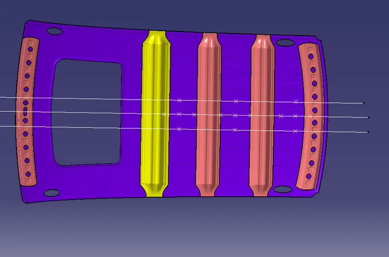
SECTION MODULUS
Section modulus = Moment of Inertia/distance between the neutral axis and the end of the object.
`S`=`I``/``y`.
ROOF OUTER
I = `613700 mm^4`
y = `2033.703 mm`
S =`613700 /2033.703`
= `301.764 mm^3`
FRONT RAIL
For the front roof rail
I = `9.364x10^3 mm^4`
y = `63.889mm^4`
S = `9.364x10^3/63.08`
= `148.44mm^3`
CENTRE RAIL
For Centre rail
I = `6152mm^4`
y = `53.794 mm`
S = `6152/53.794`
= `114.362 mm^3`
CENTRE REINFORCEMENT
For centre reinforcement
I = `10470mm^4`
y = `46.004 mm`
S = `10470/46.004`
= `227.5889 mm^3`
BOW 1
For BOW 1
I = 4352mm^4
y = 46.012
S = 4352x46.012
= 94.573 mm^3
BOW 2
For BOW 2
I = `6176 mm^4`
y = `53.997 mm`
S = `6179/53.997`
= `114.375 mm^3`
REAR RAIL
For the rear roof rail
I = `58070 mm^4`
y = `86.867 mm`
S = 58070/86.867
= `668.493 mm^3`
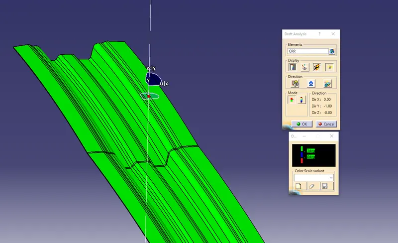
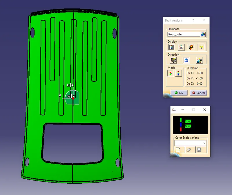
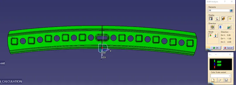
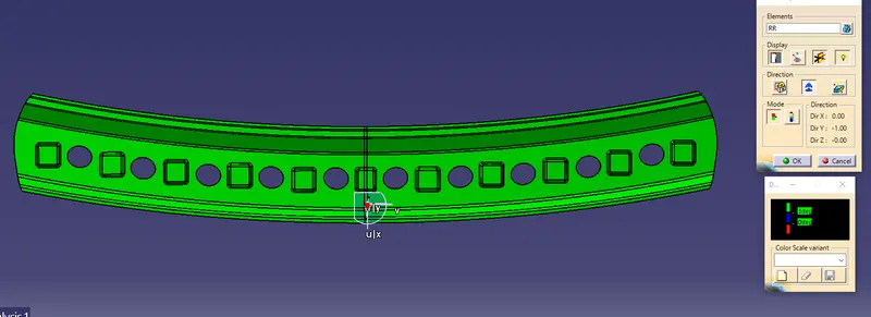
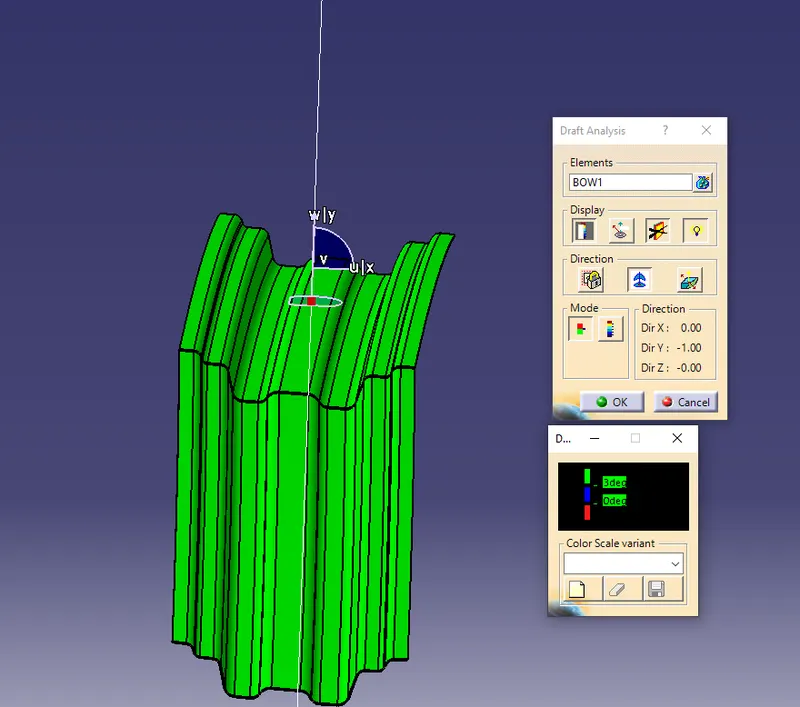
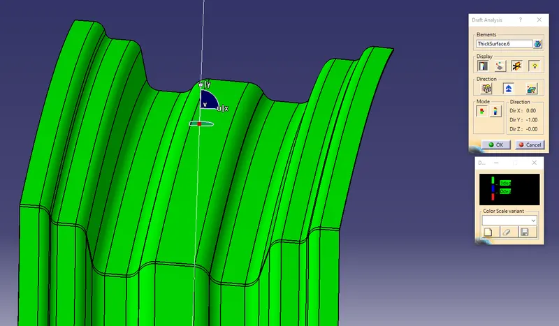
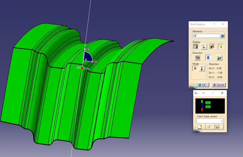
DRAFT ANALYSIS:
Roof:
Front Rail:
Rear Rail:
BOW1:
BOW2:
Centre Rail:
Centre Reinforcement: