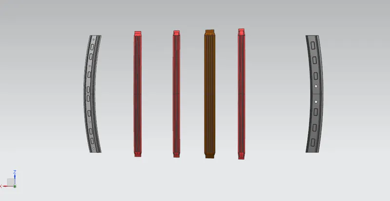
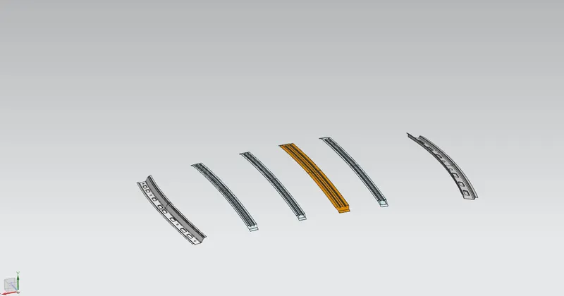
Roof challenge
DESIGN OF ROOF AND CURVATURE ANALYSIS
Objective:
To design the Automotive Roof based on the given styling surface and to analyze the prepared model to check the manufacturability and the feasibility of the design.
Introduction:-
The Roof of a car is the component which encloses the passenger compartment from the top. It protects the Passengers and the interior of the car from external environments thus providing a safe and isolated cabin. The roof plays an important role in the safety, especially in the case of roll-over accidents. To achieve better safety results the roof is designed with reinforcement structures such as rails. All these components are designed to satisfy the basic functions of the roof
First thing to consider while designing the roof is the opening angle, of the flanges such that there is no negative draft.If the roof rail is flat it is weak and if it is tilted or curved then it has more strength.As the roof is large so to increase the strength of the roof where it appears flat due to its long distance Roof Bow are given to increase the strength of the roof.Since the roof has numerous functions so the roof has to be stronger enough to withstand the damage experienced by it. To have good strength and stiffness, the Roof consists of components
The safety requirements and to improve the performance of the vehicle by weight optimization.
The major components of the Roof are
- Outer panel/ Shell
- Front roof rail
- Rear roof rail
- Bow roofs
- Central roof rail
Functional requirements:
- Headroom clearance: 80 mm minimum
- Front visibility criteria
- Enough flange length to support the windshield glass & its components
- 2 mm clearance at the flange edge for trims
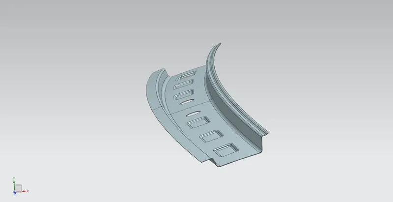
1.Front roof rail
The front rail supports the roof outer shell at the front end. It is mounted with brace roof rail reinforcement on both ends. The rails are provided with embosses to improve the strength and the rail is connected to the outer panel using mastic sealants on one side and the other joinery is spot welded.Embosses are given to improve the strength. They have created considering the manufacturing requirements
The section is created by considering the front visibility criteria and minimum headroom clearance of 80mm. A flange of 15 mm is provided to support the windshield glass & its components,
Geometric requirements:
- Thickness – 0.75 to 1.5 mm
Manufacturing requirements:
- Small emboss depth should be less than 6 mm
- Mounting and welding areas should be flat
- Minimum fillet radius should be 3mm+thickness
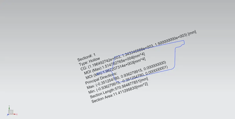
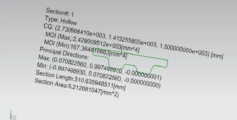
Section Modulus Analysis of Front section:
2.Outer Panel / Shell
The outer panel is the A-class surface of the roof which encloses the top of the passenger compartment. It is designed to match the input styling surface, thus getting better aerodynamic performance as intended. It also has a significant role in the aesthetics of the vehicle. The outer panel is mounted to the roof rails with the help of mastics and the ditch areas are mounted with spot welds. The commonly used materials for the outer panel are Steel and Aluminum alloys.
Developing the ditch area
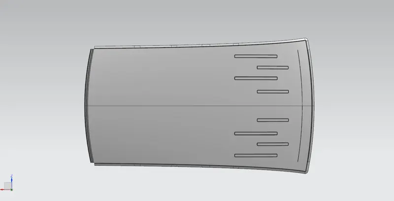
Flanges are created on four sides of the roof as per the above-mentioned requirements. The front end flange is given with a width of 21.50 mm to provide adequate space for the rubber sealing, mounting of windshield glass, etc. The rear ditch area is created to allocate the hinges of the backdoor and to allow the swinging of the backdoor to the required opening angle. Some embosses are also provided on the rear to increase the strength locally
Geometric requirements:
- Thickness: 0.75 mm
- Ditch area-minimum flange width: 15 mm
Manufacturing requirements:
- Small emboss depth should be less than 6 mm
- Mounting and welding areas should be flat
- Minimum fillet radius should be 3mm+thickness
- Tool opening angle is 3 degrees
3.Center roof rail
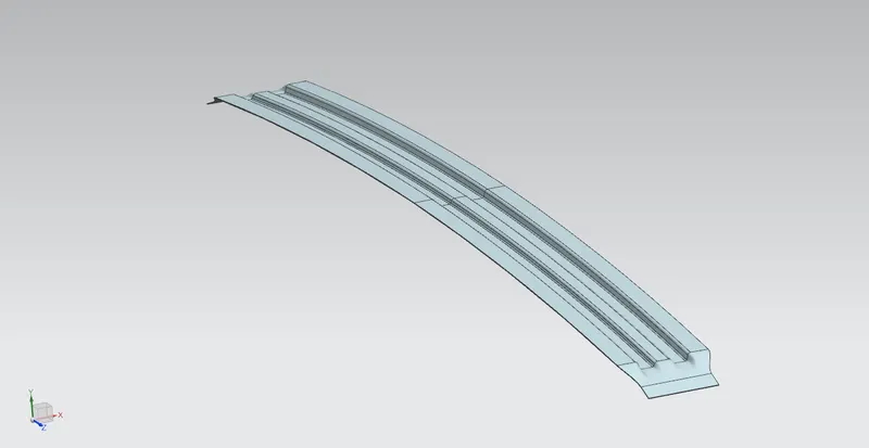
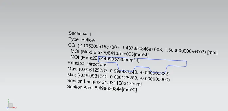
The reinforcement roof at the center is the supporting member at the middle which is mounted to the B pillars on either side. They are attached to the outer panel using mastic sealants. Sometimes it acts as bow roof and sometimes bow roofs are also provided with the reinforcement roof center. In some vehicles a room lamp mounting provision is also given on this part.
Design Considerations:
Geometric requirements:
- Thickness: 0.75
Manufacturing requirements:
- Small emboss depth should be less than 6 mm
- Mounting and welding areas should be flat
- Minimum fillet radius should be 3mm+thickness
Section Modulus Analysis
4. BOW roofs
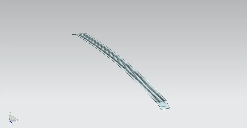
The Bow roofs are given to improve the torsional stiffness and load-bearing capacity of the roof structure. The number of bow roofs provided will depend upon the overall dimensions of the roof. They are attached to the outer panel using mastic sealants. Each mastic point will have up to 80 mm circular effective area. The positioning of bow roofs is done based on curvature study. The heat distortion criteria and snow load criteria are checked to analyze the position of the bows in various conditions
1: Creating the swept surface that meets the design requirements with the outer surface geometry as reference
Geometric requirements:
- Thickness – 0.75-1.25 mm minimum
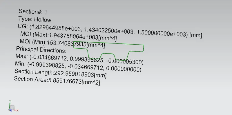
BOW ROOF 1
Section Modulus Analysis
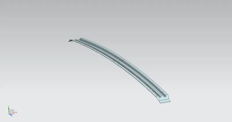
BOW ROOF 2
Section Modulus Analysis
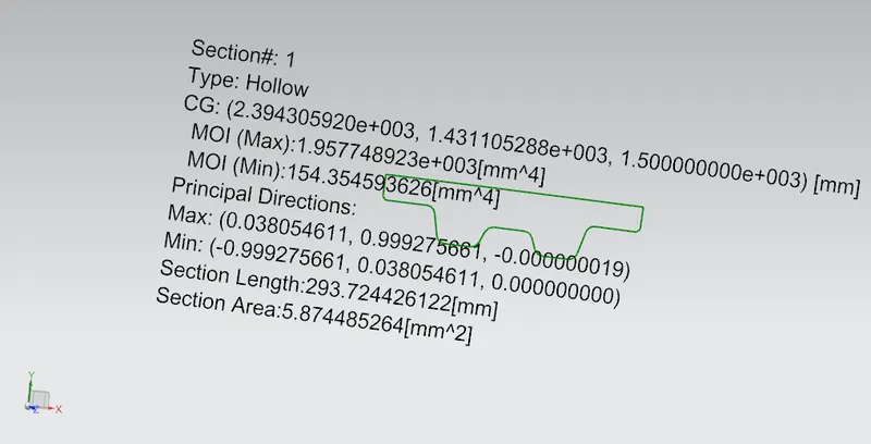
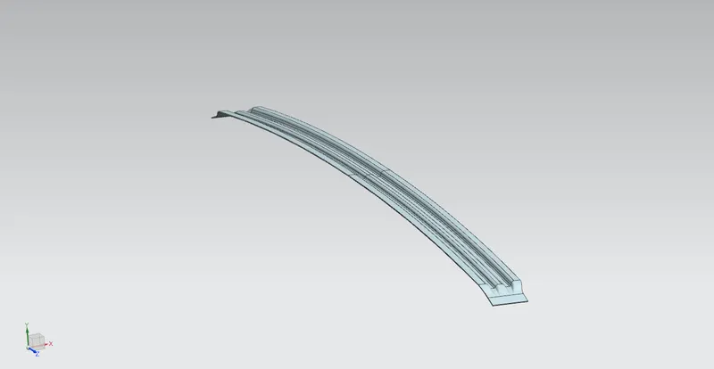
BOW ROOF 3
Section Modulus Analysis
The mastic sealant holds the bows and outer panel together. Each point will have an effective circular area of 80 mm in diameter. The mastic sealant helps to improve the elasticity of the outer panel. They also improve the NVH characteristics of the roof.
5.Rear Roof Rail
The rear roof rail is similar to the front rail. It is designed to support the back end of the roof and the hinge of the backdoor is also mounted on it
Functional requirements:
- Rear headroom clearance: 80mm minimum
- Space for mounting the backdoor hinge
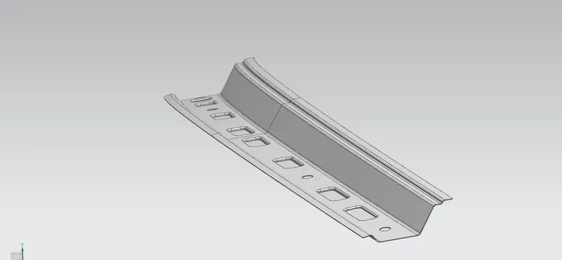
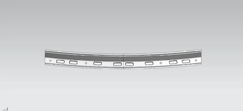
Curvature Study
To satisfy heat distortion and snow load performance of the roof, we have to determine the desired optimum location of bow roofs and roof plate thickness. If the roof is exposed to high temperatures for a long time the roof structure will tend to deform. This study will help to check whether our design is valid and if not will help to determine the optimum position of the rails to avoid the deformation of the roof. Similarly if the roof is subjected to the heavy load of snow, it will tend to deform or fail. To improve the strength under the snowed condition we have to position the rails at desired specific locations
Heat distortion criteria:
W = [1.73x10^-3 x L]+[1.85x10^-8 x (R^2)/t] +[ 1.10x10^-3 x l]-2.68
Judgment Condition: OK<2.7mm L = Roof Length in X-Direction[mm](Roof dimension in 0-Y) R = Roof curvature R = 2(Rx*Ry)/(Rx+Ry) Rx = X curvature Ry = Y curvature t = Roof plate thickness [mm] l = Bow Roof Span [mm] ROOF L Rx Ry R t l W CONDITION FR & B1 2032 5785.5 3322.83 4221.13 0.75 600 1.935 Ok B1 TO MID 2032 4902.31 6749 5679.30 0.75 185 1.83 OK MID TO B2 2032 4297.81 9269 5872.62 0.75 213 1.91 OK B2 TO B3 2032 3762.23 12007 5729.27 0.75 325 2.00 OK B3 TO REAR 2032 3267.95 15195 5377.44 0.75 323 1.90 OK Qr = [Iy x t2] / [α x s x [(Rx + Ry)/2]2 x 10-8] Where α = My x Lx2 x 10-12 My = Y(Ly-Y) Where t = Roof plate thickness [mm] Ly = Distance between the front and rear roof Rails on the Vehicle along with 0Y[mm] Length of Roof panel with the center point between Roof rail Front /Rear as the reference point of the front and the rear. Lx = Distance between the Left and Right end of the roof on the Roof BOW [mm] Width of the roof panel exposed on the surface. Y = Distance front Front Roof Rail to Roof BOW[mm] s = Distance for which Roof BOW bears divided load [mm] s = L1/2 + L2/2 Iy = Geometrical moment of inertia of Roof BOW (Y cross-section )[mm4] Rx = Lateral direction curvature radius of roof panel Y cross-section on Roof BOW [mm] Roof panel curvature Radius of the Length Lx in Front view Ry = Longitudinal Direction curvature radius of the Roof panel X cross-section on Roof BOW [mm] Roof panel X curvature radius of length s in Side view Judgement condition = Qr ≥ 3.1 250 ≤ s ≤ 380. Here we got the Qr values greater than 3.1 but as you can see the s value for the last two is greater than 380mm hence we introduce beads on the roof panel. The longer beads cover the rear portion of the roof to provide more strength. S. no. Bow I(y) α Lx Ly Y s Rx Ry t Qr Determination 1 FR to BW1 974.19 1.08 1136.25 1942 600 450 3908.18 4038.79 0.75 7.12 OK 2 BW1 to CTR 882.1 0.572 1117.83 1942 275 282 3792.12 6674 0.75 11.22 OK 3 CTR to BR2 981.99 0.582 1104.46 1942 341 315 4114 9450.14 0.75 6.55 OK 4 BR2 to BR3 1013.45 0.667 1093.4 1942 430 378.5 4349 12698.4 0.75 3.7 OK 5 BR3 to RR 1942 3944.4 16820.7 0.75 FINAL ROOF DESIGN Result: The Roof assembly is designed based on the given styling surface, considering all the geometric, manufacturing, and functional requirements. Drive link:- Roof design part file https://drive.google.com/file/d/1V7RspxnxKSv-m7W859ln4LCxC0qeKmxt/view?usp=sharing
(mm^4)