Assembly of Yacht
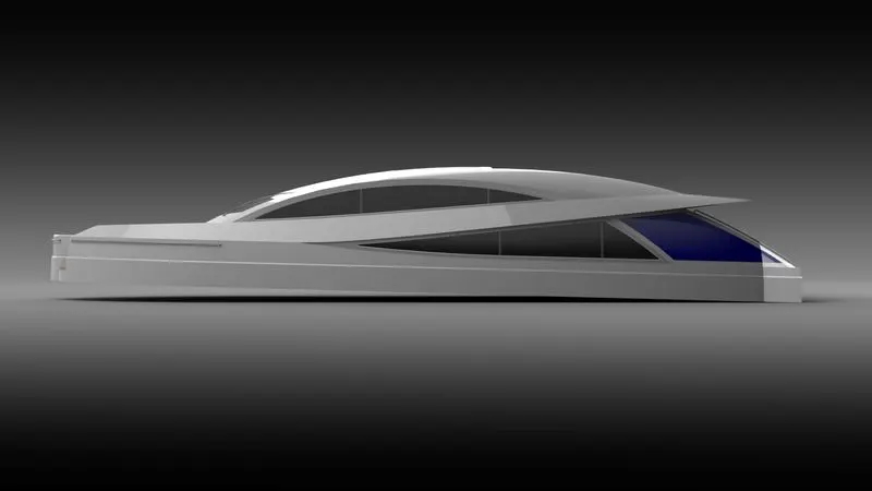
MODELING, ASSEMBLY, PHOTOREALISTIC RENDER OF AN SUN SEEKER PREDATOR YACHT
OBJECTIVE
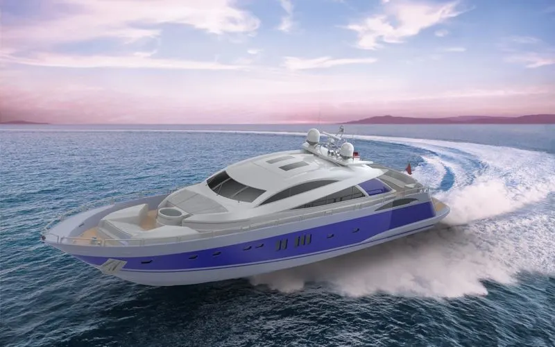
Main objective of this project is to Create a photo-realistic Conceptual model of an sunseeker predator yacht using solid works.By creating part drawings, converting them to 3D models, assembling the created parts and finally giving it a photorealistic view by rendering the model using Photoview-360.
INTRODUCTION
SOLIDWORKS
Solid works is a 3D-Modelling Computer Aided Design (CAD) and Simulation based software. To create a 3D Model, it uses the parametric future based approach (Developed by PTC) by taking the inputs from the user
YACHT
A yacht is watercraft used for pleasure or sports. The term originates from the Dutch word jacht (which means "hunt"), and originally referenced light, fast sailing vessels that the Dutch Republic navy used to pursue pirates and other transgressors around and into the shallow waters of the Low Countries.
Today's yachts are almost exclusively for leisure. A yacht is any sail or power vessel used for pleasure, cruising, or racing. The word often connotes luxury; however, luxury is not a quality necessary to meet the definition; nor is it always desirable. Many racing yachts are stripped-out vessels with a minimum of accommodations to lower weight.
DESIGN METHODOLOGY
Idea is the primary requirement to design/model any product.
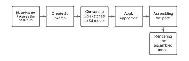
In this project the blueprints are taken as the base files for the construction of the yacht Model. Blueprints are arranged and saved as the blueprint setup for the base of the modeling
MODELLING
The Predator yacht consists of
- Hull
- Front seat
- Middle seat
- Rear seat
- Superstructure
- Garage door
- Propeller
- Radar
- Radarmast
The major Tools/Features used in the solid works for modeling the chopper were
1.Creating a 2D sketch:A 2D sketch is the base to create a 3D model. It is usually created on the X-axis & Y-axis. This includes lines, circles, rectangles, splines, etc.
- The Status of a Sketch
The current status of a sketch is displayed in the lower right corner of the screen.
Fully Defined = Black
Under Defined = Blue
Over Defined = Red
2.Geometric relation: Geometric relations are one of the most powerful features in SOLIDWORKS.They’re used in the sketch level to control the behaviors of the sketch entities when
they are moved or rotated and to keep the associations between one another
3.Project curve:
- Click Project Curve on the Curves toolbar, or Insert > Curve > Projected.
- In the PropertyManager, under Selections, set Projection type to one of the following:
- Sketch on faces
- Use this selection to project a sketched curve onto a model face.
- Under Sketch to Project , select the curve in the graphics area or from the flyout FeatureManager design tree.
- Under Direction of Projection, select a plane, edge, sketch, or face as the direction of the projected curve.
- Under Projection Faces , select the cylindrical face on the model where you want to project the sketch.
- Select the Reverse projection check box, or click the handle in the graphics area, if required.
- Select Bi-directional to create a projection that extends on both sides of the sketch
4.lofted surface:
- Create a plane for each profile section of the loft.
- Sketch the section profiles on the planes. You can create all section and guide curve sketches inside a single 3D sketch.
- If necessary, create guide curves.
- Click Lofted Surface (Surfaces toolbar) or Insert > Surface > Loft.
- Set the PropertyManager options.
- Click OK .
5.Extrude surface : You can create extruded surfaces from models that include 2D or 3D faces and knit the extruded surfaces to surrounding features.
- Click Insert > Surface > Extrude.
- Select a face:
- To extrude from a 3D face, select a 3D face.
- To extrude from a 2D face, press Alt + select the planar face.
You can select either a surface or the face of a solid body.
You can also preselect the 3D faces to extrude before clicking Insert > Surface > Extrude.
- Select other faces to define the extrude as required.
You can select faces that are not touching when you create a surface extrude in a given direction.
- Select the end condition.
- For 3D faces, select a plane, edge, 2D face, or sketch line to define the direction of extrusion .
6.Revolved surface: To create a revolved surface:
- Sketch a profile and a centerline around which to revolve the profile.
- Click Revolved Surface (Surfaces toolbar) or Insert > Surface > Revolve.
- Set the PropertyManager options.
- Click OK .
7.Swept surface: To create a swept surface:
- Create planes for sketching the sweep profile, sweep path, and if necessary, the guide curves.
- Sketch the sweep profile and path on the planes that you created.
You can also sketch the sweep path on a model face or use a model edge for the path.
- If you are using guide curves, create coincident or pierce relations between the guide curves and the profile.
- Click Swept Surface (Surfaces toolbar) or Insert > Surface > Sweep.
- Set the PropertyManager options.
- Click OK .
8.offset surfaces: To create offset surfaces:
- Click Offset Surface (Surfaces toolbar) or Insert > Surface > Offset.
- In the PropertyManager:
- Select surfaces or faces in the graphics area for Surface or Faces to Offset .
- Set a value for Offset Distance.
You can create an offset surface with a distance of zero.
- If necessary, select Flip Offset Direction to change the direction of the offset.
- Click OK
9.Filled Surface: The Filled Surface feature constructs a surface patch with any number of sides, within a boundary defined by existing model edges, sketches, or curves, including composite curves.
- Correct a part that does not import correctly into SOLIDWORKS (where there are missing faces).
- Fill the holes in a part used for core and cavity molding.
- Construct a surface for industrial design applications.
- Create a solid. Include features as separate entities, or merge those features.
To create a filled surface, click Filled Surface on the Surfaces toolbar, or click Insert > Surface > Fill, set the PropertyManager options, and click OK .
10.Trim surface:You can use a surface, plane, or sketch as a trim tool to trim intersecting surfaces. You can also use a surface in conjunction with additional surfaces, as mutual trim tools. Trim surface includes the following options:
To trim a surface:
- Create two or more surfaces that intersect at one or more points, or create a surface that intersects with a plane or has a sketch on its face.
- Click Trim Surface on the Surfaces toolbar, or click Insert > Surface > Trim.11.Delete face: You can delete faces from surface and solid bodies.The Choose Option dialog box appears when you select several entities on a model and press Delete. The dialog box is dynamic, with the appropriate selections available depending on what entities you select on the model.
12.Ruled surface: The Ruled Surface command creates surfaces that extend out in a specified direction from selected edges.
To create a ruled surface:
- Click Ruled Surface on the Mold Tools toolbar, or click Insert > Molds > Ruled Surface.
- Under Edge Selection:
- Select the edges or parting line used as the base for the ruled surfaces.
- Optional: Click Alternate Face.
- Click ok.
13.Extend surface: You can extend a surface by selecting an edge, multiple edges, or a face.
To extend a surface:
- Click Extended Surface (Surfaces toolbar) or Insert > Surface > Extend.
- In the PropertyManager:
- Under Edges/Faces to Extend, select one or more edges or faces in the graphics area for Selected Face/Edges .
For edges, the surface extends along the plane of the edge. For faces, the surface extends along all edges of the face except those connected to another face.
You can propagate extended surfaces to tangent faces by clicking the Propagate callout which appears only if you select edges.
- Under Edges/Faces to Extend, select one or more edges or faces in the graphics area for Selected Face/Edges .
- Select an End Condition type
- Select an Extension Type
- Click ok
14.Knit Surface:Use the Knit Surface tool to combine two or more faces and surfaces into one.
To knit surfaces:
- Click Knit Surface on the Surfaces toolbar, or click Insert > Surface > Knit.
- In the PropertyManager, under Selections:
- Select faces and surfaces for Surfaces and Faces to Knit
- Select Create solid to create a solid model from enclosed surfaces.
- Select Merge entities to merge faces with the same underlying geometry.
- Select faces and surfaces for Surfaces and Faces to Knit
- Select Gap Control to view edge pairs that might introduce gap problems, and to view or edit the knitting tolerance or gap range. View the Knitting tolerance. Modify it if required.
The gap range depends on the knitting tolerance. Only gaps within the selected gap range are listed. You can modify the gap range if required.
- Click OK .
15.Split Line: To create a projection split line:
- Click Split Line (Curves toolbar) or Insert > Curve > Split Line.
- In the PropertyManager, under Type of Split, select Projection.
- Under Selections, click:
- A sketch for Sketch to Project . You can select multiple contours from the same sketch to split.
- The faces to project the sketch onto for Faces to Split .
- Single direction to project the split line in only one direction.
- Click ok.
16.Solid Extrude:It extrudes a sketch or selected sketch contours in one or two directions to create a solid feature
- Create a sketch. You can use a closed profile sketch or an open profile. For cuts, open profile sketches are only valid for Blind or Through All end conditions
- Click one of the extrude tools Insert >Boss/Base > Extrud
- Click ok
17.Extrude cut: Extrude cut is a feature which helps to remove materials from the 3D model. It is just opposite to extrude boss/base feature, because it cuts a sketch profile while extruding. It can cut in both directions and mainly used for creating holes, channels, slots etc.
- Sketch on planes and/or planar surfaces
- The sketch should be closed and defined
- Then select the cut extrude command, to cut the solid
18.Revolve Boss: Revolves a sketch or selected sketch contours around an axis to create a solid feature.
- Create a new 2D sketch.
- Create all solid sketch geometry on one side of the axis.
- Choose Revolve Boss/Base from the features menu.
- Pick the axis you wish to use for the revolve.
- Specify direction and angle.
- Accept the Feature
19.Revolve Cut : Cuts a solid model by revolving a solid profile around an axis.
20.Swept Boss : This feature sweeps a closed profile along an open or closed path to create a solid feature.
- Create a line or spline sketch.
- Select the profile need to extrude
- Select the path with extrude need to be done
21.Loft : The loft feature creates a shape by making transitions between multiple profiles and guides curves thus allowing to create complex geometry with a single tool.This feature can be used in both solid as well as surface modelling.
22.Dome : A dome is a rounded vault forming the outside face of a body or structure, typically with a circular base.
- Click Dome on the Features toolbar, or click Insert > Features > Dome.
- Select one or more planar or non-planar faces. Set a value for the distance by which the dome expands.
Click to create a concave dome
23.Curve driven:The Curve Driven Pattern tool allows you to create patterns along a planar or 3D curve. To define the pattern, you can use any sketch segment, or the edge of a face (solid or surface), that lies along the plane. You can base your pattern on an open curve, or on a closed curve, such as a circle.
24.Linear pattern: Use linear patterns to create multiple instances of one or more features that you can space uniformly along one or two linear paths.
25.circular patterns: Use circular patterns to create multiple instances of one or more features that you can space uniformly around an axis.
26.Fillet : Fillet/Round creates a rounded internal or external face on the part. You can fillet all edges of a face, selected sets of faces, selected edges, or edge loops
- Click fillet (Features toolbar) or Insert > Features > Fillet.
- Under fillet Parameters, select an item and set parameters
- click ok
27.Chamfer : The chamfer command is used to connect two adjacent faces using an inclined line.
- Click Chamfer (Features toolbar) or Insert > Features > Chamfer.
- Under Chamfer Parameters, select an item and set parameters
- click ok
28.Trim: The trim command is used to remove or erase the extra edges of intersecting lines on a 2D sketch. You can use Power trim to trim multiple, adjacent sketch entities by dragging the pointer across each sketch entity.
29.Solid Merge/Combine: In a multibody part, you can combine multiple bodies to create a single body.
- Click Combine. (Features toolbar) or Insert > Features > Combine.
- In the PropertyManager, under Operation Type, select Add.
- For Bodies to Combine, select the bodies to combine. You can select bodies in the graphics area or the Solid Bodies. ...
- Click Show Preview to preview the feature.
- Click ok.
30.project curve: You can project a sketched curve onto a model face to create a 3D curve. You can also create a 3D curve that represents the intersection of two extruded surfaces generated by creating sketches on two intersecting planes.
Use selection to create a curve that represents the intersection of sketches from two intersecting planes.
- Create a sketch on each of two intersecting planes, closing each sketch when you are done.
- Align the sketch profiles such that when they are projected normal to their sketch plane; the implied surfaces will intersect, creating the required result.
- Under Sketch to Project , select both sketches in the flyout FeatureManager design tree or the graphics area.
- Select Reverse projection to reverse the direction of projection.
- Select Bi-directional to create a projection that extends on both sides of the sketch
- Click ok.
31.Converting Entities: You can create one or more curves in a sketch by projecting an edge, loop, face, curve, or external sketch contour, set of edges, or set of sketch curves onto the sketch plane.
- In an open sketch, click a model edge, loop, face, curve, external sketch contour, set of edges, or set of curves
- Click Convert Entities (Sketch toolbar) or Tools > Sketch Tools > Convert Entities
- In the PropertyManager, click Select chain to convert all contiguous sketch entities.
- Click ok.
32.Shell : The shell tool hollows out a part, leaves open the faces you select, and creates thin-walled features on the remaining faces. If you do not select any face on the model, you can shell a solid part, creating a closed, hollow model. You can also shell a model using multiple thicknesses
- Click Shell (Features toolbar) or Insert > Features > Shell.
- Set Thickness to set the thickness of the faces you keep.
- Select one or more faces in the graphics area for Faces to remove
- click ok.
33.Mirror : This allows to mirror features, faces & bodies along a face or a plane.
- click Mirror (Features toolbar) or Insert > Pattern/Mirror > Mirror.
COMPONENTS MODELLED
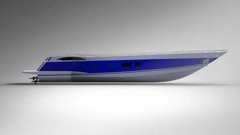
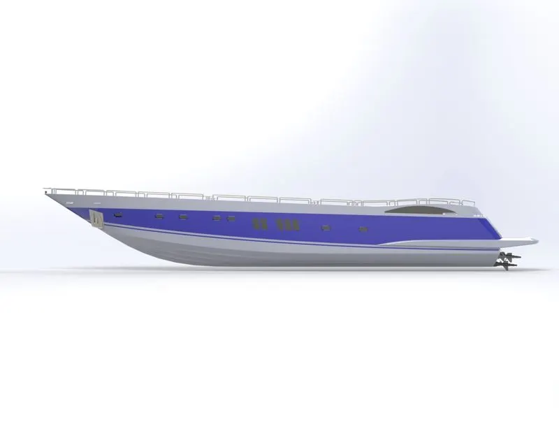
1.Hull :
-
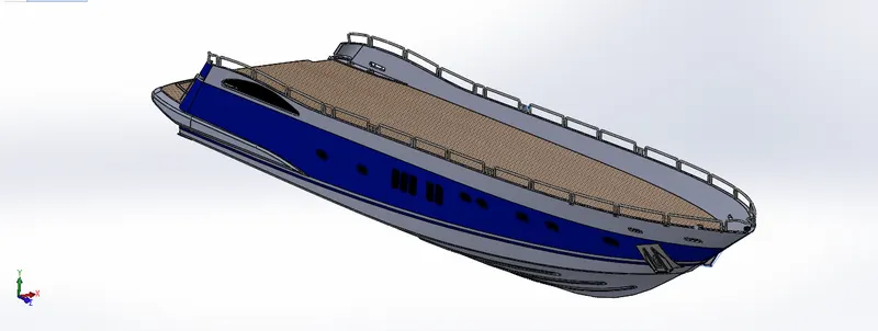
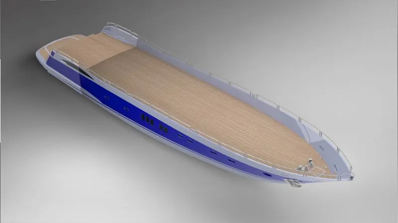
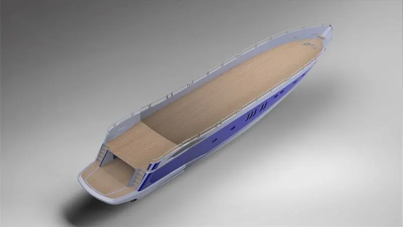
A hull is the watertight body of a ship or boat. The hull may open at the top (such as a dinghy), or it may be fully or partially covered with a deck. Atop the deck may be a deckhouse and other superstructures, such as a funnel, derrick, or mast. The line where the hull meets the water surface is called the waterline
- Features used for this model are Surface loft, Surface swept, Geometry pattern, Linear pattern, Knitting of the surfaces (providing the appropriate tolerances), Surface boundary, Filing the surface/surface fill, Mirror, 3d sketch, Projecting curve, Reference geometry by requirement, Shell (for creating the solid body), Cut extrude, Revolve, Helix, Split line, Split command, Surface offset
a. Part model image
b. Rendered image
2.Superstructure :
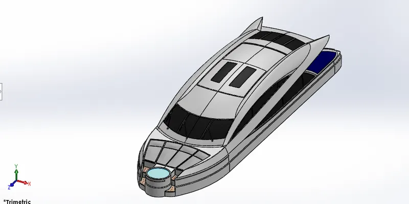
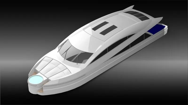
- A superstructure is an extended construction of any building or platform that rises above the rest of the building or platform in a distinct manner. Thus, superstructure means to add a construction to an already existing structure. In ships this is the name given to the part of the ship that emerges from the deck
- The size of the superstructure has a great influence on the mobility of the vessels. They are designed in a manner, so that, they add value and hinder the speed and mobility in the least.
-
The superstructure was complex thing to design in the yacht, Features used for this model are Projecting curves, Reference geometry, Swept, Surface loft, Boundary surface, Surface extends, Surface trim,Surface knitting, Surface fill, Delete face, Surface offset, Ruled surface
a. Part model image
b. Rendered image
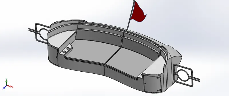
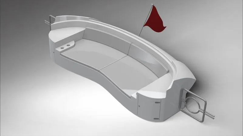
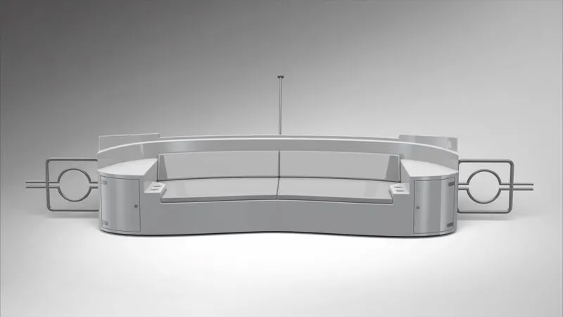
3.Frontseat, Middleseat, Rearseat :
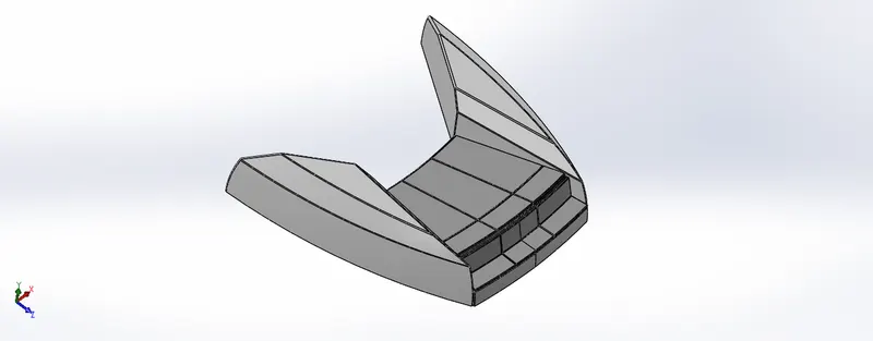
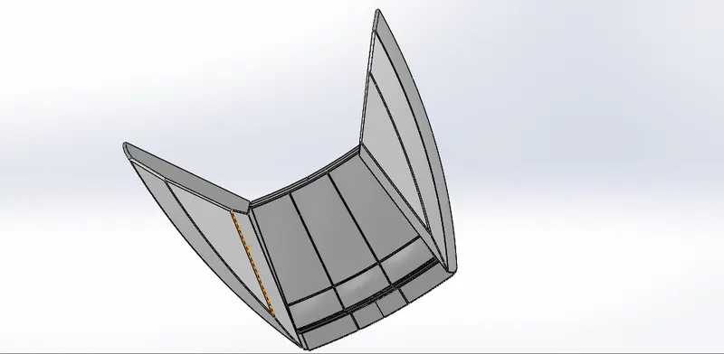
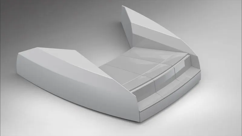
- Frontseat :
- Features used for this model are Surface Loft, Surface Sweep, Surface Extrude, Surface Fill, Surface Trim, Knit Surfaces , Boss Extrude, Revolve, Chamfer, Fillet, Dome & mirror
a. Part model image
b. Rendered image
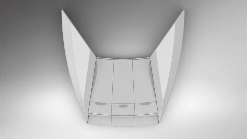
Middle seat:
- Features used for this model are Boss Extrude, Cut Extrude, Chamfer, Fillet & Mirror
a. Part model image
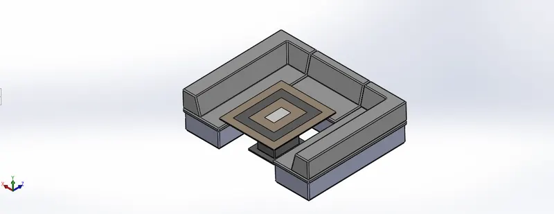
b. Rendered image
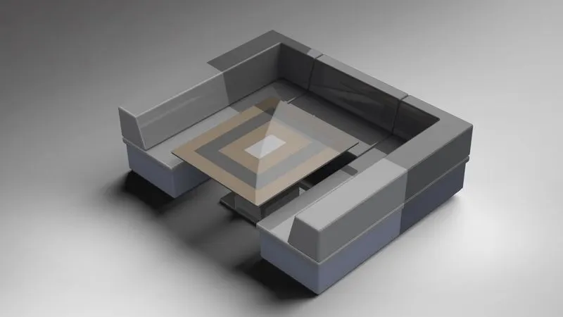
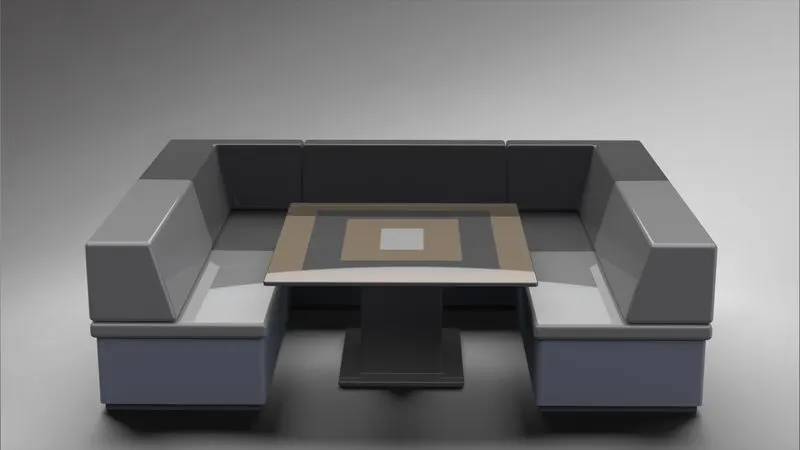
Rearseat:
- Features used for this model are Surface Loft, Sweep, Ruled Surface, Surface Sweep, Surface Extrude, Surface Fill, Surface Trim, Knit Surfaces ,Surface Offset, Boss Extrude, Revolve, Chamfer, Fillet, Dome & Mirror.
a. Part model image
b. Rendered image
4.Garage door:
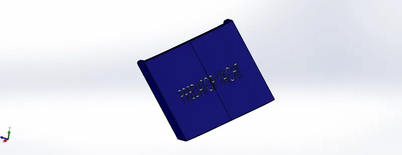
- A garage door is a large door on a garage that opens either manually or by an electric motor (a garage door opener). Garage doors are frequently large enough to accommodate automobiles and other vehicles
- Features used for this model are Cut Extrude, Shell, Fillet & Mirror.
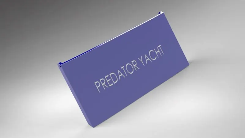
a. Part model image
b. Rendered image
5.Propeller:
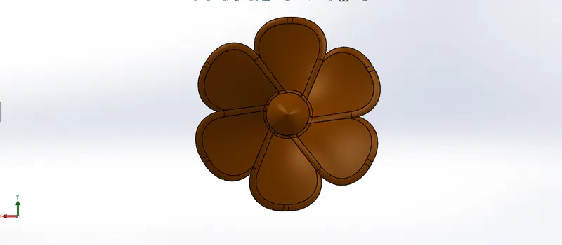
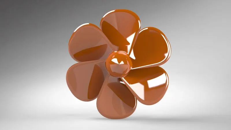
- A propeller is a device with a rotating hub and radiating blades that are set at a pitch to form a helical spiral, that, when rotated, performs an action which is similar to Archimedes' screw. It transforms rotational power into linear thrust by acting upon a working fluid, such as water or air.
- Features used for this model are Boss extrude, Revolve, circular pattern, fillet, loft, cut extrude
a. Part model image
b. Rendered image
6.Radar :
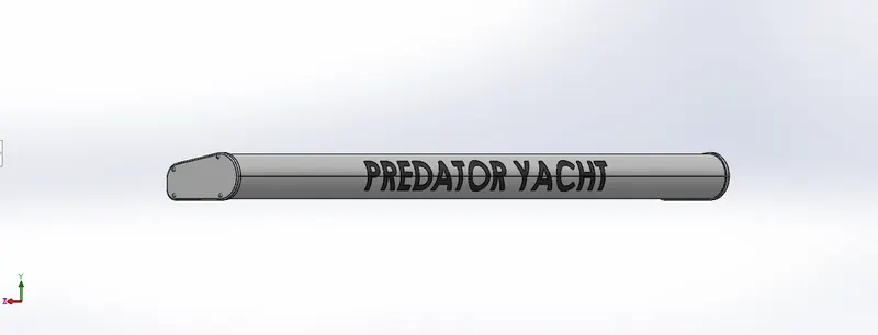
- Radar will show what is around the boat, seeing through darkness, precipitation and poor visibility. Whether you’re crossing a busy shipping channel in thick fog, looking for squalls offshore, or identifying a harbour entrance in the dark, Radar offers a significant aid to navigation and safety.
- It works by sending out a radio signal. When the signal hits an object, it gets reflected back to the radar, which can then calculate a rough estimate of the object. It does so by detecting other ships and land obstacles, to give bearing and distance for collision avoidance and navigation while on water
- Features used for this model are Boss Extrude, Cut Extrude, Mirror, Sketch Pattern, fillet and Split line
a. Part model image
b. Rendered image
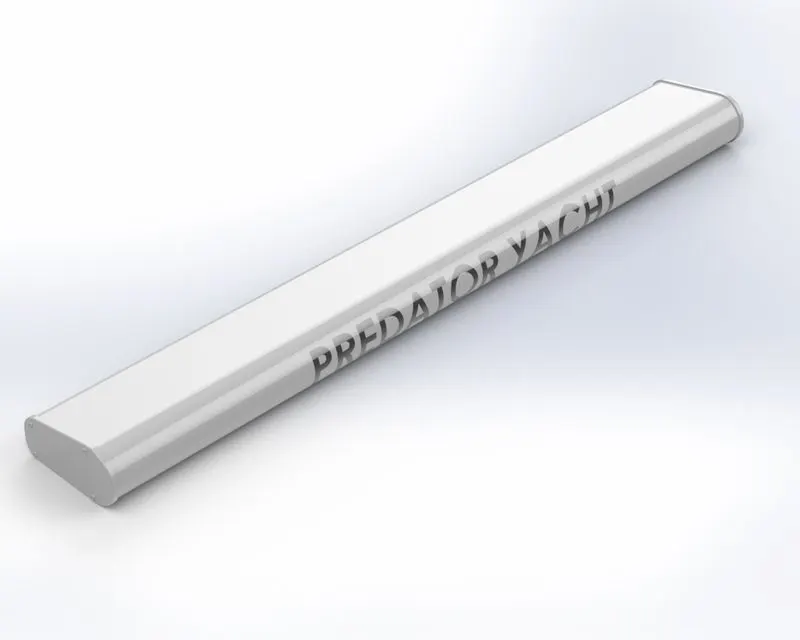
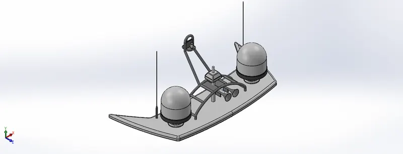
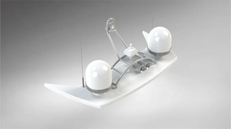
7.Radarmast :
- A radar mast is a tall spar or a hollow metal structure rising vertically from the top deck surface of the superstructure which supports the radar and its associated equipments such as the antennas and horns.
- Features used for this model are Boss Extrude, Cut Extrude, Revolve, Sweep, Chamfer, Fillet, Dome & Mirror.
a. Part model image
b. Rendered image
ASSEMBLY OF PREDATOR YACHT
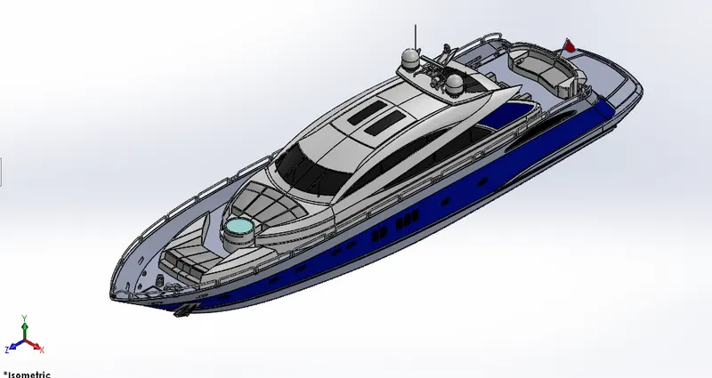
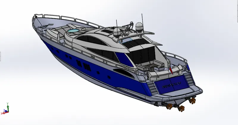
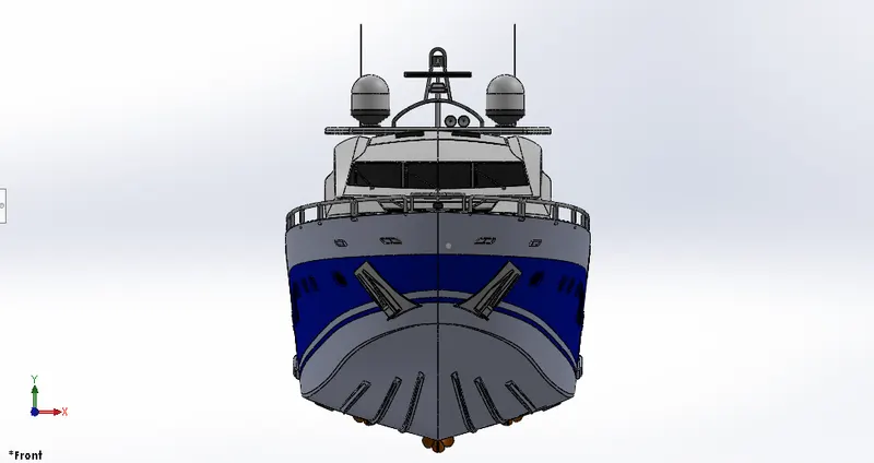
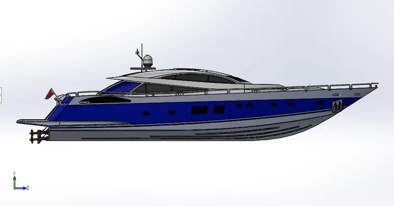
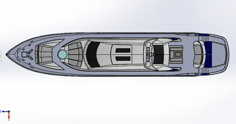
- All the parts were assembled in a Solidworks Assembly file by inserting each part, one after the other using suitable mate relations.
1.Mates: Mates create geometric relationships between assembly components. As you add mates, you define the allowable directions of linear or rotational motion of the components. You can move a component within its degrees of freedom, visualizing the assembly's behavior. Some of the mates used during the assembly process are coincident, distance, angle, concentric, parallel, width, limit angle
RENDERING OF PREDATOR YACHT
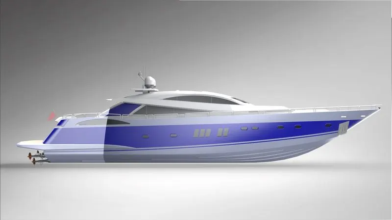
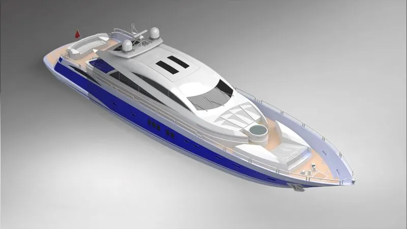
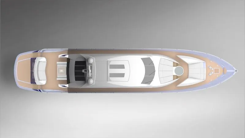
SOLIDWORKS Visualize allows you to leverage your 3D CAD data to create photo-quality content in the fastest and easiest way you can from images to animations, interactive web content, and immersive Virtual Reality. Bring your products to life. SOLIDWORKS Visualize is the “camera” for your CAD data
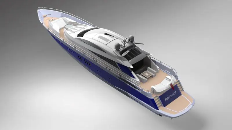
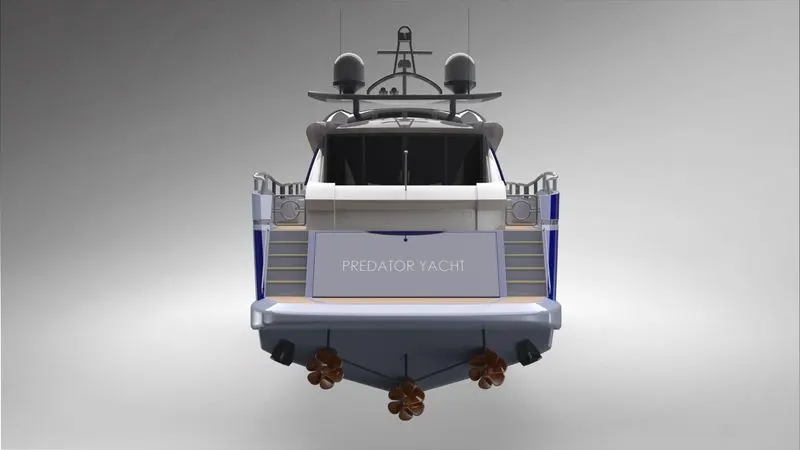
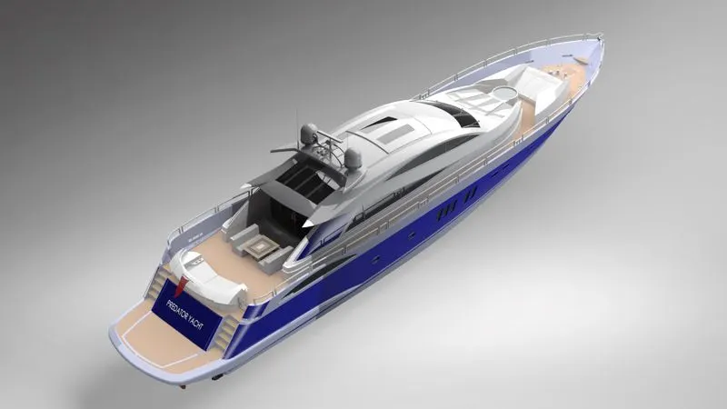
Some of the rendered images are shown below

CONCLUSION
Based on this design of model & assembly i have concluded that i have successfully learnt to use surfce and solid modelling features and also learnt to render the model using photoview 360.