Roof Design
Objectives:
- For the given roof styling develop the essential flanges and reinforcements.
- Create the ditch area with an opening angle of 3 degrees.
- Perform curvature study and calculations for the position of the bow roof.
Introduction:
Roof Panel
It is the outer panel at the top of the vehicles which protects the passengers from rain, dust, sun, and other external elements.
The roof panel is generally a flat panel-like component and, according to this particular embodiment is made from light-weight aluminum material and includes an outer periphery. Depending on the particular embodiment, roof panel may have cut-outs for items like sunroofs or windows, it may have longitudinal ribs, creases, or other aerodynamic features, or it may be made from a single panel or multiple panels that are joined together
In order to provide significant weight savings for the vehicle, it is preferable that at least 75% of the surface area of roof assembly be comprised of the aluminum-based roof panel; however, this is not necessary. In one embodiment, the roof panel is made from an aluminum-based alloy that is comprised of Al, Si, Cu, Fe, Mn, and Mg; more specifically, the roof panel may be made from an aluminum-based alloy that includes 0.8% Si, 0.9% Cu, 0.4% Fe, 0.4% Mn, 0.7% Mg and Al as the remainder.
The size and shape of the attachment flange can vary depending on the particular application, but it is generally designed to allow for a weld or braze seam that attaches roof assembly to the structural members without the need for additional mechanical fasteners like self-piercing rivets (SPR) or adhesive compounds.
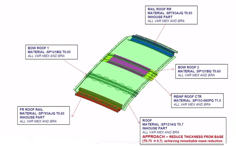
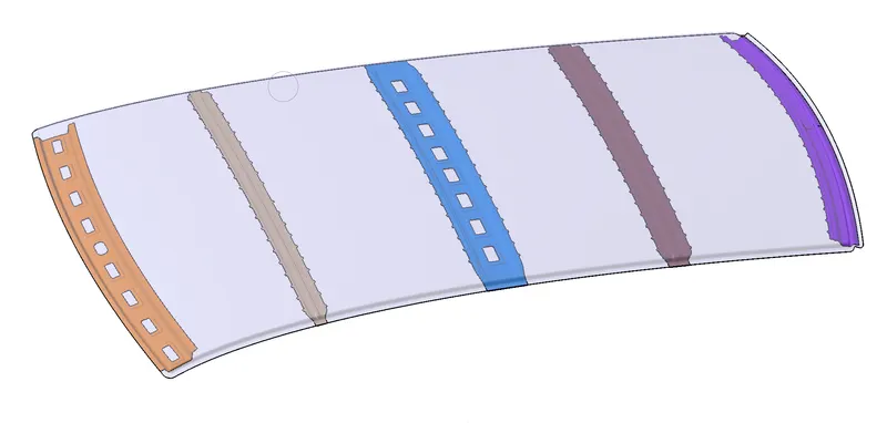
Roof assembly Consist of
- Roof outer panel
- Front Roof Rail
- Bow roofs
- Center Reinforcement Roof rail
- Rear Roof Rail.
Design Concept Sheet (DCS)
This sheet contains all the information regarding the roof design such as material, the thickness of the part, manufacturing regions and to which region is the part is to be used.
Front Roof Rail
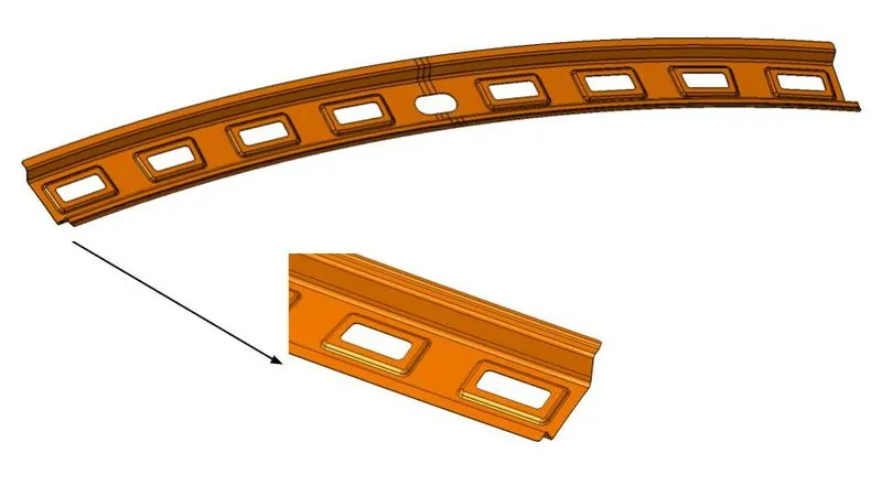
It is an additional part given to the roof as a reinforcement which includes supports for the features such as bracket lamp and room lamp which is being mounted on this rail.
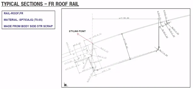
From the styling surface, we obtain the styling point from which the flange opening angle should be 3 degrees for the deep drawing manufacturing situations with a length of 21.5 mm.
This 21.5mm is considered based on the mounting considerations as follows:
- Windshield glass
- Rubber paste
- Sealant between the windshield and front roof rail for the leak proof.
The opening angle of 3 degrees is important as it determines the draw ability of the part and also affects the visibility criteria.
The depth of the front roof rail should be in accordance with the visibility criteria line.
The length of the front roof rail should be in accordance with the minimum headroom clearance.
If the driver sits closer to the steering wheel then the length of the front roof rail will be lesser and if the driver sits away from the steering wheel the length of the front roof rail will be larger.
The minimum fillet radius to be given is 3mm+thickness of the component.
The thickness of the front roof rail is in the range of 0.65-0.75 mm since the front roof rail is made from body side outer scrap.
The one end of the front roof rail is attached to the ditch area of the roof by spot welds and the other end of the front roof rail is attached to the roof with the help of mastic sealants.
Rear Roof Rail
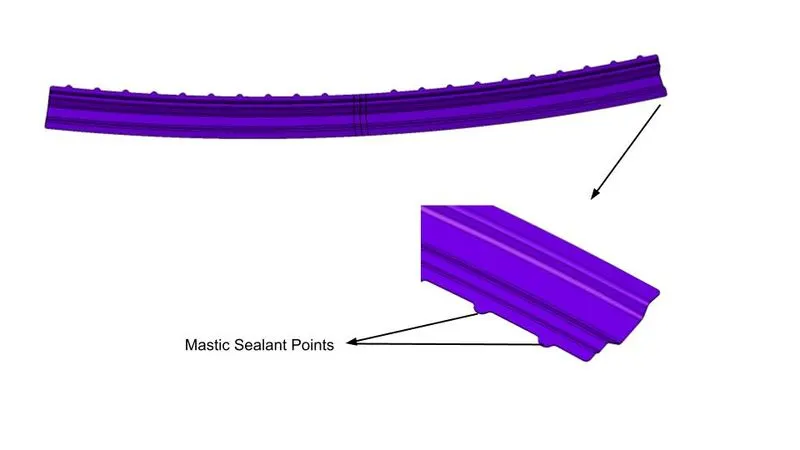
For the rear roof rail as well there are headroom clearance criteria to be followed as in the front roof rail.
The master section of the rear roof rail is different compared to the other roof rail because of the back door attachment.
The hinge of the back door and sealant for the leak roof is also attached to the rear roof rail hence there is a change in the master section when compared to the other roof rails.
Similarly, the design considerations for the rear bow roof should satisfy the minimum headroom clearance and the minimum fillet radius and draft angle to be given for the feasibility of manufacturing.
The mastic sealants.
Sealants are used to close the gap between two or more substrates. It also acts as a leakproof between the components. It forms a barrier through the physical properties of the sealant itself and by adhesion to the substrate.
Mastic Sealants are used to join one surface to another or protect the area to which it is applied. It has heat-resistant properties and the ability to form a strong bond which is applied using a mastic sealant gun.
Mastic Sealants have an influence area of 80mm diameter.
Centre Reinforcement Rail
Centre roof rail is provided to effectively support the flat area of the roof as it is more susceptible to failure under the action of the load. Usually, the center reinforcement roof rail will be placed at the center of the roof connecting the B pillar support structure which results in added support in the roll-over test.
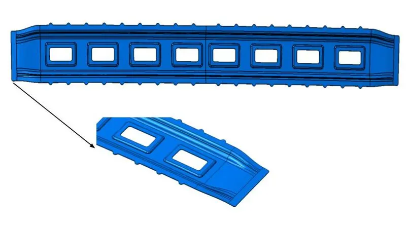
The thickness of the center bow roof is 1.5mm thickness. Embossments are created at the rail in order to increase the strength of the roof rail and beads are given to decrease the material usage while retaining the strength of the rail.
Bow Roof 1 & 2
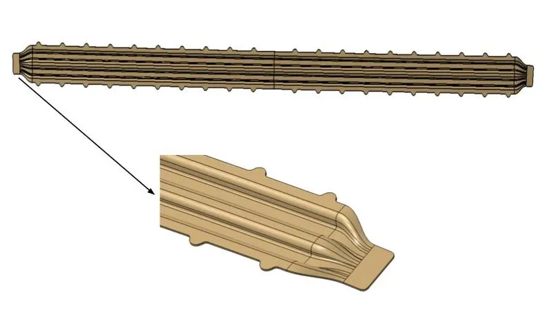
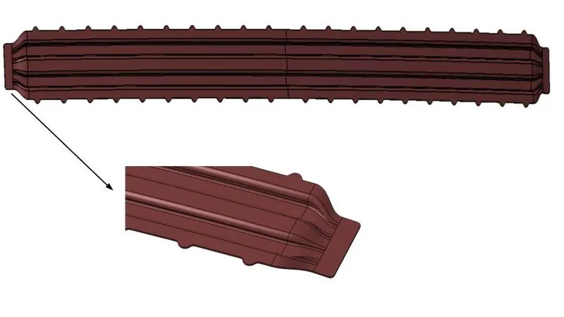
The bow roof is given for the same reason as the center reinforcement. The cross-section area of the bow roof is less compared to the center reinforcement and also the thickness of the bow roof is 0.65mm --0.75 mm.
The bow roof position is fixed tentatively and then arranged according to the heat distortion and snow load criteria.
The bow roofs are fixed to the roof with the help of mastic sealants on both sides. With the use of mastic sealants, the strength of the bow roof is increased.
Bow Roof 1
Bow Roof 2
Roof Crush Test
The validation for the designed roof is the roof crush test in which the test sample is placed horizontally as shown in the figure below
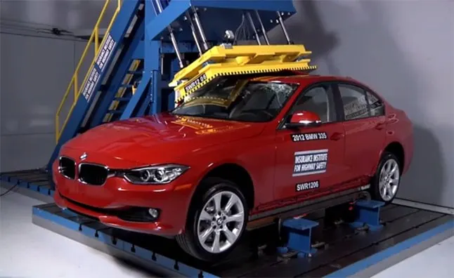
The windows and doors of the test sample are closed and locked and the force is applied at a 5-degree angle with respect to the horizontal in the side view and 25-degree angle with respect to the horizontal in the front view.
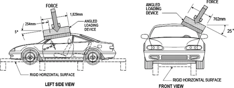
From the above test, the load-displacement graph is obtained and if the displacement is more than required then necessary reinforcement should be added to reduce the displacement.
Validation for the position of the bow roof
1. Heat Distortion criteria.
Metal softens and deforms when its temperature is higher than the saturation temperature. This study is done to check the ability of the roof to withstand the temperature distortion with respect to their position which contributes to the increased length.
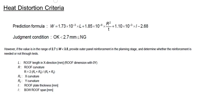
Table 1:
| Sl. No. | BOW's | Rx | Ry | R | I | L | t | R^2/t | W | Remarks |
| 1 | FR & 1st | 5744.239 | 1920.98 | 2879.126672 | 355.855 | 2025.621 | 0.75 | 11052493.86 | 1.420235966 | OK |
| 2 | 1st & CNTR | 5069.61 | 5772.291 | 5398.179558 | 431.622 | 2025.621 | 0.75 | 38853790.06 | 2.017903646 | OK |
| 3 | CNTR & 2nd | 3906.368 | 10830.832 | 5741.825522 | 391.207 | 2025.621 | 0.75 | 43958080.43 | 2.067876518 | OK |
| 4 | 2nd & RR | 3169.163 | 15067.779 | 5236.870052 | 450.33 | 2025.621 | 0.75 | 36566410.59 | 1.996165926 | OK |
2. Snow load Prediction criteria
This study is done to check the strength of the roof to withstand the snow load and return to its original position without any permanent deformation.
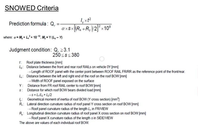
Table 2:
| Sl. No. | BOW's | Iy | My | a | Lx | Ly | y | L1 | L2 | s | Rx | Ry | t | Qr | Remarks |
| 1 | FR & 1st | 926.7 | 678012.5421 | 0.8280246074 | 1105.103 | 1980.795 | 440.057 | 440.057 | 526.869 | 483.463 | 4549.412 | 2547.544 | 0.75 | 10.34120077 | OK |
| 2 | 1st & CNTR | 6019 | 766028.5377 | 0.7695332877 | 1002.285 | 1980.795 | 526.869 | 526.869 | 490.158 | 508.5135 | 3755.742 | 5688.878 | 0.75 | 38.79787912 | OK |
| 3 | CNTR & 2nd | 1385 | 730647.6506 | 0.6960829925 | 976.06 | 1980.795 | 490.158 | 490.158 | 523.711 | 506.9345 | 4260.33 | 10927.18 | 0.75 | 3.828655287 | OK |
| 4 | 2nd & RR | 1001.702 | 1980.795 | 523.079 | 3940.753 | 16686.775 | 0.75 | #DIV/0! |
From the Table 1 & 2, we can infer that the heat distortion criteria and snow load criteria are satisfied.
If in case one of the bow roofs does not satisfy which has a remark NG, which describes the position of the bow roof is incorrect and it fails for the heat distortion and snow load condition.
In order to satisfy the above criteria, the position of the bow roof can be changed to a flat area in the roof, and also the addition of embosses on the roof panel can be done.
If the criteria are still not satisfied change in the curvature of the roof is proposed to the styling team.
Section Modulus
Section modulus is a geometric property for a given cross-section used in the design of beams or flexural members.
There are two types of section moduli, the elastic section modulus, and the plastic section modulus.
Elastic Section Modulus
The elastic section modulus is used, applying up to the yield point for most metals and other common materials.
Plastic Section Modulus
The plastic section modulus is used for materials where elastic yielding is acceptable and plastic behavior is assumed to be an acceptable limit. Designs generally strive to ultimately remain below the plastic limit to avoid permanent deformations, often comparing the plastic capacity against amplified forces or stresses.
Significance of Section Modulus:
1. Higher the section Modulus lesser will be the bending stress produced. Greater will be its load-bearing capacity.
Section modulus is denoted by Z
`Z = I/(y_(max))`
where I is the moment of inertia
and `y_max` is the maximum distance between the extreme ends.
From Bending Equation, we have
`sigma / y = M/I = E/R`
`sigma` is bending stress produced in a beam at a distance y from the neutral axis.
M is the bending moment
I is the moment of inertia
E is the modulus of Elasticity
R is the radius of Curvature.
From section modulus we have,
`sigma = M/ (I/y_max) = M/Z`
From the above equation, we can infer that the higher the section modulus lesser will be the bending stress produced in the beam greater will be its load-bearing capacity.
Hence if max bending stress produced in the beam is less then the beam will not fail as the difference between max bending stress produced in the beam is and the permissible stress is more.
Section Modulus for Front roof rail
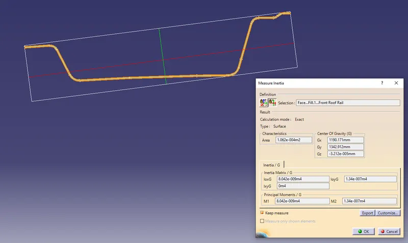
`I_y = 8.042xx10^-9 m^4 = 8042 mm^4`
`l= 57.899mm`
`Z = 8042/57.899 =138.89 mm^3 `
Section Modulus for Rear Roof Rail
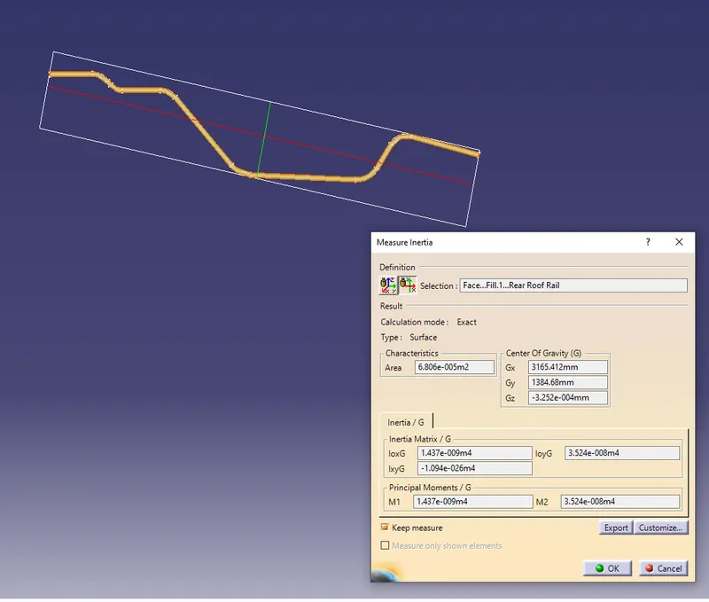
`I_y = 1.437xx10^-9 m^4 = 1437 mm^4.`
`l = 77.21mm`
`Z = 1437/77.21 = 18.611 mm^3`
Section Modulus for Bow Roof 1
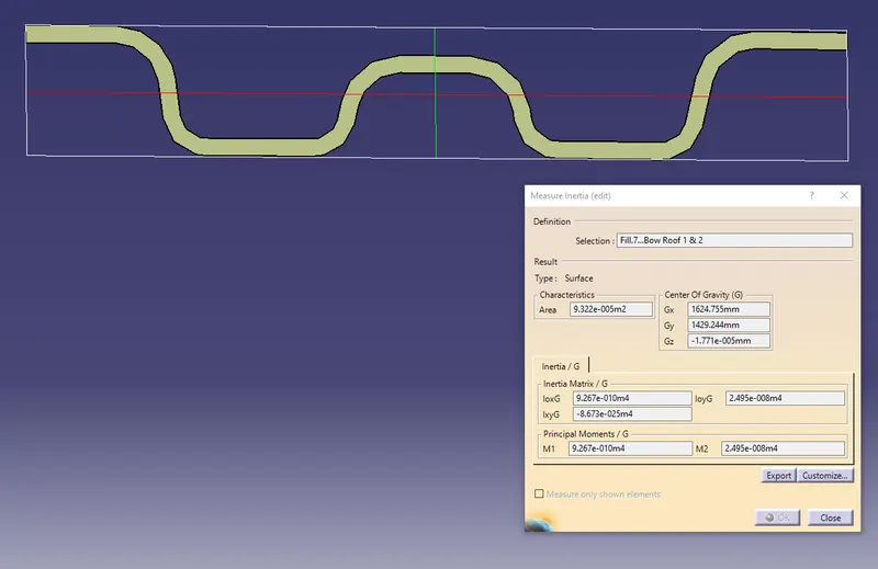
`I_y = 9.267xx10^-10 m^4 = 926.7 mm^4`
`l = 57.899 mm`
`Z = 926.7/57.899 = 16.005mm^3`
Section Modulus for Bow Roof 2
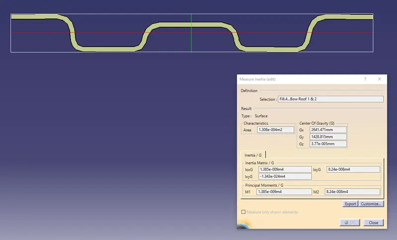
`I_y = 1.385xx10^-9 m^4 = 1385 mm^4`
`l = 88.015 mm`
`Z = 1385/88.015 = 15.735mm^3`
Section Modulus for Centre Reinforcement
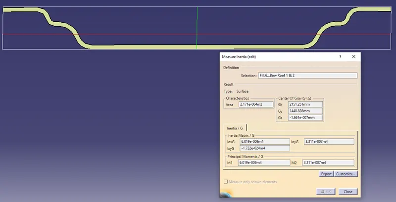
`I_y = 6.019xx10^-9 m^4 = 6019 mm^4`
`l = 132.943 mm`
`Z = 6019/132.943 = 45.27 mm^3`
Draft Analysis.
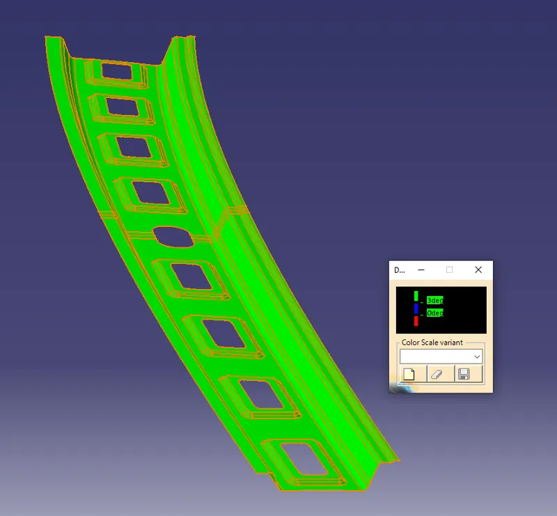
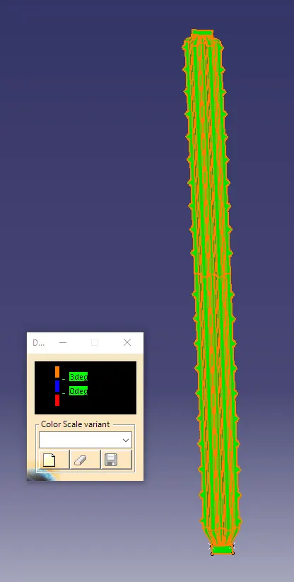
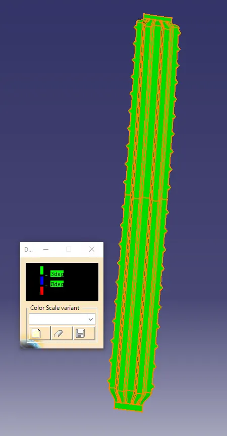
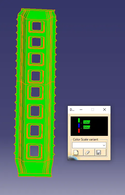
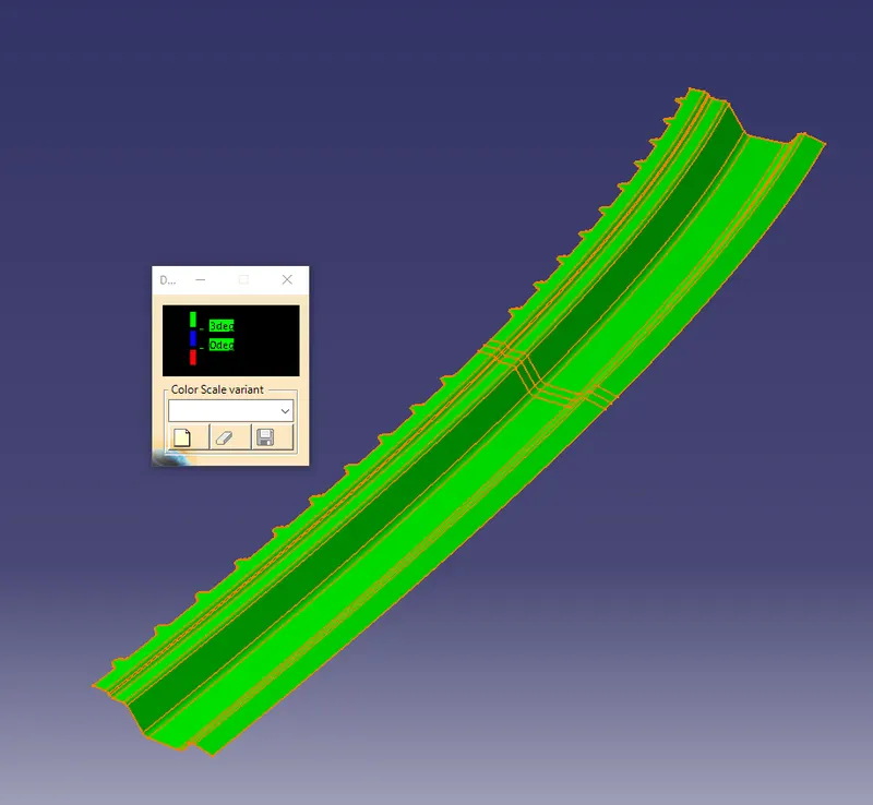
Draft analysis is performed to check if the designed part is easily ejected with the help of ejector pins. A minimum draft angle of 3 degrees is given to the faces of the part which are perpendicular to the tooling direction.
The green color indication describes that the part is clearing for the draft angle .i.e, the faces are greater than 3 degrees with respect to the draft direction and the blue color describes the faces are perpendicular to the tooling direction, and the red color indicates the faces have negative tooling direction.
Draft analysis for the front roof rail
Draft Analysis for the Bow roof 1 & 2
| Bow Roof 1 | Bow Roof 2 |
 |
 |
Centre Reinforcement Roof Rail
Rear Roof Rail
Roof Assembly
Section of the Roof Assembly
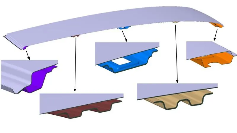
From the above figure, we can infer that a gap of 3 mm is maintained between the bow roof and the roof plate for the mastic sealants, and a gap of 0.05mm is given at the front end and rear end of the front and rear roof rail respectively due to the spot welds.
Conclusion:
1. The front and rear roof rail is designed according to industry standards.
2. The position of the bow roofs and center reinforcement are in accordance with the curvature study.
3. Draft analysis is performed to check for the ease of manufacturing of the part.