Roof challenge
Aim: For the Given Roof styling, create an ASSEMBLY by developing the essential flanges for the outer roof and creating the reinforcements.
Solution:
An Automobile roof or car top is the portion of an automobile that sits above the passenger compartment, protecting the vehicle occupants from sun, wind, rain, and other external elements. Because the earliest automobiles were designed in an era of horse-drawn carriages, early automobile roofs used similar materials and designs. In later years, many variations on the automobile roof developed. These include:
- Convertible roofs
- Hardtops
- Sunroofs
- T-tops
- Targa tops
- Vinyl roofs
Obligatory standards are dictated to vehicle manufacturers for decreasing the number of road death tolls in rollover crashes. Simultaneously, demands to produce lightweight vehicles have increased substantially to reduce toxic gas emissions.
International environmental regulations and fuel efficiency demands in developed countries are continually putting pressure on the automotive industry. For fuel efficiency improvement, weight-reduction technologies are relatively easy to apply and have the advantage of applying to both existing internal combustion engine vehicles and futuristic vehicles. Weight is a core factor that determines vehicle fuel efficiency; weight reduction is also associated with various other design issues, including structural rigidity, aerodynamic design, braking system, and CO2 reduction.
Among vehicle collision accidents, damage caused by head-on collisions has typically led to the most severe injuries to occupants; however, such collisions have shown a decreasing trend over time by various safety technologies. However, loss of human life owing to vehicle rollover has shown an increasing trend. Furthermore, during head-on collisions, the bumper and engine parts are deformed themselves, and the collision energy is absorbed to reduce the shock and injury experienced by the occupants. However, in the case of a rollover, the external impact is transferred directly to the occupant space, which leads to fatal injuries. In particular, rollover crashes are serious safety problems for lightweight vehicles.
Roof parts
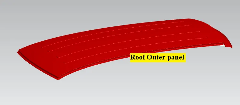
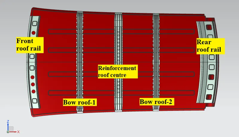
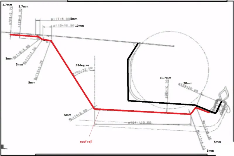
Master section followed for Front roof rail:
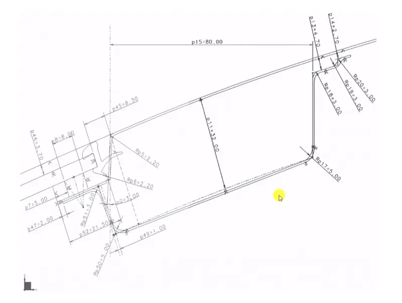
Master section followed for Rear roof rail:
The thickness of roof parts considered while designing is,
| Location | Value |
| Roof Outer sheet | 0.75mm |
| Front roof rail | 0.75mm |
| Bow-roof 1 | 1.25mm |
| Roof center rail | 1.5mm |
| Reinforcement roof | 1.2mm |
| Bow-roof 2 | 1.5mm |
| Rear roof rail | 0.75mm |
The positions of the Bow-roofs are checked by Bow–roof prediction formula & Snow load prediction formula
Bow–roof prediction formula:
`W = [1.73 × 10^(-3) × L] + [1.85 × 10^(-8) × (R^2)/t] + [ 1.10×10^(-3) × l] - 2.68`
Judgment Condition : OK< 2.7> 3.1
Where
L = Roof Length in X-Direction[mm](Roof dimension in 0-Y)
R = Roof curvature ; `R = 2(Rx × Ry)/(Rx+Ry)`
Rx = X curvature
Ry = Y curvature
t = Roof plate thickness [mm]
l = Bow Roof Span [mm]
Steps followed:
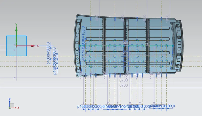
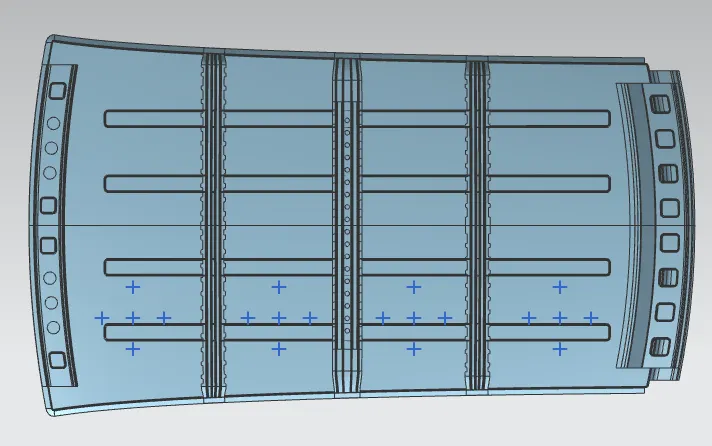
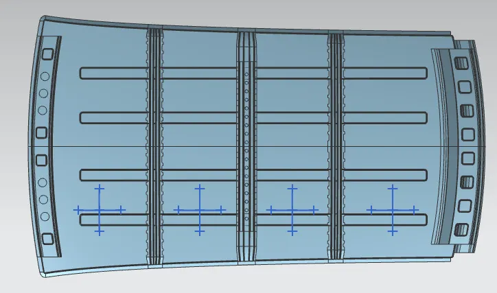
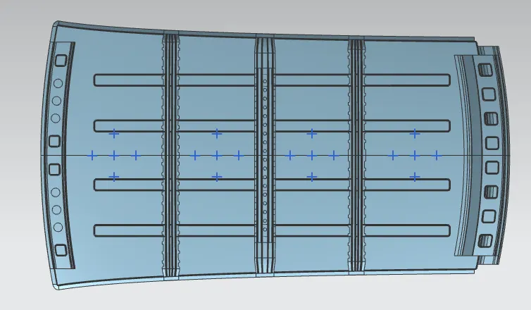
- From the 0-Y axis, at -3Y (300mm), the reference line is drawn parallel to the O-Y axis line. Then 100 mm lines are offset to either side of the -3Y line. Centerlines are drawn between each adjacent roof rail edge respectively and are offset by 100mm on either side. Intersection points are marked in the sketch. All the geometry is in construction lines except for the points.
- Intersection points are projected onto the roof surface.
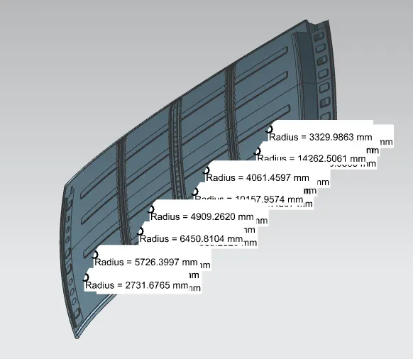
- Projected points are joined using an arc curve and the minimum radius is measured.
Table
| S.No | Bows | Rx | Ry | R | l | L | t | W | OK/NG |
| 1 | FR & 1st | 5726.3997 | 2731.6765 | 3698.8722 | 440.7957 | 2033.7048 | 0.75 | 1.660665 | OK |
| 2 | 1st & CTR | 4909.262 | 6450.8104 | 5575.4431 | 345.9225 | 2033.7048 | 0.75 | 1.985601 | OK |
| 3 | CTR & 2nd | 4061.4597 | 10157.9574 | 5802.7884 | 334.7789 | 2033.7048 | 0.75 | 2.037151 | OK |
| 4 | 2nd & RR | 3329.9863 | 14262.5061 | 5399.343 | 451.6525 | 2033.7048 | 0.75 | 2.054232 | OK |
From the above table, it can be seen that the Bow-roof positions have passed the judgment conditions of the Bow-roof prediction formula.
Snow load prediction formula:
`Qr = [Iy × t^2] / [α × s × [(Rx + Ry)/2]^2 × 10^-8]`
Judgment condition: Qr ≥ 3.1
Where
`α = My × Lx^2 × 10^-12` ; `My = Y(Ly-Y)`
t = Roof plate thickness [mm]
Ly = Distance between the front and rear roof Rails on the Vehicle along with 0Y[mm]
Length of Roof panel with the center point between Roof rail Front /Rear as the front and rear reference point.
Lx = Distance between the Left and Right end of the roof on the Roof BOW [mm]
Width of the roof panel is exposed on the surface.
Y = Distance front Front Roof Rail to Roof BOW[mm]
s = Distance for which Roof BOW bears divided load [mm] ; `s = (L1 + L2)/2`
Iy = Geometrical moment of inertia of Roof BOW (Y cross-section )[mm4]
Rx = Lateral direction curvature radius of roof panel Y cross-section on Roof BOW [mm]
Roof panel curvature Radius of the Length Lx in Front view
Ry = Longitudinal Direction curvature radius of the Roof panel X cross-section on Roof BOW [mm]
Roof panel X curvature radius of length s in Side view
Today, the snow load damage test is mainly used to decide on the roof panel's style and thickness. This test is much more important for a light commercial vehicle (LCV) because LCV has a bigger roof area, a more straight style and as a result of these two properties, it has a heavier roof panel than the other vehicle. Moreover, simulation is quite difficult and its tolerance is not less than 15 % because of not only the panel's post-buckling behavior and material nonlinearity but also deformations on the panel which highly depend on the manufacturing process.
Steps followed:
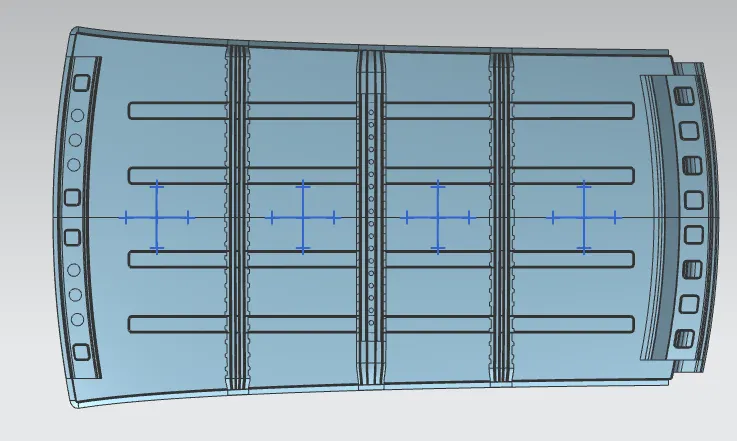
- 100 mm lines offset to either side of the 0-Y axis line. Centerlines are drawn between each adjacent roof rail edge respectively and are offset by 100mm on either side. Intersection points are marked in the sketch. All the geometry is in construction lines except for the points.
- Intersection points are projected onto the roof surface.
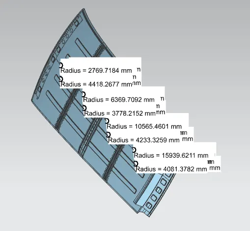
- Projected points are joined using an arc curve and the minimum radius is measured.
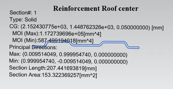
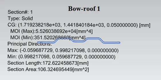
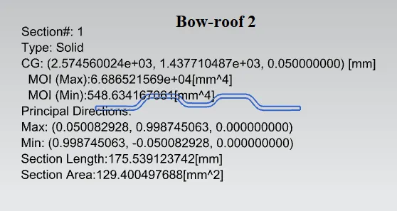
- The moment of inertia of the bow roofs and center reinforcement roofs are determined along O-Y cross-sectional plane.
Table
| S.No | Bows | Iy | Lx | Ly | Y | alpha | L1 | L2 | s | Rx | Ry | t | Qr | OK/NG |
| 1 | FR & 1st | 351.5202 | 1137.0198 | 2033.7048 | 440.7957 | 0.9077461 | 537.8 | 433.3 | 485.55 | 4418.2677 | 2769.7184 | 0.75 | 3.473122 | OK |
| 2 | 1st & CTR | 587.4991 | 1088.0868 | 2033.7048 | 345.9225 | 0.6912296 | 433.3 | 422.2 | 427.75 | 3778.2152 | 6369.7092 | 0.75 | 4.341331 | OK |
| 3 | CTR & 2nd | 548.6341 | 1063.6965 | 2033.7048 | 334.7789 | 0.6435288 | 422.2 | 593.7 | 507.95 | 4233.3259 | 10565.4601 | 0.75 | 1.724345 | NG |
| 4 | 2nd & RR | 1048.2173 | 2033.7048 | 451.6525 | 0.7851053 | 593.7 | 4081.3782 | 15939.6211 | 0.75 | #DIV/0! |
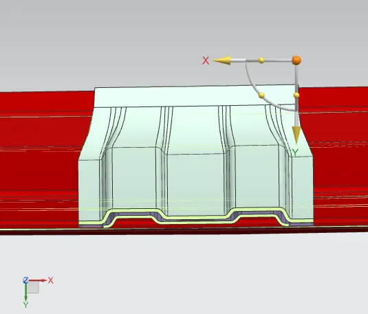
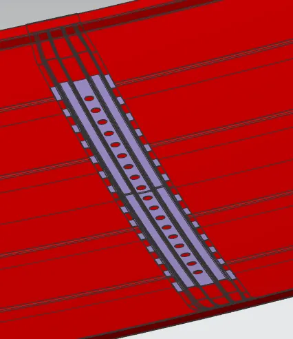
From the above table, it is observed that the Reinforcement roof center and Bow-roof2 positions have not cleared the judgment condition of the snow load prediction formula. To compensate for this problem, embosses on roof outer surfaces are provided and also extra reinforcement is placed between the outer roof and reinforcement center roof. This extra reinforcement will also help in providing strength during rollover car crashes.
Draft Analysis:
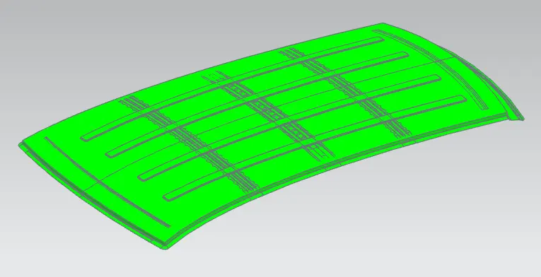
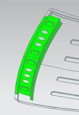
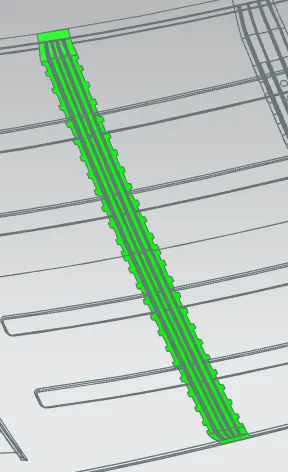
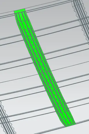
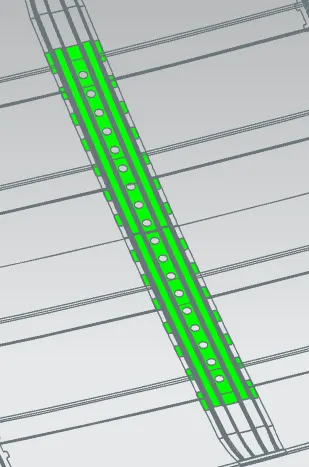
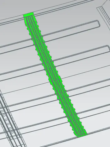
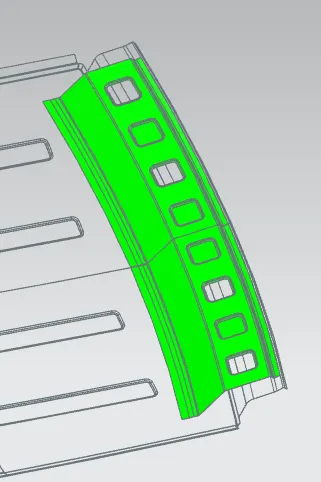
For fabrication of parts from sheet metal, because of tool accessibility, a draft is maintained while designing sheet metal components. A positive draft means the angle of the face w.r.t the direction of pull, is more than the reference angle. A negative draft means the angle of the face, w.r.t the direction of the pull, is less than the negative reference angle. Each component is checked for a minimum positive draft of 7 degrees. The green color indicates that it has cleared the minimum draft requirement.
Section Modulus:
Section modulus is a geometric property for a given cross-section used in the design of beams or flexural members. Other geometric properties used in the design include an area for tension, the radius of gyration for compression, and the moment of inertia for stiffness. Any relationship between these properties is highly dependent on the shape. There are two types of section moduli, the elastic section modulus (S) and the plastic section modulus (Z). For general design, the elastic section modulus is used, applying up to the yield point for most metals and other common materials.
The elastic section modulus is defined as`S = I/y`
where,
'I' is the second moment of area (or moment of inertia)
'y' is the distance from the neutral axis to any given fiber.
It is often reported using `y = c`, where 'c' is the distance from the neutral axis to the most extreme fiber.
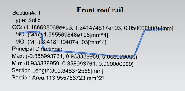
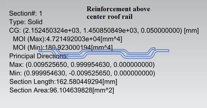
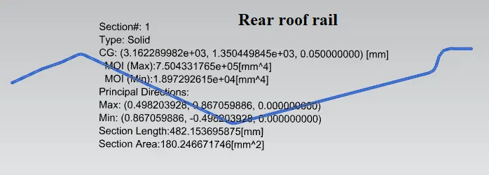
Images for Bow-roof 1&2, center roof rail are at Snow load prediction study
Table for section modulus of all components
| Location | The second moment of Inertia,' I' (mm^4) | Distance from the neutral axis to extreme fiber, 'y' (mm) | Section modulus, 'S' |
| Front roof rail | 8418.119 | 521.9739 | 16.12 |
| Bow-roof 1 | 351.52 | 574.7033 | 0.55 |
| Roof center rail | 587.499 | 558.6596 | 1.05 |
| Reinforcement center | 180.923 | 400.4 | 0.45 |
| Bow-roof 2 | 548.634 | 550.4164 | 0.99 |
| Rear roof rail | 18972.926 | 461.7492 | 41.08 |
Roof strength test
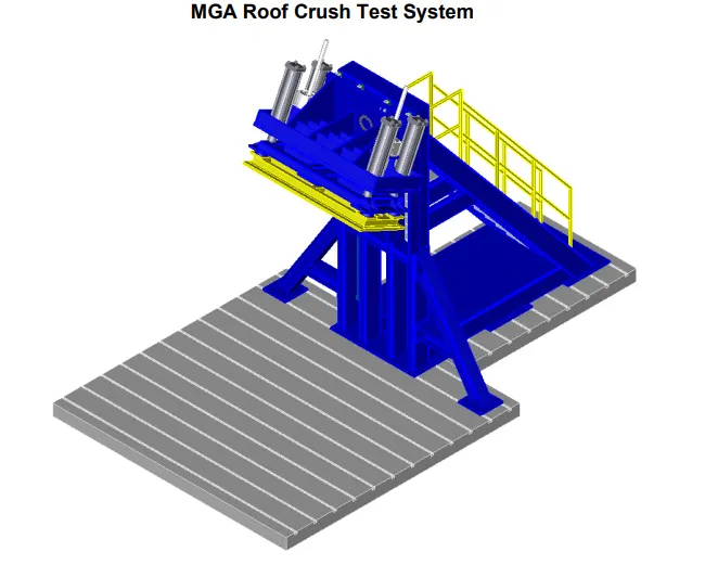
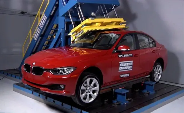
In the test, the strength of the roof is determined by pushing an angled metal plate down on one side of the roof at a slow but constant speed and measuring the force required to crush the roof. The force applied relative to the vehicle's weight is known as the strength-to-weight ratio. The peak strength-to-weight ratio recorded at any time before the roof is crushed 5 inches is the key measurement of roof strength.
A good rating requires a strength-to-weight ratio of at least 4. In other words, the roof must withstand a force of at least 4 times the vehicle's weight before the plate crushes the roof by 5 inches. For an acceptable rating, the minimum required strength-to-weight ratio is 3.25. For a marginal rating, it is 2.5. Anything lower than that is poor.
Conclusion: The above challenge was successfully completed as per the given requirement.