Roof challenge
AIM:
For a Given Roof styling, creating an ASSEMBLY by developing the essential flanges for the outer roof and creating the reinforcements.
OBJECTIVE:
- Provide appropriate dimensions and check for Draft analysis.
- Do a curvature study on the roof and perform calculations to determine the position of the Bow-roofs.
- Suggest and implement remedies in the design if the criterion is not full-filling
- To calculate the heat distortion and snow-loading criteria
INTRODUCTION:
An automobile roof or car top is the portion of an automobile that sits above the passenger compartment, protecting the vehicle occupants from sun, wind, rain, and other external elements. Because the earliest automobiles were designed in an era of horse drawn carriages early automobile roofs used similar materials and designs.
An automobile roof consists of the following parts:
- Outer panel
- Front Roof Rail
- Bow roof Rail
- Center Roof Rail
- Rear Bow roof Rail
- Rear Roof Rail
DESIGN CRITERIA FOR THE ROOF:
- Visibility criteria
- Head Clearence
- Curvature study
- Heat Distortion and Snow-Loading Criteria
- Draft Analysis
- Safety Parameters
DESIGNING THE ROOF:
OUTER PANEL
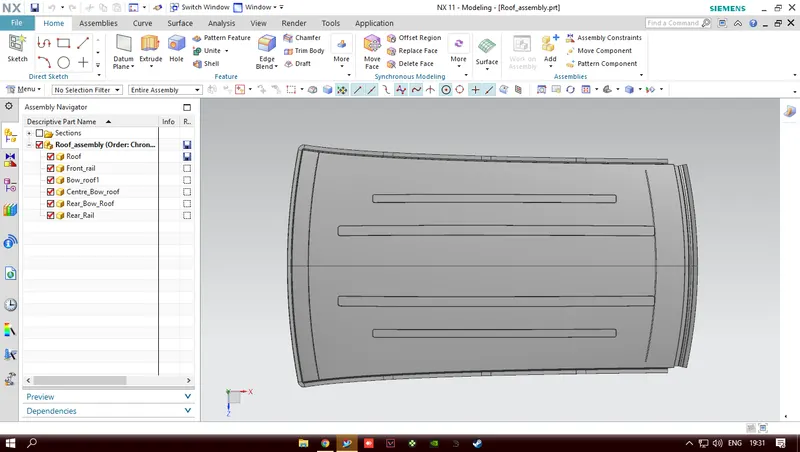
The outer panel is the outermost part of the roof of an automobile. It is the aestyhetic part of a car. This is the part which sits above the passengers compartment. It protects the passengers from dust, wind, rain, snow, hail, etc.
For this challenge, a roof skin has been given to us which is then extracted into an assembly file and the designing is done based upon that skin data.
FRONT ROOF RAIL
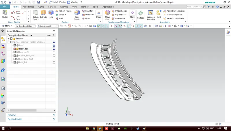
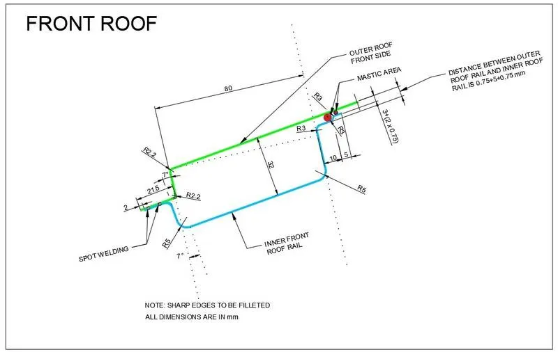
The front rail underpins the rooftop external shell at the front end. It is mounted with a support rooftop rail fortification on the two closures. The front roof rails have certain area which we have trimmed and provided emboss to increase the strength as well as reduce the overall weight. The one end of the front rail is joined with the outer panel by spot welding and rest of the part is joined by mastic sealants. We also have taken into consideration the headroom clearence and visibility criteria while designing this part.
REAR ROOF RAIL
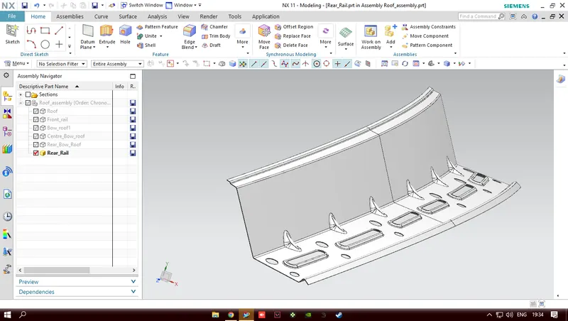
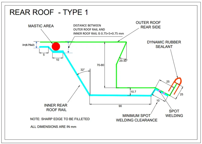
It is the support which is joined to the backdoor and the body side outer and inner panels. Just like the front roof rail, we have tkaen into consideration the headroom clearence and the visibility criteria. The rear roof rail just as the front roof rail have certain area trimmed off just to reduce the overall weight and hasve been given embosses to increase the overall strength. Designing the rear roof rail is purely dependent on its provided master section as the backdoor opening trajectory depends on this part. Just like the front roof rail, the part where the backdoor will be connected is spot welded with the oter panel, and the other end is joined with mastic seals.
BOW ROOFS
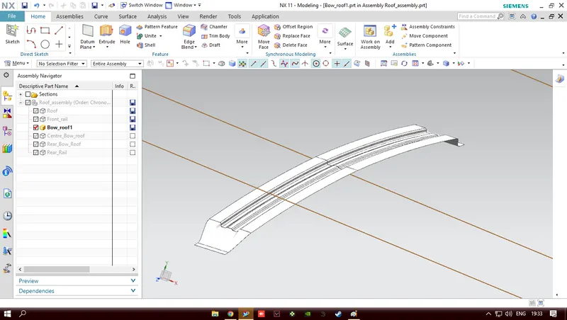
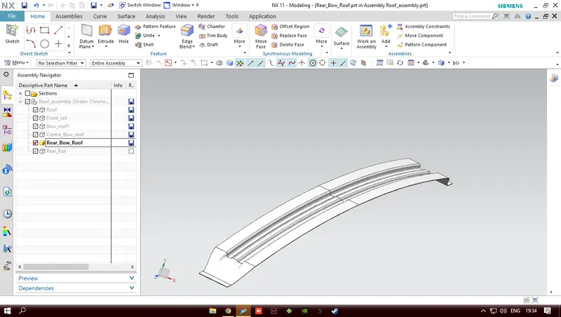
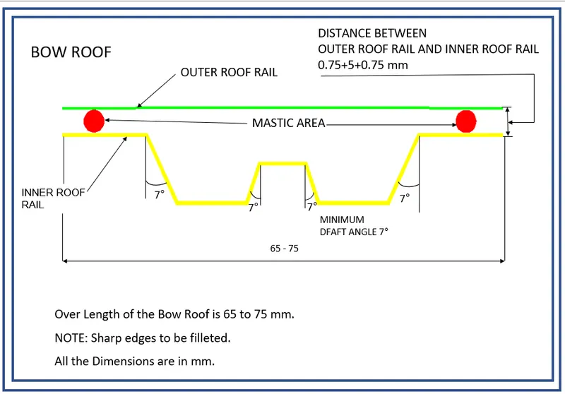
The bow roofs are given to improve the tortional stiffness and load bearing capacity of the roof. The number of bow roofs designed or provided to the roof depends upon the overall size and dimension of the roof. The longer the roof, more number of bow roofs are provided to the BIW frame. The y are attached to the outer panel by mastic sealents. Each mastic points will have 80mm circular effective area. This is because when the panel is heat treated, the mastic will increase in a radial direction ultimately joining both the oter panel and the bow roof together.
CENTRE BOW ROOF
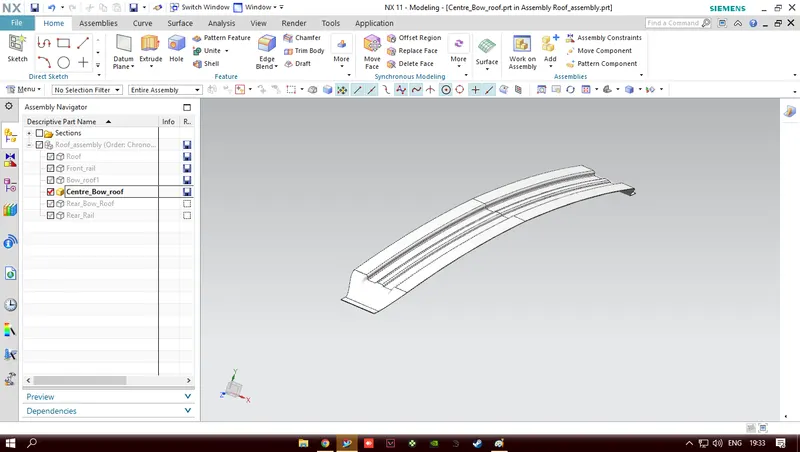
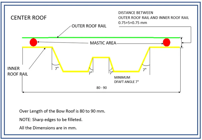
The centre roof rail is provided exclusively to provide strength to the flat area of the roof as it is more susceptible to fail under the action of load. Usually the centre roof rail will be placed at the centre of the roof connecting the B pillar support structure which provides added support in the roll over test. Just like the two other bow roofs, the centre bow roof will be attached to the roof outer panel by mastic sealents.
CURVATURE STUDY OF THE ROOF:
The heat distortion study plays an important role in sheet metal design. The heat distortion temperature is a temperature limit above which the material cannot be used in structural applications. This study is use to predict at swhich temperature the materials softens when exposed to fixed load at an elevated temperature. In order to reduce the damage on the roof, based on this study, this will help us to better understand the bow roof positioning to strengthen the roof.
Bow–Roof Prediction Formula
W = [1.73 x 10^(-3) x L] + [1.85 x 10^(-8) x (R^2)/t] + [ 1.10x10^(-3) x l] - 2.68
Judgment Condition
OK< 2.7
Where,
L = Roof Length in X-Direction[mm](Roof dimension in 0-Y)
R = Roof curvature
R = 2(Rx*Ry)/(Rx+Ry)
Rx = X curvature
Ry = Y curvature
t = Roof plate thickness [mm]
l = Bow Roof Span [mm]
Roof length = 2061.3302
Rx and Ry curvature
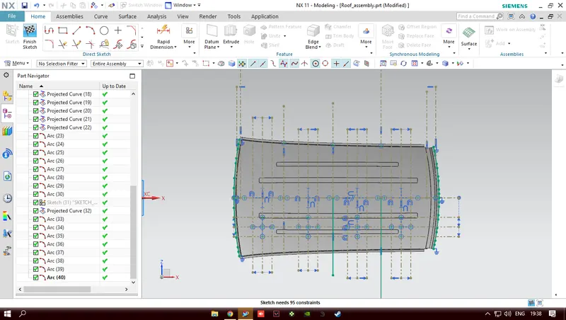
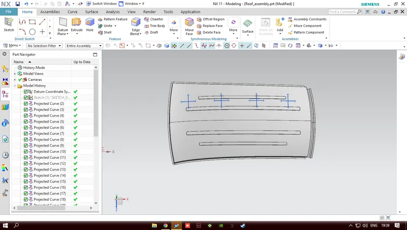
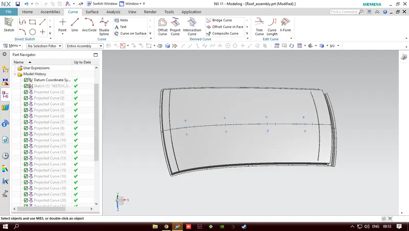
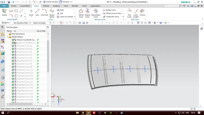
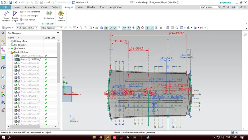
- From 0-Y axis at 3y distance 300mm line is drawn parallel on the perpendicular plane. After that 100mm lines are drawn on either side of the 3y line. Now centre lines are drawn between each adjacent rail roof edges respectively. Intersection points are marked on the sketch.
- Project the intersection points in the sketch of the roof surface.
- Join the projected curves using arc curve and measure the minimum radius and linear dimensions.
- Then after all this we put the values in the formula and Calculate 'W'.
Heat Distortion Calculation:
W = [1.73 x 10^(-3) x L] + [1.85 x 10^(-8) x (R^2)/t] + [ 1.10x10^(-3) x l] - 2.68
R = 2(Rx*Ry)/(Rx+Ry)
| Roof Rails | Rx(mm) | Ry(mm) | Rx*Ry | Rx+Ry | R(mm) | L(mm) | t(mm) | I(mm) | W | Results |
| FR to BOW 1 | 5740.33 | 2416.55 | 13871794.5 | 8156.88 | 3401.25 | 2061.3302 | 0.75 | 372.7330 | 0.955 | ok |
| BOW 1 to CR BOW | 5001.60 | 6081.56 | 30417530.5 | 11083.16 | 5488.96 | 2061.3302 | 0.75 | 435.6078 | 1.0082 | ok |
| CR to Rear BoW | 4009.61 | 10409.5 | 41654759.3 | 14419.11 | 5789.26 | 2061.3302 | 0.75 | 421.5152 | 1.014 | ok |
| Rear Bow to RR | 3323.84 | 14355.186 | 47714341.4 | 17678.18 | 5397.84 | 2061.3302 | 0.75 | 348.1387 | 0.995 | ok |
From the above results, it can be concluded that all values of W is less than 2.7. Which states that all the bow roof position designing are good and OK
Snow Load Prediction Formula
Snow loading formula helps to check the durability of the roof to withstand snowfall and get back to its original shape without any deformation once the snow is removed.
Qr = [Iy x t2] / [α x s x [(Rx + Ry)/2]2 x 10-8]
Note: The Qr value given over here is correct. There was a typo error in the formula given in the video.
Where,
α = My x Lx2 x 10-12 , My = Y(Ly-Y)
t = Roof plate thickness [mm]
Ly = Distance between the front and rear roof Rails on the Vehicle along with 0Y[mm]
Length of Roof panel with the center point between Roof rail Front /Rear as the front and rear reference point.
Lx = Distance between the Left and Right end of the roof on the Roof BOW [mm]
The width of the roof panel is exposed on the surface.
Y = Distance front Front Roof Rail to Roof BOW[mm]
s = Distance for which Roof BOW bears divided load [mm]
s = L1/2 + L2/2
Iy = Geometrical moment of inertia of Roof BOW (Y cross-section )[mm4]
Rx = Lateral direction curvature radius of roof panel Y cross-section on Roof BOW [mm]
Roof panel curvature Radius of the Length Lx in Front view
Ry = Longitudinal Direction curvature radius of the Roof panel X cross-section on Roof BOW [mm]
Roof panel X curvature radius of length s in Side view
Rx and Ry curvature
- From 0-Y axis at 3y distance 300mm line is drawn parallel on the perpendicular plane. After that 100mm lines are drawn on either side of the 3y line. Now centre lines are drawn between each adjacent rail roof edges respectively. Intersection points are marked on the sketch.
- Project the intersection points in the sketch of the roof surface.
- Join the projected curves using arc curve and measure the minimum radius and linear dimensions.
- Then after all this we put the values in the formula and Calculate 'Qr'.
Snow Load Prediction Formula
Snow loading formula helps to check the durability of the roof to withstand snowfall and get back to its original shape without any deformation once the snow is removed.
Qr = [Iy x t2] / [α x s x [(Rx + Ry)/2]2 x 10-8]
α = My x Lx2 x 10-12 , My = Y(Ly-Y)
s = L1/2 + L2/2
Apllying all these formulas to get Qr
| Roofs | Rx | Ry | L1 | L2 | Lx | Ly | Y | Iy | My | α | S | Qr | RESULTS |
| FR+BR1 | 4612.8 | 2487.2 | 446.90 | 510.54 | 1135.52 | 1929.54 | 446.90 | 372.70 | 662591.8 | 0.854 | 478.72 | 4.06 | PASSED |
| BR1+CR | 3760.06 | 5987.8 | 510.54 | 496.45 | 1097.23 | 1929.54 | 957.44 | 465.62 | 930727.42 | 1.12 | 503.50 | 1.95 | FAILED |
| CR+BR2 | 4026.26 | 10871.67 | 496.45 | 475.63 | 1077.21 | 1929.54 | 1453.90 | 379.89 | 691532.99 | 0.802 | 486.04 | 0.987 | FAILED |
The values of Qr should be greater than or equal to 3.1. But In the tests we can see that only case 1 has passed and case 2 and case 3 has failed. So in this case we can do is to ask the styling team to modify the bow roofs.
Also the other case is we can provide embosses to the surface as shown below:
SECTION MODULUS
Section modulus is the geometric property for a given cross-section used in the design or beams or flexual members. Other geometric properties used in the design includes an area for tera and shear , the radius of gyration for compression, and the moment of inertia, and the polar moment of inertia for stiffness.Any relationship between these properties are highly dependent on the shape. There are 2 types of section modulus:
- Elastic Section Modulus
- Plastic Section Modulus
We are going to talk about Elastic Ssection Modulus.
The formula for Elastic Section Modulus is
S =I/Y
where,
S is the section modulus
I is the second moment of area( not to be confused with moment of inertia or area moment of inertia)
Y is the distance from the nuetral axis from the given fiber's exterme end.
To get the Section modulus, we first create an intersection curve using the datum csys and then go to sketch, project the intersection curve and then hide the intersection curve and finish the sketch. After that we go to section analysis and select the projected curve to get the section modulus.
BOW ROOF 1:
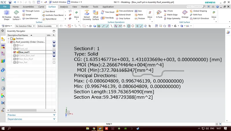
MIN(MOI) = 372.7011 mm^4
Y = 35mm
Therefore S = 372.7011/35 = 10.6486
CENTRE ROOF
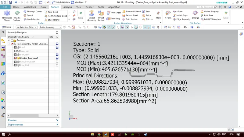
MIN(MOI) = 465.6265 mm^4
Y = 40mm
Therefore S = 465.6265/40 = 11.66
REAR BOW ROOF
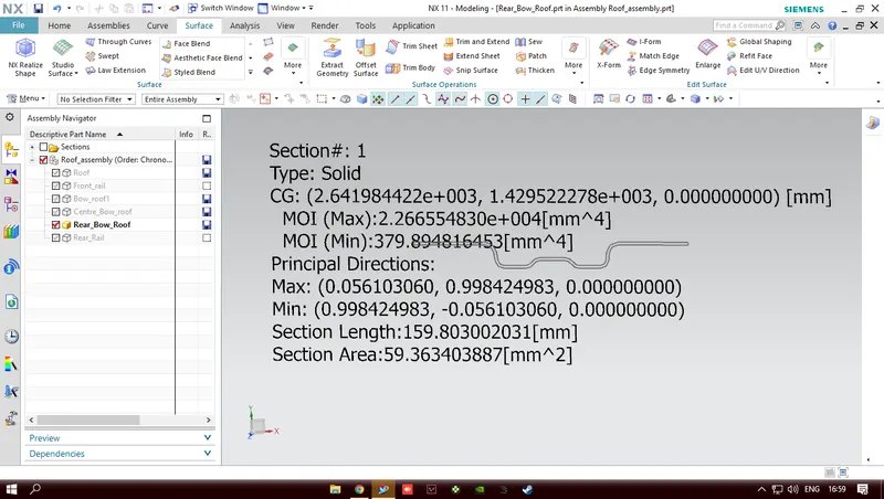
MIN(MOI) = 379.8948 mm^4
Y = 35mm
therefore S = 379.8948/35 = 10.85
FRONT ROOF RAIL
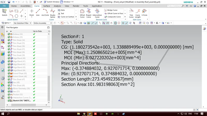
MOI(MIN) = 6.02722*10^3 mm^4
Y = 54.42
Therefore S = 6.02722*10^3/54.42 = 110.75
REAR ROOF RAIL
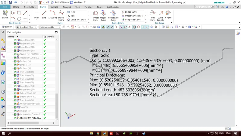
MIN(MOI) = 4.555*10^4 mm^4
Y = 92.55mm
Therefore S = 4.555*10^4/92.55 = 492.116
DRAFT ANALYSIS
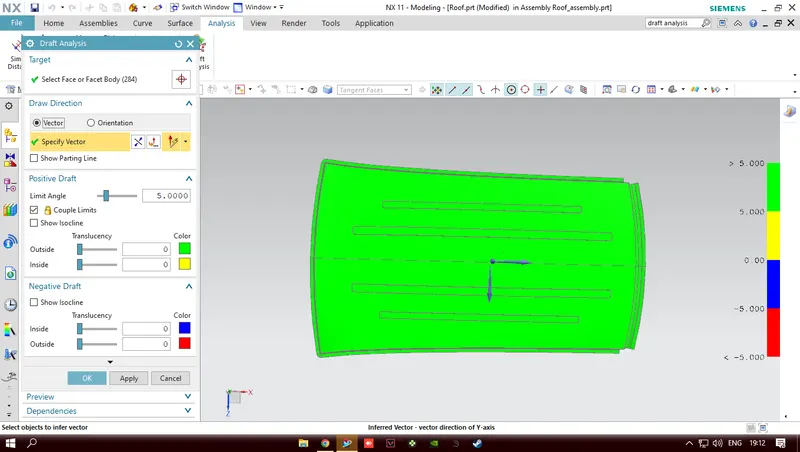
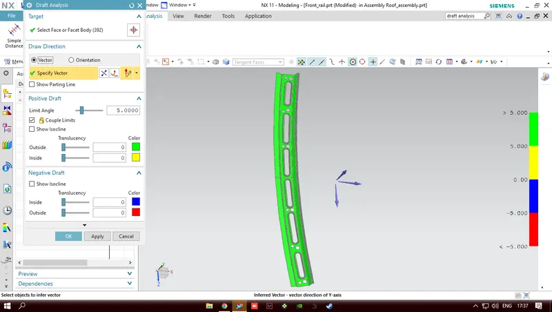
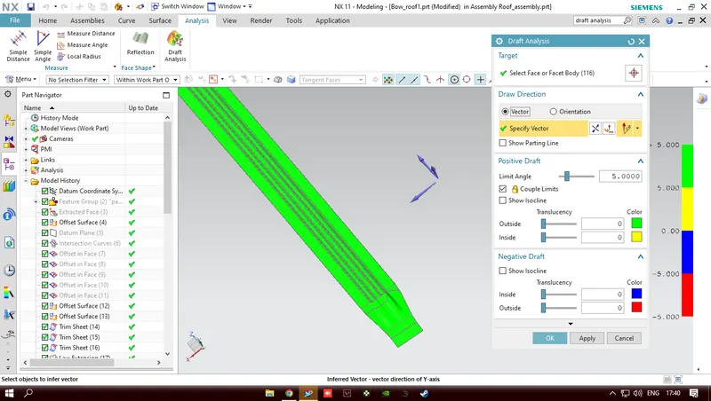
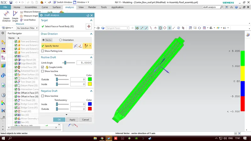
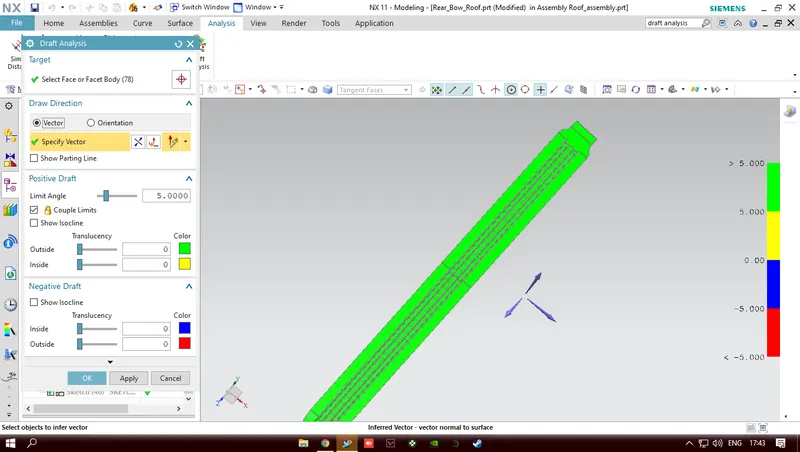
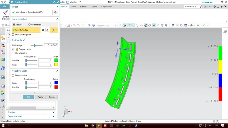
The draft analysis command enables us to check if the parts drafted by us will be easily removed. This type of analysis is performed based on color ranges identifying zones on the analysed element where the deviation from the draft direction at any point corresponds to specified values.
A minimum of 7 degree is taken foe draft analysis. The green colou depicts that all the face along the tooling direction have positive draft greater than 7 degree.
OUTER ROOF PANEL
FRONT ROOF RAIL
BOW ROOF 1
CENTRE BOW ROOF
REAR BOW ROOF
REAR ROOF RAIL
CONCLUSION:
- THE DESIGN OF THE ROOF, INNER ROOF RAILS AND THE BOW ROOFS ARE DONE ACCORDING TO THE MASTER SECTION PROVIDED TO US IN THE CHALLENGE.
- HEAT DISTORTION ANALYSIS DONE
- SNOW LOADING CRITERIA DONE
- SECTION MODULUS IS DONE
- DRAFT ANALYSIS DONE