Roof challenge
Design and development of a car roof assembly
OBJECTIVE
The aim of this project is to model a Roof Panel of Car from the Roof Styling Surface. The Project report deals with the design of essential flanges and reinforcements followed by detailed study about draft analysis, Section Modulus Report. Finally, Roof Curvature Study is done to position those reinforcements to improve the strength of the Roof to withstand Snow load and Roof Crush.
DESIGN METHODOLGY
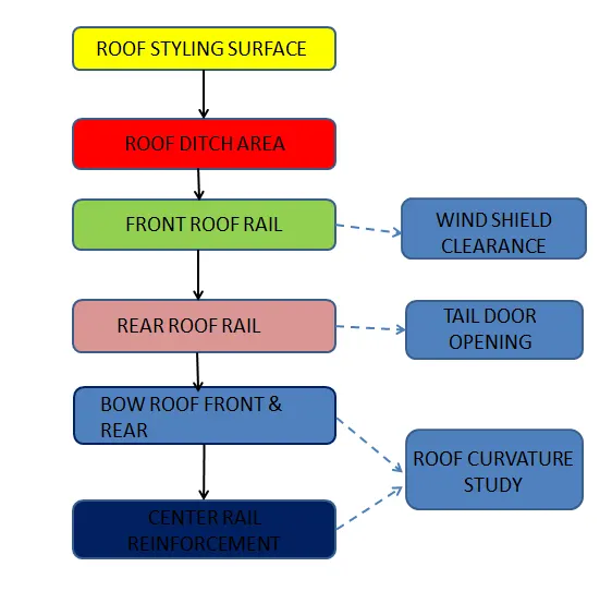
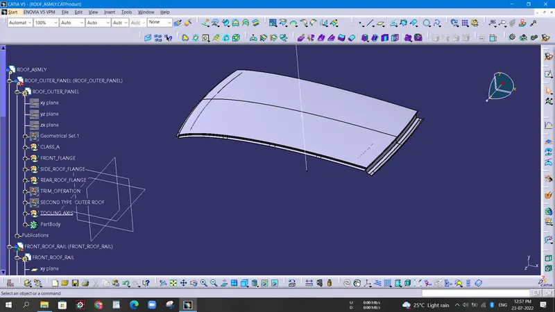
ROOF PANEL
Roof is an integral part of BIW component and holds a major factor in weight reduction of the car and safety of the passengers in cabin. The styling of roof generally requires in depth analysis of different aspects
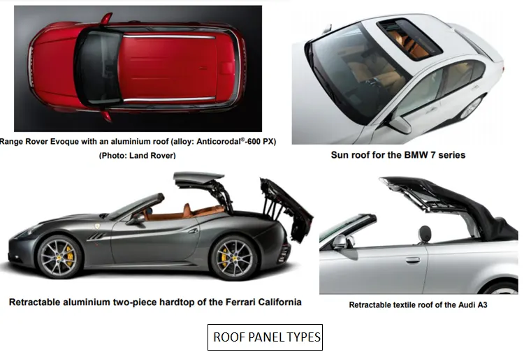
Introduction:
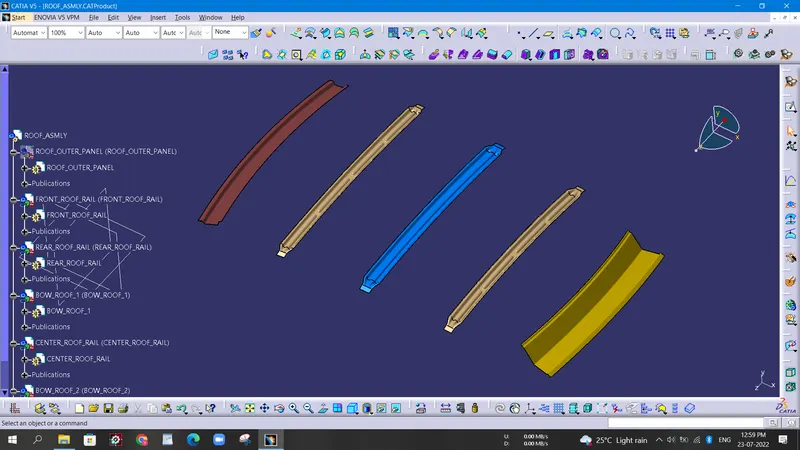
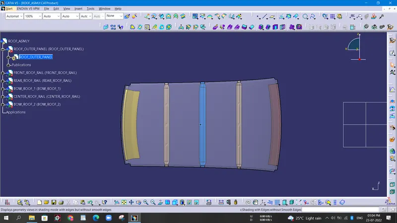
An automobile roof is considered as an integral part of BIW (body in white) design. A car roof is responsible for protecting the passenger from rain, wind, sunlight, accidents etc. It also offers aerodynamic support to the car when it is in motion. A roof panel assembly includes a roof outer panel/ditch area and inverted hat like reinforcements rails which underlie the outer side edges of the roof outer panel. Roof rails are provided to give strength to the outer panel and also provide support to other commodities present in a car.
There are different rail reinforcements in a roof panel like:
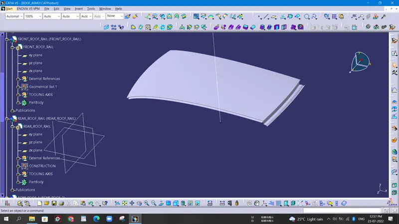
- Front roof rail
- Rear roof rail
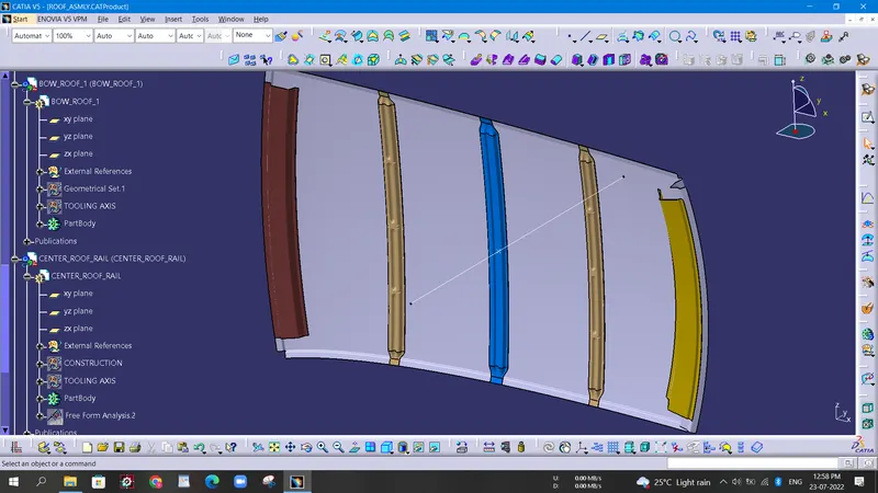
- Bow roofs
Reinforcement roof centre
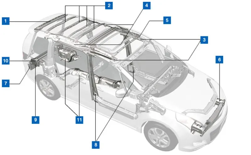
Fig 1 Car Roof Components
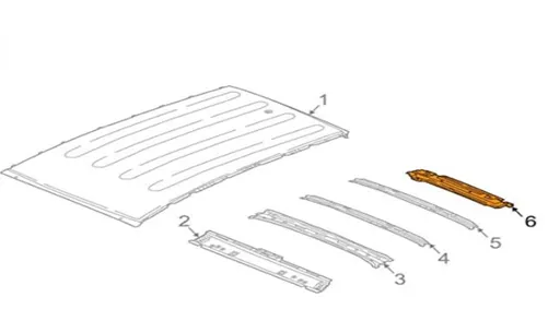
Fig 2 Roof panel with rail reinforcements
Software used : CATIA V5
Given : Roof SkinStyling surface Design Procedure
1. Styling surface cleanup :
It is necessary to remove any discontinuity in the styling surface which may result in faulty surfaces.Also it helps to generate smooth surfaces while performing complex operations. Surfaces were extracted from the given styling data and untrimmed to get the original surface back.
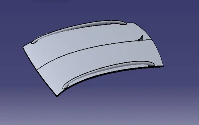
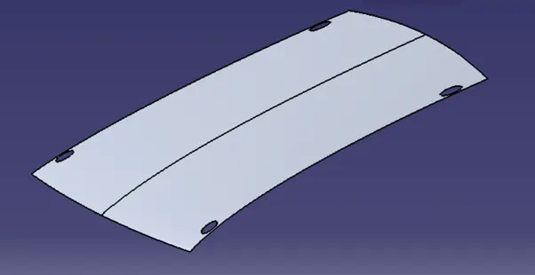
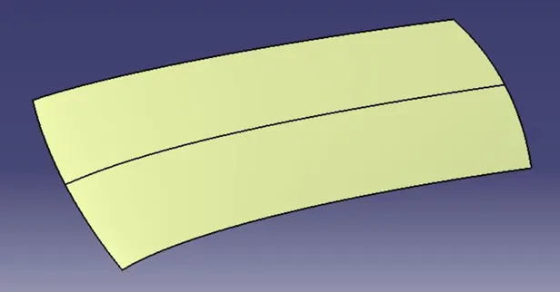
DESIGN CONSIDERATIONS
ROOF DITCH AREA
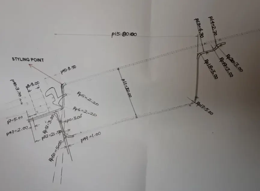
The Roof area is developed based on the Master Section and provided with Positive Draft Angle for all the flanges to have a feasible manufacturing.
The Opening angle condition determines the visibility criteria of the passenger hence the flange on frontal Roof area is set to 3 degrees
The Rear Roof Area is designed for Back Door Opening to accommodate backdoor components
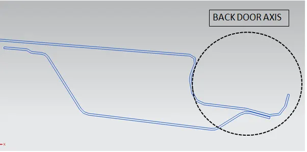
The Tail gate opening Axis is shown above
For Manufacturing Feasibility,
1) Corner Relief are porvide along the bend corners to avoid stress concentration and better Tool Path
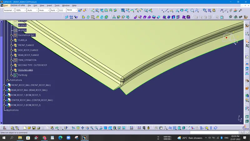
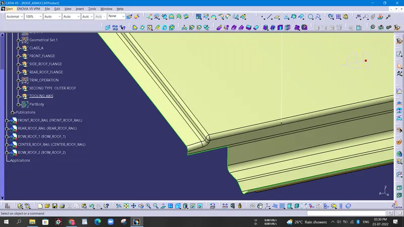
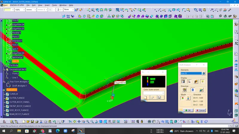
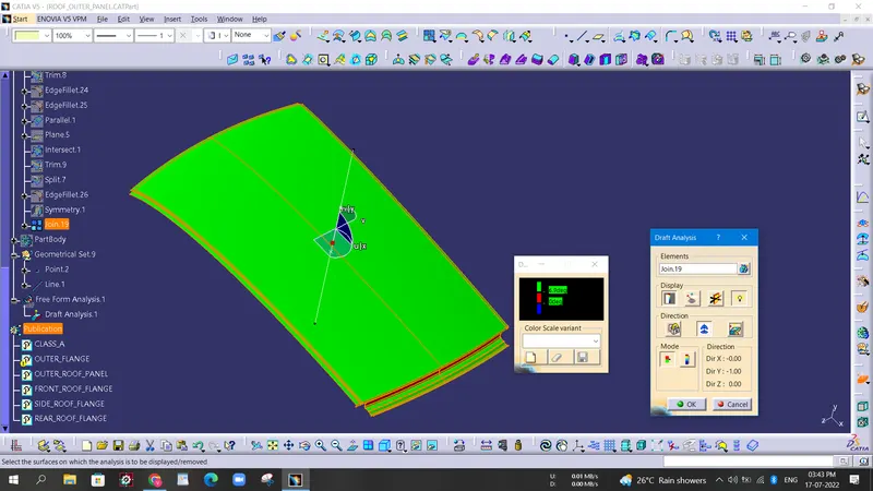
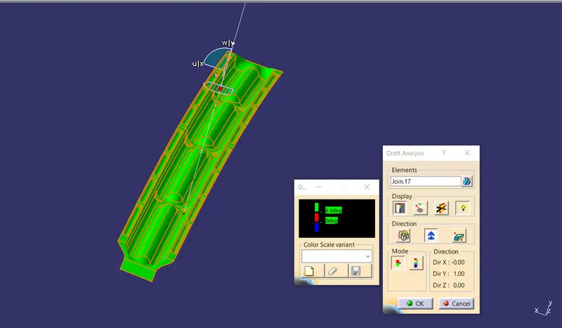
2) Draft Analysis is done to avoid Negative Draft which adds complexity to produce parts
Draft Analysis Report For frontal area of Roof is shown below
FRONT RAIL
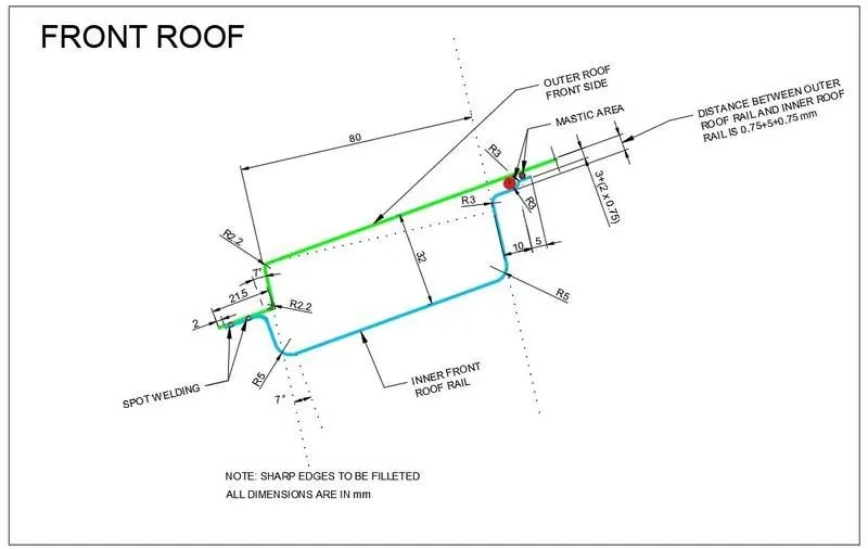
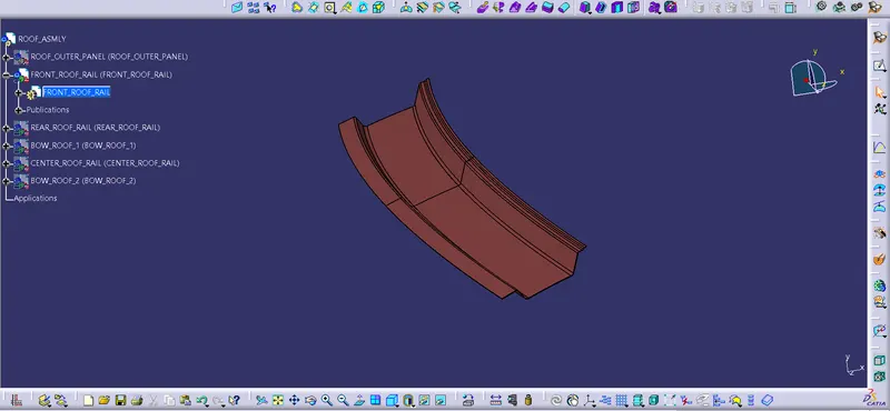
The Front Roof Rail is designed to accommodate Wind Shield Glass with Rubbers Sealant hence a Frontal clearance of minimum 21 is provided.
The Opening angle condition determines the visibility criteria of the passenger and is set to 3 degrees and the depth of the Rail is restricted not beyond 32mm to provide tooling workability consideration and the distance of Front Rail is usually limited to 80mm to provide ample head room clearance.
Based on these considerations the Flanges are worked around with a thickness of 0.75mm.
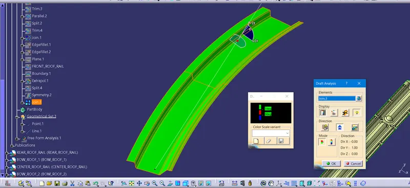
Positive Draft Angle condition is maintained for all the law extensions and Draft Analysis is done to ensure the above condition
Draft Analysis Report For Front Roof Rail is shown below
The Master Section and Section modulus report for Frontal Rail are given below
REAR ROOF RAIL
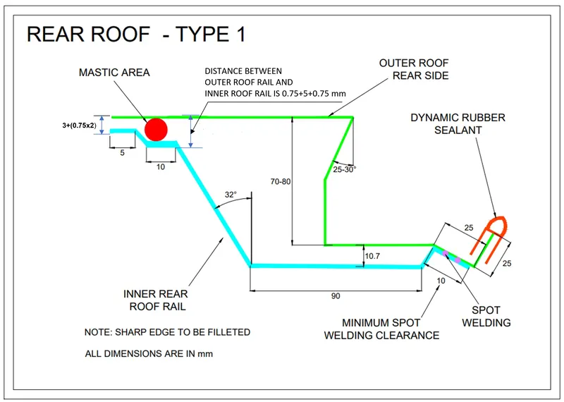
The Rear Roof Rail is designed and positioned based on the Roof Area and the thickness of the part is 0.75mm and has a close tolerance at the start and end of the part to achieve the fixation of Roof Rail to the Roof Area
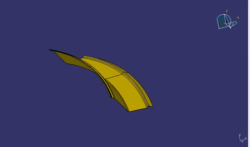
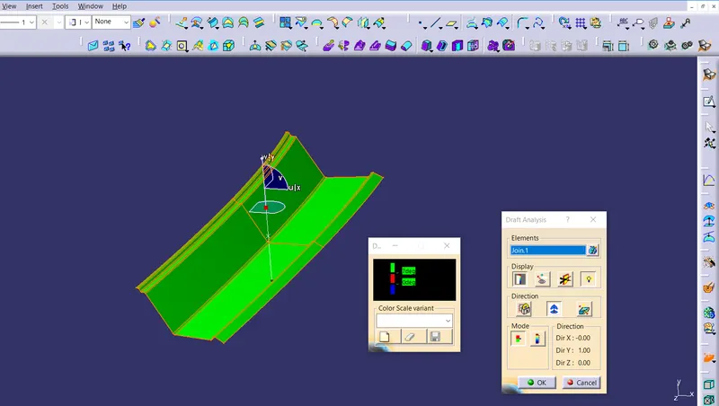
The Master Section data and Draft Analysis Report are attached below
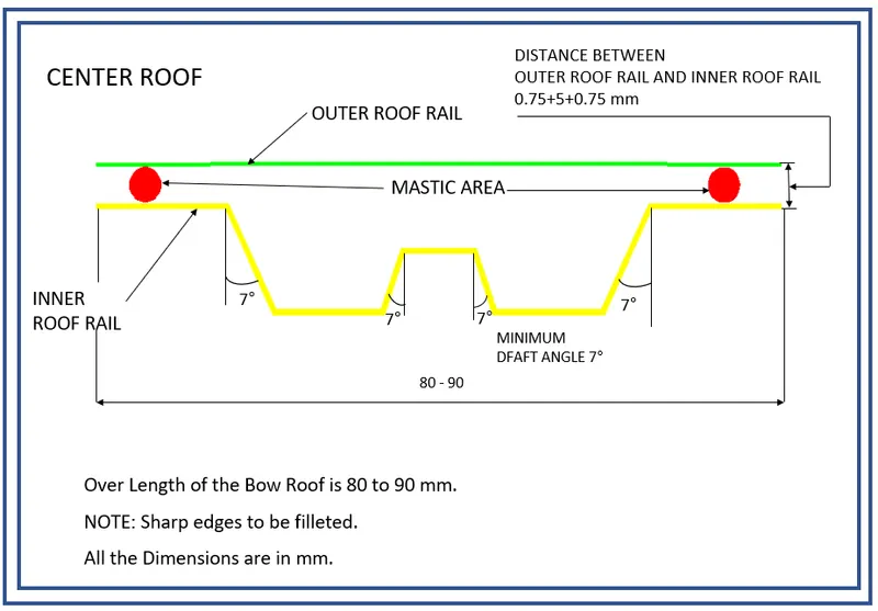
CENTER ROOF
The model has Center Rail Reinforcement that provides strength to the Roof and the also houses other mounting features. This model has Center Roof reinforcement along with the bow roof.
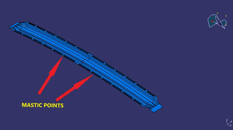
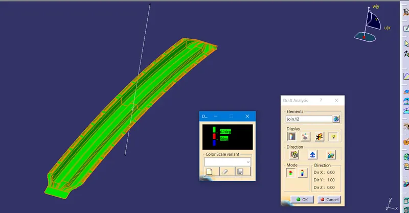
The Position of the reinforcements are based on the Roof Curvature study. The Structure is mounted with a spot weld and hence has very tight tolerance with the roof. Master Section and Draft analysis report are attached below
BOW ROOF
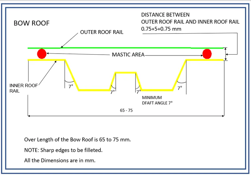
The Model has two Bow Roof one between the Front Rail and Center Roof Rail and other between the Center Roof Rail and Rear Roof Rail respectively.
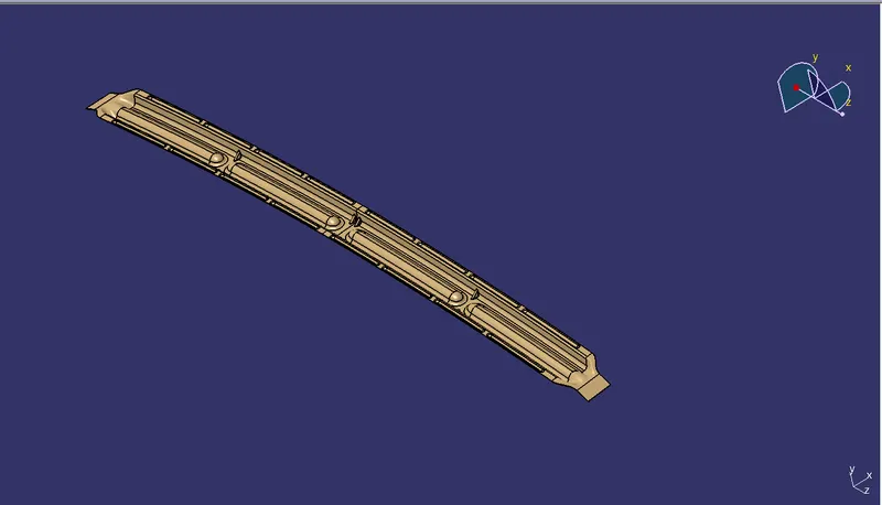
The Bow Roof is provided to withstand the load conditions under different situations. The Bow roof is mounted with Mastic Sealants and the mastic Influence increases the strength of the component.
ANALYSIS
After the assembly, we do a curvature on the roof to justify the position of bow roofs. For that, we normally test 3 criteria.
- Roof Crush Test
- Heat Distortion
- Snow Load
Roof Crush Test
This test is done after manufacturing the roof with complete assembly.
Heat Distortion
This test is done to know at which temperature the material deforms under a specific load. These test results show the withstand capability of the roof and the bow roofs which was assembled.
W = [1.73 x 10^(-3) x L] + [1.85 x 10^(-8) x (R^2)/t] + [ 1.10x10^(-3) x l] - 2.68
Judgement Condition : OK< 2.7> 3.1
Where
L = Roof Length in X-Direction[mm](Roof dimension in 0-Y)
R = Roof curvature
R = 2(Rx*Ry)/(Rx+Ry)
Rx = X curvature
Ry = Y curvature
t = Roof plate thickness [mm]
l = Bow Roof Span [mm]
Except Rx and Ry all values can be measured on the model.
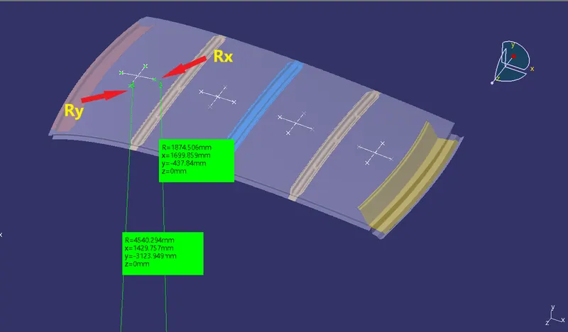
To get the Rx and Ry curvature a sketch was required-
- A sketch was created on a plane on top of the Roof
- 0-Y line was created in the X-Direction in center of roof
- Then a Horizontal line below 300mm was created named as -3Y Line
- Two lines on both sides at 100mm were created from -3Y Line
- Intersection point on line was created and projected on outer Panel of Roof
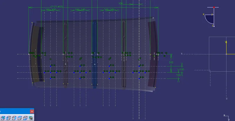
Projected Points
Then Three point Arc was created by using these points
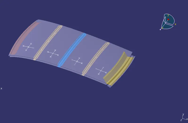
Then Minimun Radius of curvature was measured to get the Rx and Ry Value
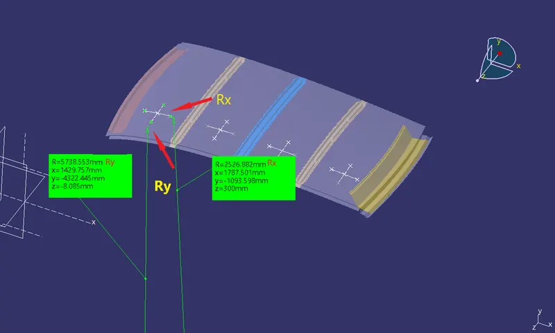
By using all Values Heat Distortion was Calculated in the MS Excel
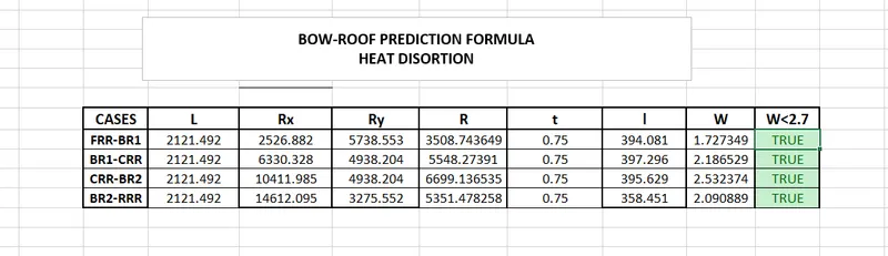
Judgement Condition : OK< 2.7> 3.1
All Values are under Judgement Condition.
Snow Load Calculation
During Winter Season the snow gets clogged over the top surface/roof of the car and the snow has some mass on it. Due to this, the roof can fail if the snow load exceeds the capacity of the roof that was designed to sustain.
Snow load Prediction formula
Qr = [Iy x t2] / [α x s x [(Rx + Ry)/2]2 x 10-8]
Where
α = My x Lx2 x 10-12 , My = Y(Ly-Y)
Judgement condition = Qr ≥ 3.1
250 ≤ s ≤ 380
t = Roof plate thickness [mm]
Ly = Distance between the front and rear roof Rails on the Vehicle along with 0Y[mm]
Length of Roof panel with the center point between Roof rail Front /Rear as the front and rear reference point.
Lx = Distance between the Left and Right end of the roof on the Roof BOW [mm]
Width of the roof panel exposed on the surface.
Y = Distance front Front Roof Rail to Roof BOW[mm]
s = Distance for which Roof BOW bears divided load [mm]
s = L1/2 + L2/2
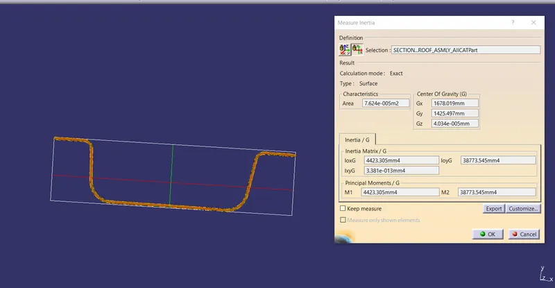
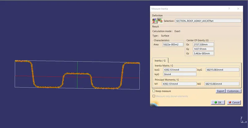
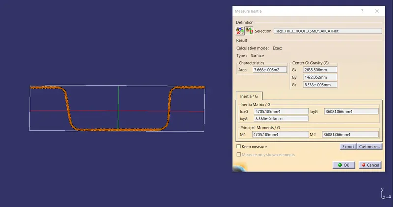
Iy = Geometrical moment of inertia of Roof BOW (Y cross-section )[mm4]
Rx = Lateral direction curvature radius of roof panel Y cross-section on Roof BOW [mm]
Roof panel curvature Radius of the Length Lx in Front view
Ry = Longitudinal Direction curvature radius of the Roof panel X cross-section on Roof BOW [mm]
Roof panel X curvature radius of length s in Side view
To get the values a sketch was created on top of Roof
- O-Y line was created in the center of roof
- A line between First and center Roof rail was created
- Then two lines on both sides at 100mm was created
- Similar lines were created between other center roof rail, both Bow Roof rails and rear roof rails
- Intersection points were created and projected on the roof
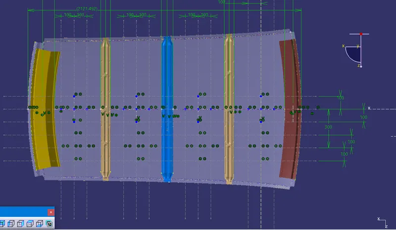
Projected points for Snow load Calculation
Then Three point Arc was created by using these points
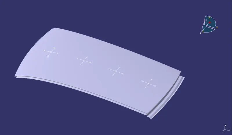
Then Minimun Radius of curvature was measured to get the Rx and Ry Value
Geometrical moment of inertia of Roof BOW
bow roof rail 1
center roof rail
bow roof rail 2
By using all the values Snow load was calculated in the MS Excel
Snow Load Calculation
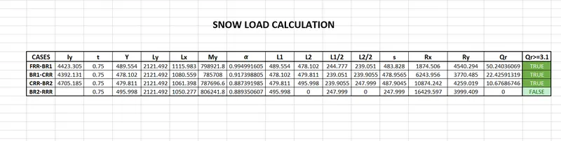
So, according to the Judgement condition = Qr ≥ 3.1
And, Here one result of Qr is not fulfilling the demand. So, there are some solutions, that the model can pass over to the styling team to change the curvature to improve the strength, Bow Roof rails position can be changed to the weaker side of roof or Embosses could be created on the outer panel to improve the strength.
After Completing the Design there are physical test of vehicle is done to check the strength of the Roof with vehicle.
There are various Car Roof Designs to check their strength some tests are done which are:
- Car Roll-over Test - The Roll-over test is conducted because a rollover is a type of vehicle crash in which a vehicle tips over onto its side or roof. Rollovers have a higher fatality rate than other types of vehicle collisions.
Vehicle rollovers are divided into two categories: tripped and untripped. Tripped rollovers are caused by forces from an external object, such as a curb or a collision with another vehicle. Untripped crashes are the result of steering input, speed, and friction with the ground.
The vehicles which have a higher center of gravity like SUV or Small Trucks are more prone to Roll-over. Rollover accidents typically involve a singular vehicle that loses control due to icy or snowy road conditions, soft road shoulders, uneven ground, collision with curbs or guardrails after a vehicle has lost traction, or hitting an obstacle while driving.
During a rollover accident the regional body distribution of injuries normally effects five main areas: head and neck, thorax, abdomen, upper limbs, and lower limbs. The majority of rollover crash victims sustain multiple injuries throughout these regions with the head and neck being the most vulnerable area. Some of the most common rollover injuries include: traumatic brain injury, spinal cord injury, broken bones, and cuts, scrapes, and bruises. These injuries are caused from slamming into another vehicle or obstacle, impact with unsecured cargo, contact with broken glass or torn metal, or from being tossed within the vehicle or ejected from the vehicle.
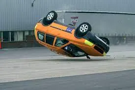
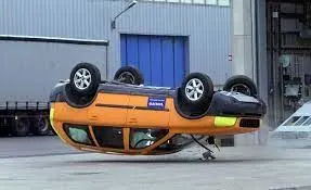
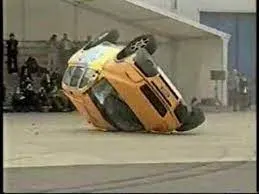
Volvo Roll-Over Test
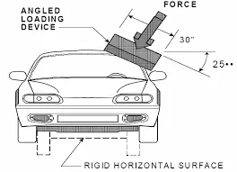
- Roof Crush Test - In this test the load is applied on the roof to test the strength in static car postion. The standard does not apply to school buses and passenger cars that conform to the dynamic rollover test requirements of FMVSS 208, Occupant Crash Protection, and S5.3 by means that require no action by passenger car occupants. It also does not apply to convertibles, except for optional compliance with the standard as an alternative to the rollover test requirements in S5.3 of FMVSS. In April 1991, the National Highway Traffic Safety Administration (NHTSA) announced that FMVSS 216 was to be extended to light trucks, buses and multi-passenger vehicles not exceeding 6000 pounds, and that requirement came into force in September 1993. American statistics have long indicated that the fatality rate when light trucks (including four-wheel drives and utility vehicles) are involved in rollover accidents is twice that for passenger cars.
FMVSS 216 Roof Crush
The purpose of the FMVSS 216(Federal motor vehicle safety standard) is to reduce the head injuries, neck injuries and deaths by the roof crush of the car in to the passenger compartment in rollover crashes.
The resistance of the vehicle roof to deformation is dictated by a static test, in which the force of 1.5 times the unloaded vehicle weight or 5000 pounds, which is less, is progressively applied to the roof of the vehicle in the region of the “A” pillar. Force is applied to the plate at a roll angle of 25 degree and a pitch angle of 5 degree to the direction of the forces simulation can be experienced in rollover crashes. At the t time of the test, displacement of vehicle roof should not more than 5 inches of intrusion, as estimated by the movement of the test device.
Conclusion
The Roof was created in Catia V5 with all the required parameters and different Calculations were done for safety concerns.