Roof challenge
Introduction
The roof panel covers the cab of your truck, and you likely don’t give it much thought most days. Because it is often out of site, you may not notice rust or other damage to this panel. Even direct sunlight over prolonged periods can damage your roof panel.
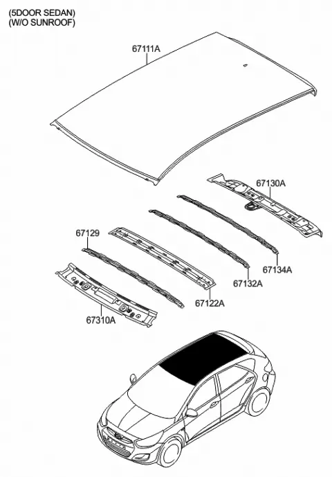
Parts of Roof are
- Front Roof Rail
- Bow roof 1
- Center roof rail
- Bow roof 2
- Rear roof rail
- Front Roof Rail
It is the support that will join the windshield, side body. It will be having a thickness of about 0.75mm and with a draft angle of 3-5 degrees which is provided for stamping operation.head room clearance and the driver visibility are the two important factors to be considered for front roof rail design.
Design of ditch area of front roof rail
Flange of 15mm created with the law extension, with the proper angles and length mentioned in the master section. This will affect the visibility and head room clearance
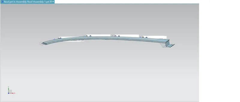
2. Bow Roof
It will form the support for the roof which will provide support for the outer panel and also provides the load carrying capacity. There will be at least 2 roofs present for a less length of car and it may be more than 2 if the length of the car is more. In this design we have designed 2 bow roofs. Which will be placed at the front end and also at the rear end before front and rear roof rails respectively.
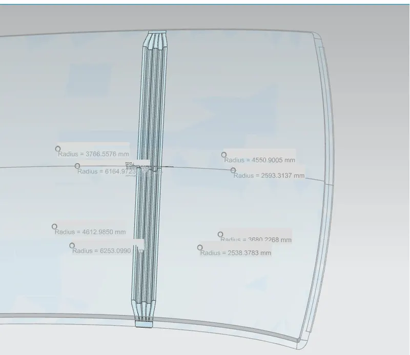
3.Center roof rail
It may also be called a reinforcement center which is used as a cross member between body sides . In some cases center roof rail is not joined with the roof , it is made to join in both roof and bodyside.
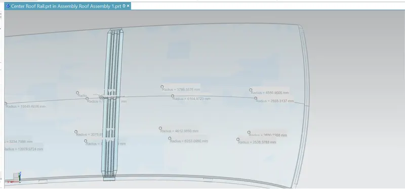
Rear roof rail and ditch area
It will have a ditch area to support the backdoor . The ditch area will be the extended flange, which will be modeled in NX by using law extension with appropriate angles and lengths according to the master section .
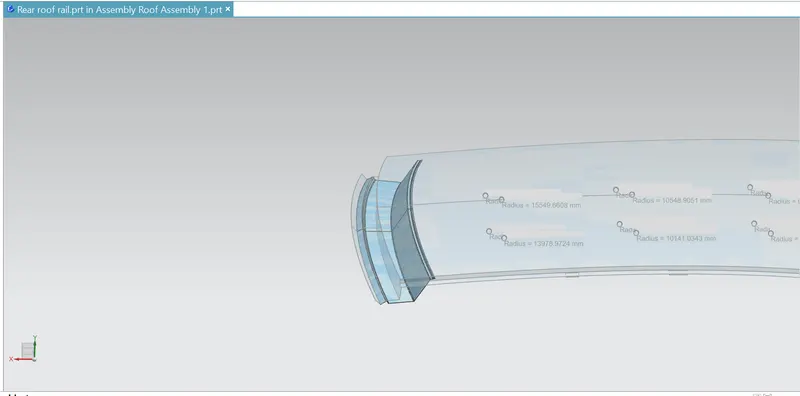
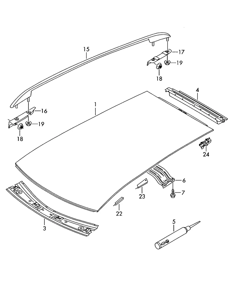
Factors to be considered for designing Roof
1. Visibility criteria
2. Head clearance for comfort
3. Draft analysis
4. Section modulus analysis
5. Heat distortion criteria calculations
6. Snow load criteria calculations
Draft analysis
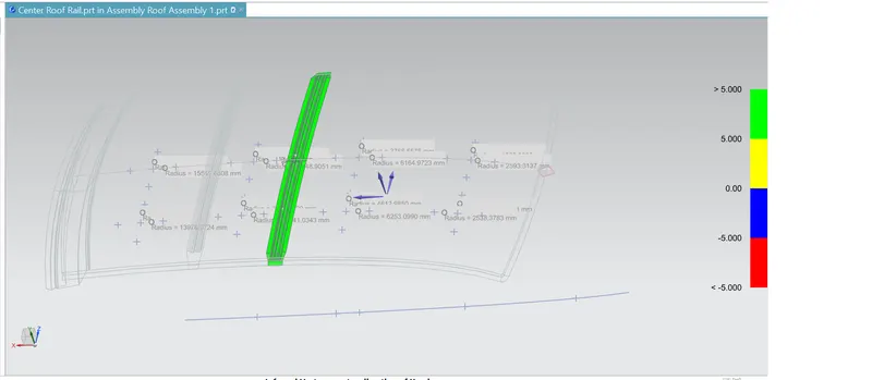
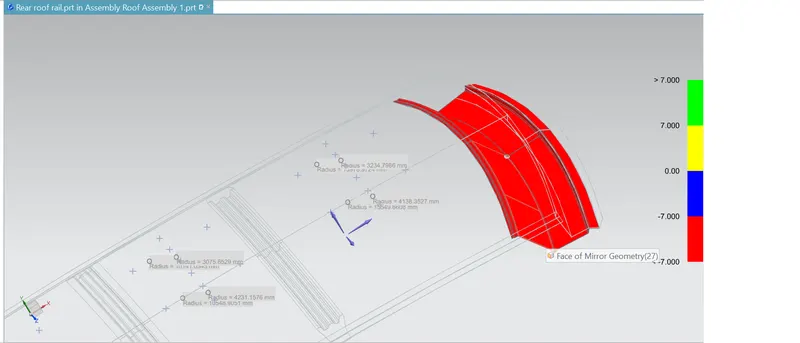
The main aim of draft analysis is to check the draft angle provided in the component is up to the mark. For easy manufacturing there should be a minimum draft angle should be 7 degrees . This can be measured in NX cad by using option draft analysis which will show the regions in different colors which will indicate angles .
Images of Draft Analysis
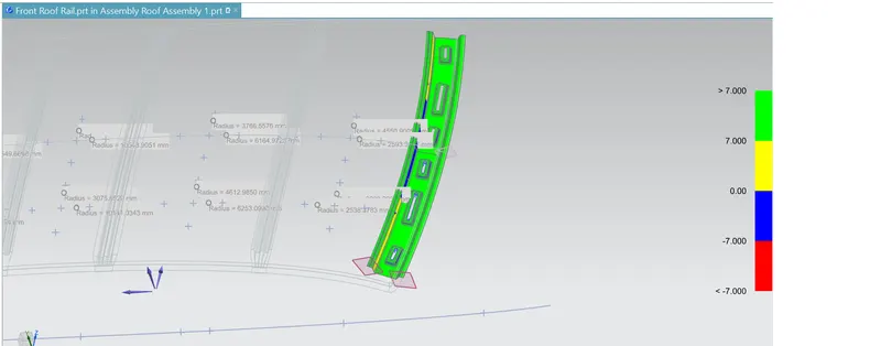
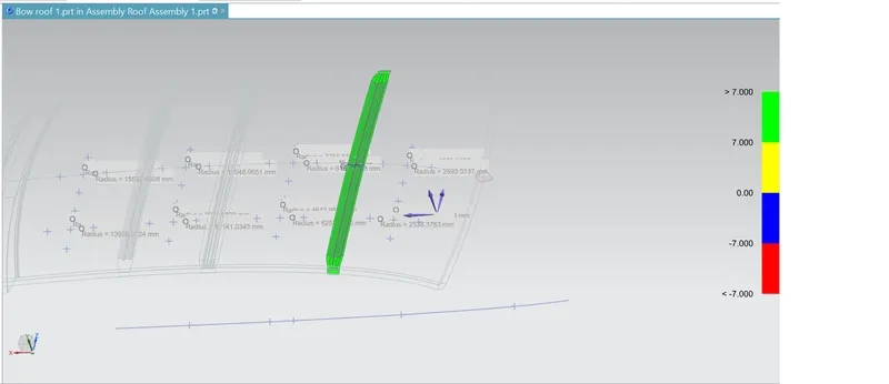
Section Modulus
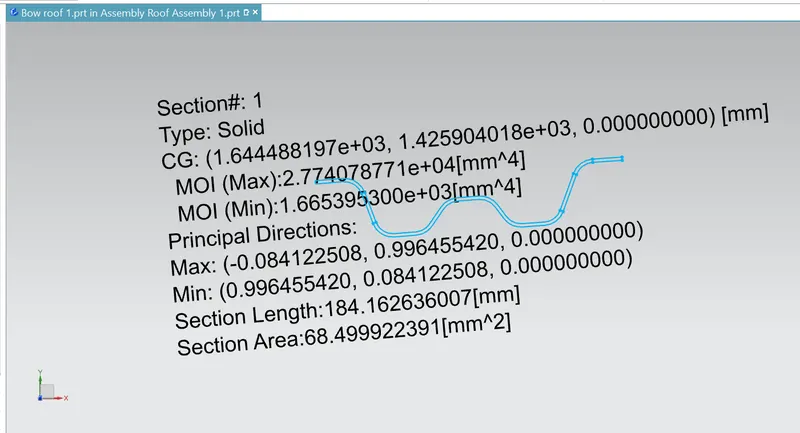
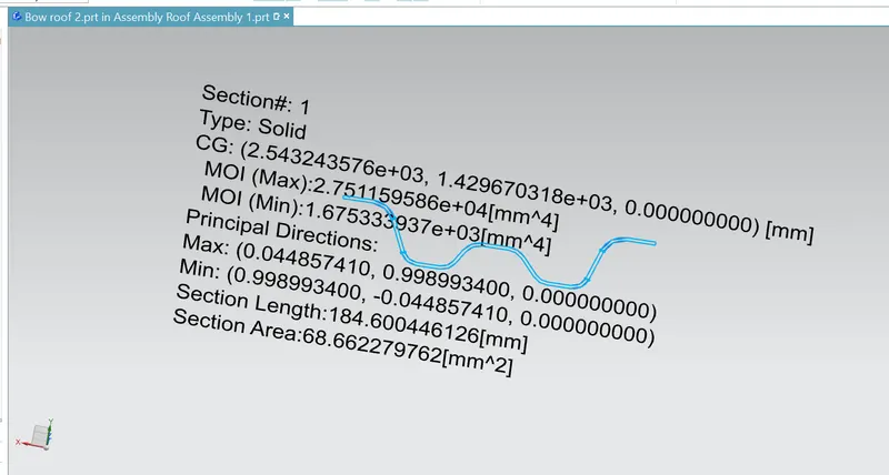
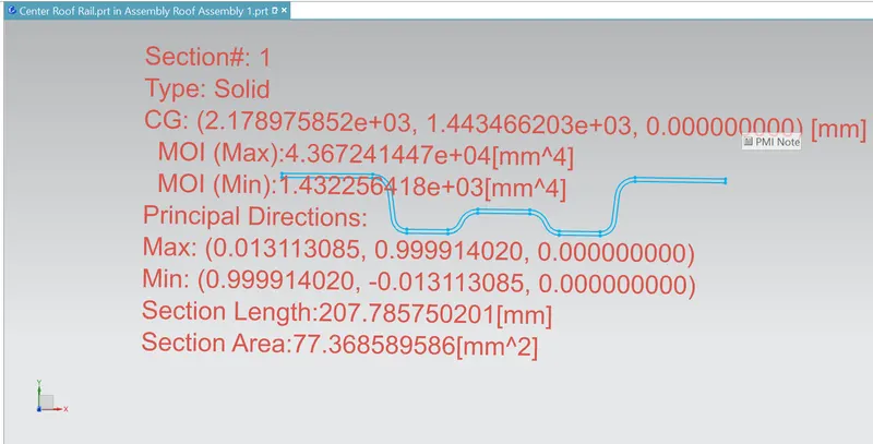
The strength of the section can be measured by the section modulus which will play an important role
for designing. The value of the section modulus should be more to obtain more strength which in turns supports the more load
Section modulus= Z=I/Y
Where
I = Moment of inertia(mm^4)
Y= distance between the NA and the Extreme end of the object(mm)
Heat criteria calculations
Bow–Roof Prediction Formula
W = [1.73 x 10^(-3) x L] + [1.85 x 10^(-8) x (R^2)/t] + [ 1.10x10^(-3) x l] - 2.68
Where,
L = Roof Length in X-Direction[mm](Roof dimension in 0-Y)
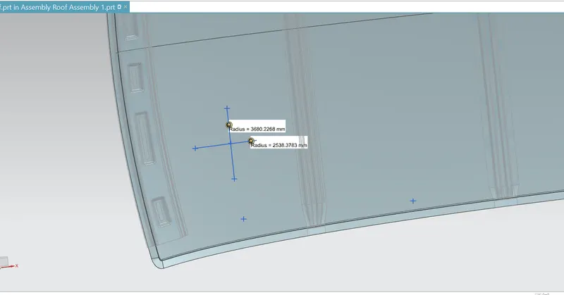
R = Roof curvature
R = 2(Rx*Ry)/(Rx+Ry)
Rx = X curvature
Ry = Y curvature
t = Roof plate thickness [mm]
l = Bow Roof Span [mm]
Procedure to measure the parameters
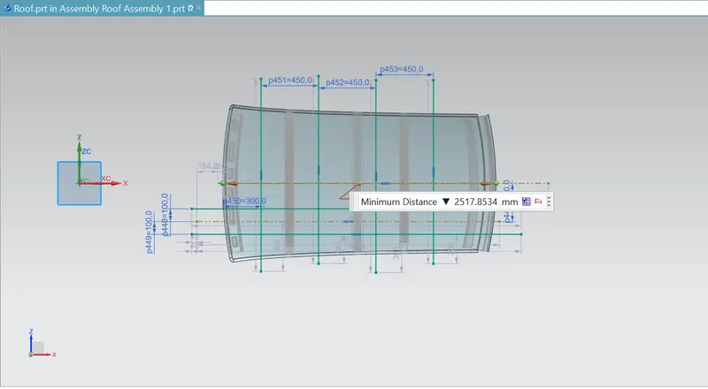
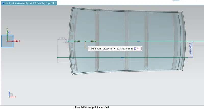
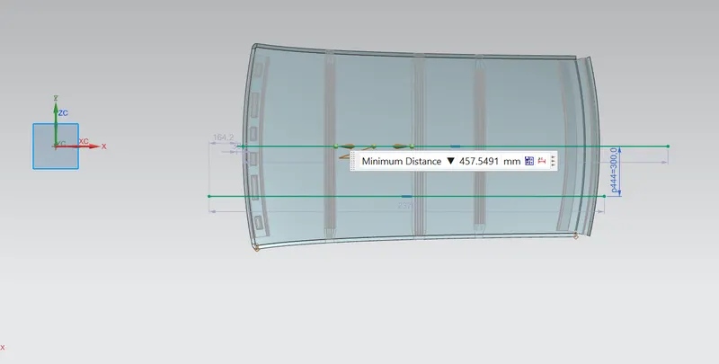
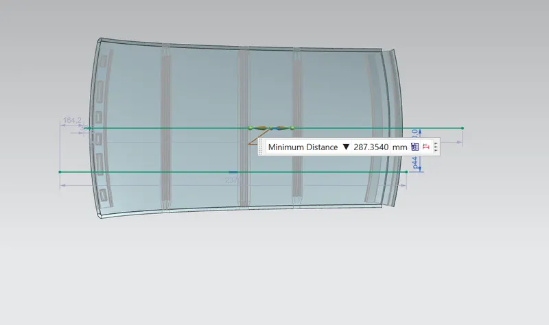
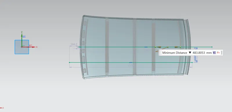
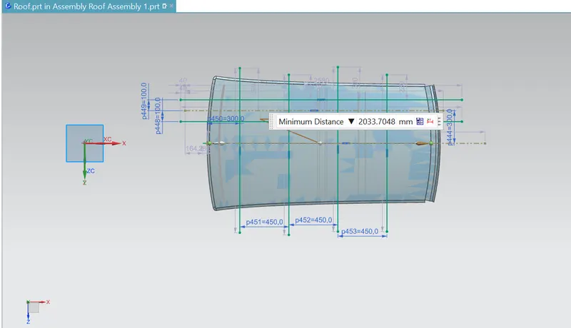
- On the plane parallel to the top draw a center linje and name it as OY
- Then offset the OY line 300mm towards down side
- Offset the bottom line 100mm on either side of the 300mm line
- Mark the points at the edges of front roof rail, bow roof, center roof, rear roof rails
- Mark intersection points on the 100mm reference lines and project it on the surface of the panel
- Draw the 3 point arc and measure the radius for obtaining the Rx, Ry values

Judgment Condition
OK< 2.7
Snow Load Prediction Formula
Qr = [Iy x t2] / [α x s x [(Rx + Ry)/2]2 x 10-8]
Note: The Qr value given over here is correct. There was a typo error in the formula given in the video.
Where,
α = My x Lx2 x 10-12 , My = Y(Ly-Y)
t = Roof plate thickness [mm]
Ly = Distance between the front and rear roof Rails on the Vehicle along with 0Y[mm]
Length of Roof panel with the center point between Roof rail Front /Rear as the front and rear reference point.
Lx = Distance between the Left and Right end of the roof on the Roof BOW [mm]
The width of the roof panel is exposed on the surface.
Y = Distance front Front Roof Rail to Roof BOW[mm]
s = Distance for which Roof BOW bears divided load [mm]
s = L1/2 + L2/2
Iy = Geometrical moment of inertia of Roof BOW (Y cross-section )[mm4]
Rx = Lateral direction curvature radius of roof panel Y cross-section on Roof BOW [mm]
Roof panel curvature Radius of the Length Lx in Front view
Ry = Longitudinal Direction curvature radius of the Roof panel X cross-section on Roof BOW [mm]
Roof panel X curvature radius of length s in Side view

Judgment Condition
Qr > 3.1
Manufacturing equipment
Punch & Die
Punch and die is a combination which is used to perform various operations in sheet metal like Punching, Blanking, Notching, Slitting, Piercing, etc. in general mechanism in punch and die operation is the Punch being forced down causing an initial deformation of the material to be cut. Penetration The Punch is forced deeper into the material which starts to penetrate the Die below. Fracture: the material fractures under the force of the punch as compared to a cutting action of a drill or saw.
There are various types of punch and dies types are available like
Simple Dies : Also known as a single operation die, the simple die is a shaping tool that performs one operation per press slide stroke. This type of die is typically used for smaller applications in the workplace. For example, it may be useful for the manufacturing of simple metal parts
Compound Die : For more demanding or complex blanking and piercing applications, a compound die can do the job faster. Rather than handling just one operation at a time, the compound die can simultaneously complete the blanking and piercing processes. The compound die is less useful for bending and forming operations, and it tends require a higher level of force than some of the other options
Progressive Die : While a progressive die can handle more than one operation at a time, it does so in several stages throughout multiple workstations. The progressive die’s main advantage is that it’s more efficient thanks to its high work speed and the reduced level of force.
Combination Die : The combination die is similar to the compound die in terms of design and efficiency. It can handle more than one operation at once, which allows it to deliver faster, more reliable results. As an added bonus, the combination die is well-suited for both cutting and shaping applications.
Operations in Sheet Metal
Stamping (also known as pressing) is the process of placing flat sheet metal in either blank or coil form into a stamping press where a tool and die surface forms the metal into a net shape. Stamping includes a variety of sheet-metal forming manufacturing processes, such as punching using a machine press or stamping press, blanking, embossing, bending, flanging, and coining. This could be a single stage operation where every stroke of the press produces the desired form on the sheet metal part, or could occur through a series of stages. The process is usually carried out on sheet metal, but can also be used on other materials, such as polystyrene. Progressive dies are commonly fed from a coil of steel, coil reel for unwinding of coil to a straightener to level the coil and then into a feeder which advances the material into the press and die at a predetermined feed length. Depending on part complexity, the number of stations in the die can be determined.
- Bending - the material is deformed or bent along a straight line.
- Flanging - the material is bent along a curved line.
- Embossing - the material is stretched into a shallow depression. Used primarily for adding decorative patterns.
- Blanking - a piece is cut out of a sheet of the material, usually to make a blank for further processing.
- Coining - a pattern is compressed or squeezed into the material. Traditionally used to make coins.
- Drawing - the surface area of a blank is stretched into an alternate shape via controlled material flow.
- Stretching - the surface area of a blank is increased by tension, with no inward movement of the blank edge. Often used to make smooth auto body parts.
- Ironing - the material is squeezed and reduced in thickness along a vertical wall. Used for beverage cans and ammunition cartridge cases.
- Reducing/Necking - used to gradually reduce the diameter of the open end of a vessel or tube.
- Curling - deforming material into a tubular profile. Door hinges are a common example.
- Hemming - folding an edge over onto itself to add thickness. The edges of automobile doors are usually hemmed.
Piercing and cutting can also be performed in stamping presses. Progressive stamping is a combination of the above methods done with a set of dies in a row through which a strip of the material passes one step at a time.