Roof challenge
ROOF DESIGN CHALLENGE
Our next task after the section modulus challenge is the roof design challenge. The roof is basically one of the important part of the automotive, as it protects the user from the different weather conditions. Here we are given the Class A Surface of the roof as shown in the figure below. And our task is to convert the roof into the fully developed solid model using the masters section provided to us as an input as shown in the figure below.
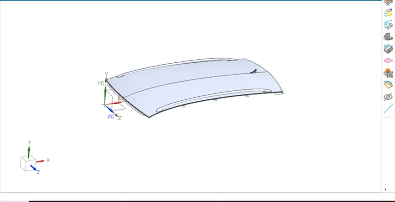
ROOF CLASS A SURFACE
MASTER SECTION PROVIDED :-
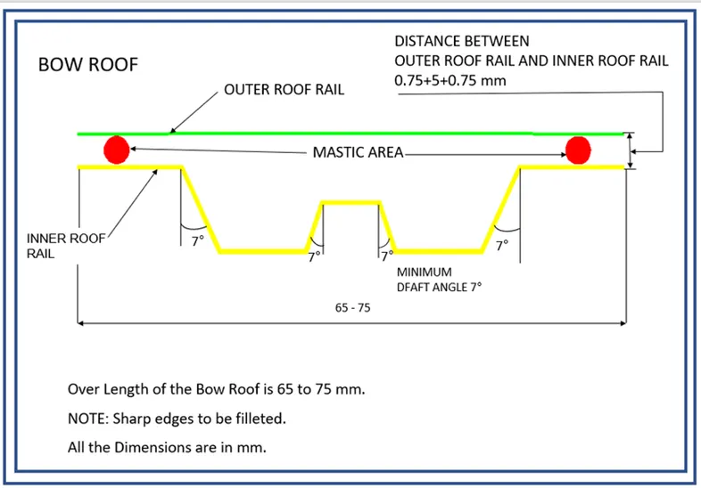
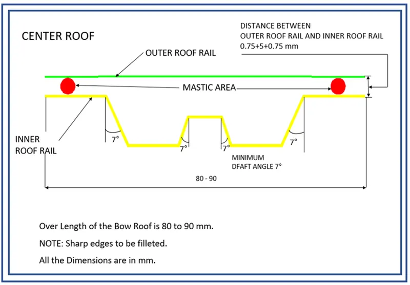
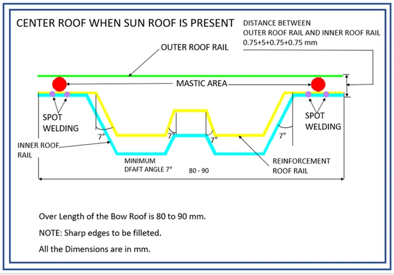
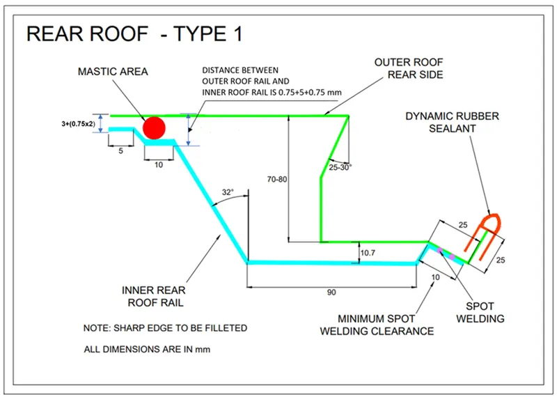
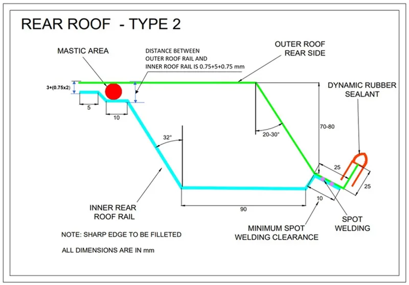
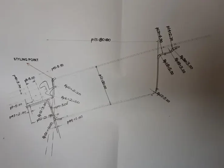
Well all the images that we saw just above are the master section provided to us in order to design the roof. So now all the necessary data that is required to design the roof is available. Lets start the design.
Initially we got to understand what actually the master section is going to convey us. Here as we see the image given below what actually is the data given to us.
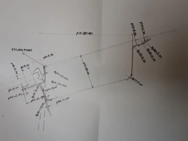
Here we can see initially we are given the styling point from where we need to start the design of the roof. Now according to the master section the upper roof is designed using the law extension command as shown in the figure below. Then the face fillet of the 2.2mm is provided to avoid the sharp edges.
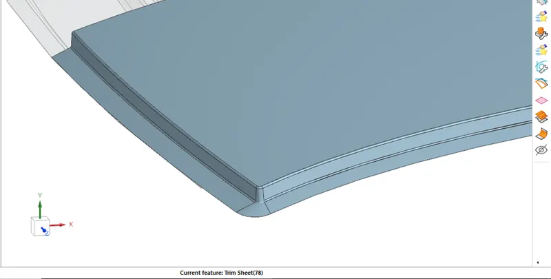
In the sheet metal design we need the draft angle minimum of 7 degree in order to clear the tooling and make the part manufacture-able. Here the front ditch area is designed.
Now as we take the close look to the rear part i.e the upper rear master section we get to know that the values are provided to us as shown in the figure below.
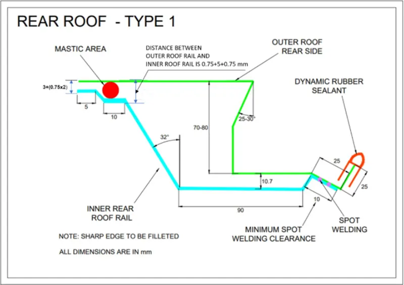
The green coloured highlighted area is the roof rear area that is to be designed using the law extension commands. Here the surfaces are developed according to the given values and at certain angle and then finally the fillets are provided as shown in the figure below.
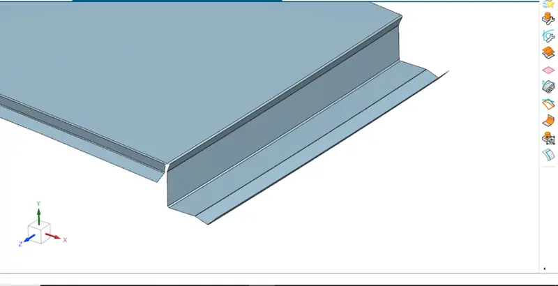
Here we can see the roof rear master section is fully designed.
Now actually the whole roof is mirrored to the other side in order to create the full roof design and are sewed together as shown in the figure below.
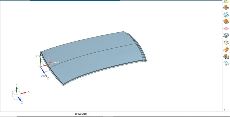
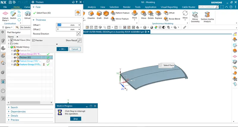
Now the upper styling of the roof is fully designed. The thickness of 0.75 mm is provided to the roof as shown in the figure below.
Now the next master section provided is of the front roof rail as shown in the figure below.
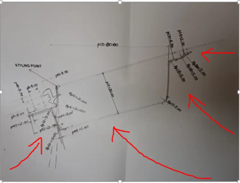
What is roof rail? Actually the roof rail is the structure that is provided under the main roof in order to provide the strength and stiffness to the roof. In simple language it helps the roof from getting bend, due the load applied externally.
Now as we can see the red colour highlighted area is the front roof rail master section that we need to design. All the parts are created as an individual part file as we need to assemble them at last.
Now the values of the front roof rail are taken into consideration and is designed accordingly using the law extension command and the face fillet option as shown in the figure below.
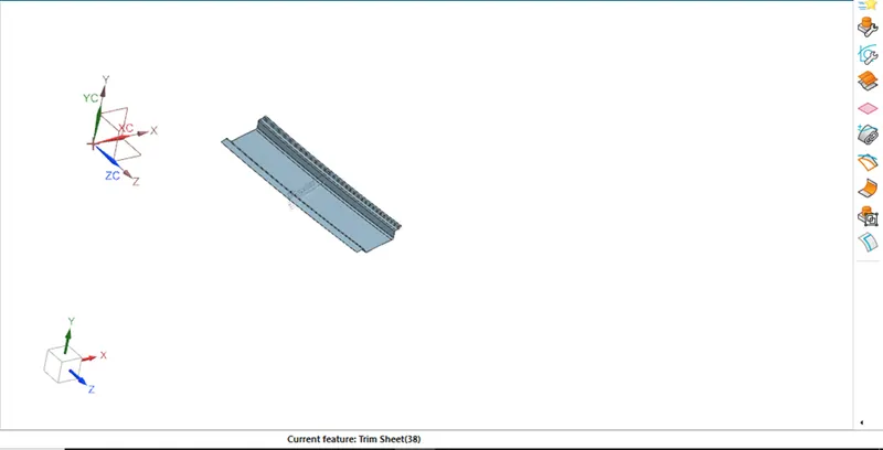
The design of the front roof rail is completed, now this geometry is completely mirrored to the other side and the surfaces are sewed. Finally the thickness of 0.75mm is provided to the front roof rail as shown in the figure below.
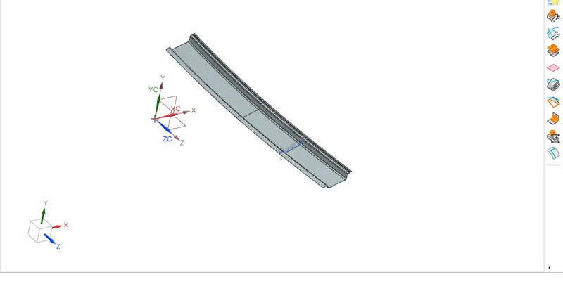
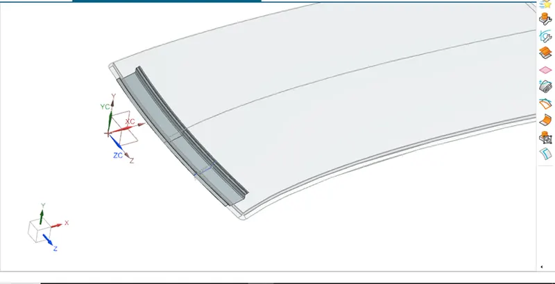
The design of the front roof rail is fully completed.
Similarly now we got the next master section of the rear roof rail as shown in the figure below.
Now the one in the blue colour highlighted structure, is the master section that is to be designed.
The rear roof rail is designed in the same way as it was designed for the front roof rail. The law extension command is used to create the surface at an angle.
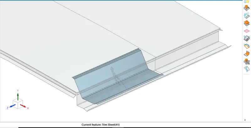
The rear roof rail is designed, now the whole geometry is mirrored to the other side and the thickness of 0.75mm is provided to the rear roof rail as shown in the figure below.
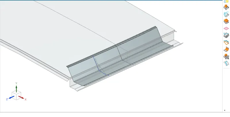
Now our roof, front roof rail and rear roof rail is designed fully.
Now here comes the quite harder task we need to design the bow roof including the reinforcement centre roof in order to provide the strength to the roof.
Here there is not any hard and fast rule to calculate the no of the bow roofs. But here in this roof design we are not designing the sun roof so here the minimum bow roof design are 4 i.e 3 bow roof and 1 reinforcement bow roof. Here one additional reinforcement bow roof is added in order to provide the additional strength to the roof.
Now to locate the bow roof one by one, here the offset in face command is used, planes are located and the intersection is created with the roof styling surface to get bow roof location as shown in the figure below.
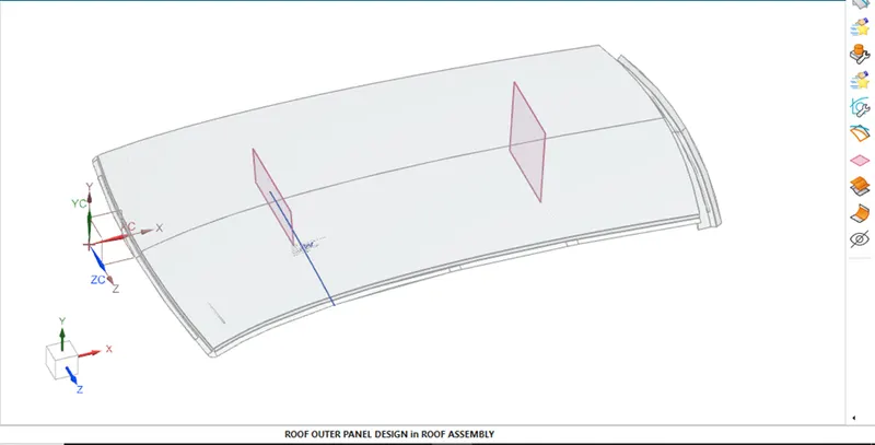
In the above figure we can see we have marked the position of the bow roof, our next task is to design the bow roof one by one in order to provide the strength to the main roof.
So now the curves are offset one by one at the certain distance as mentioned in the master section given in the figure below.
Now as all the lines are offset we need to offset the surface in order to design the bow. Here as we can see closely, we need the clearance for the upper surface as we are going to attach the bow roof using the mastic sealants so here the upper surface is offset by 0.75mm the thickness of upper panel + 5mm the mastic sealants space + 0.75mm the thickness of bow roof. So here the upper surface is offset. Then the bottom surface is offset at 20mm and the middle one is offset at 6.5+4mm. Then the surfaces are trim according to the curves offset, one by one as shown in the figure below.

Now this surface are joined using the surface studio command and then the fillet of 2.2mm is provided as shown in the figure below.
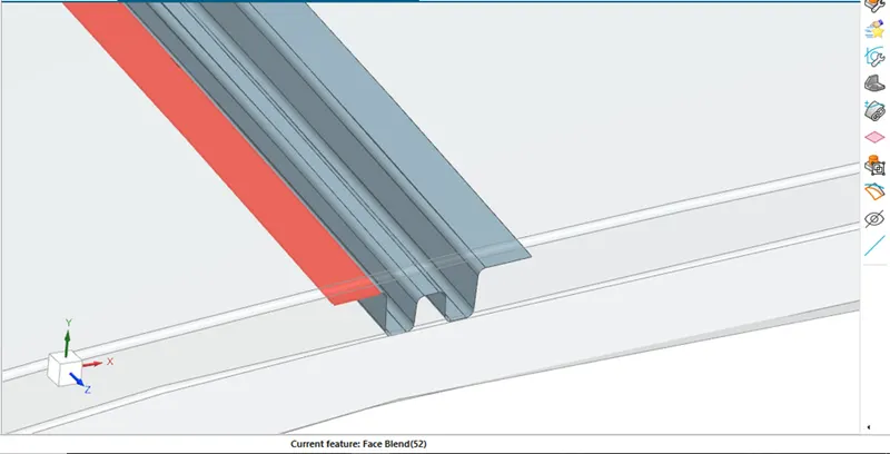
Now here the side attachment surface is designed in order to attach the bow roof to the side flange of roof. And then the mastic mountings are designed on to the upper outer flange of the bow roof as shown in the figure below.
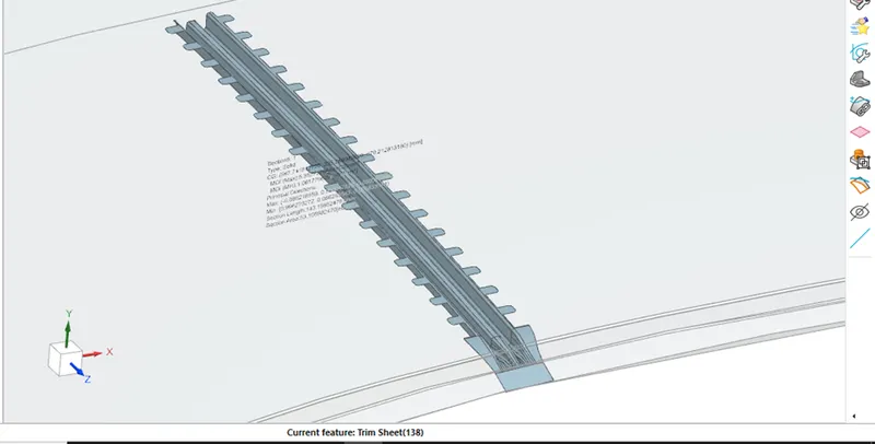
Here our bow roof 1 is designed now this whole geometry is mirrored on to the other side of the component, then the surfaces are sewed and finally the thickness of 0.75mm is provided to the bow roof as shown in the figure below.
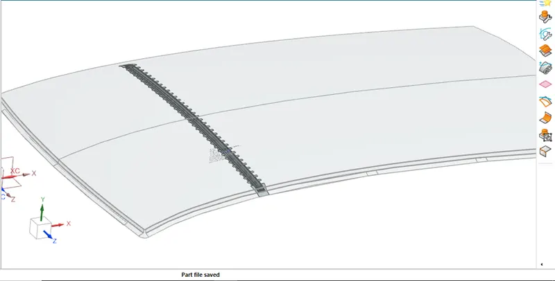
Hence our bow roof 1 is designed.
As we have designed the bow roof 1, this same process is followed in order to create the bow roof 2 and bow roof 3. Here the same values are used to design bow roof 2 and bow roof 3 as shown in the figure below.
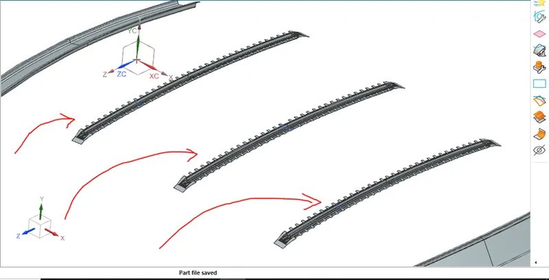
In the above image we can see that all the bow roof are designed.
Now our next task is to design the reinforcement bow roof. The process to design the reinforcement bow roof is same as all the bow roof, but here the difference is of the dimension that are considered while designing. Here the master section is provided to design the centre reinforcement bow roof as shown in the figure below.
Here we will not consider the sun roof simply the reinforcement bow roof is designed considering the given dimensions as shown in the figure below.
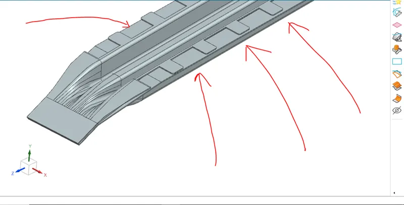
Here our reinforcement bow roof is fully designed. The thickness provided to the bow roof is 0.75mm.
Now we have designed all the necessary part files of roof design.
As we have initially designed the parts individually/separately i.e in different part file. Now we just need to assembly all the parts into the assembly part file as shown in the figure below.
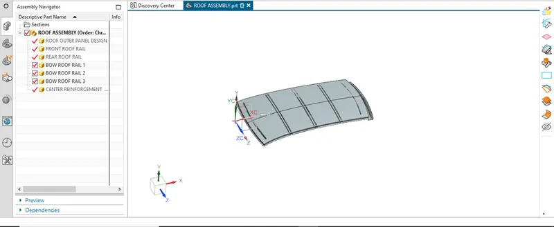
Now here the design of the roof is fully completed.
Now as we have completed the roof design so here we need to do the draft analysis for each of the parts of the roof assembly and to get the conformation that are this part/components are able to manufacture or not.
So let’s start with the roof outer panel
In sheet metal the minimum draft angle is 7 degrees
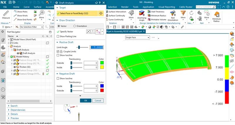
Here the roof outer panel cleared the draft analysis.
The next part is front roof rail.
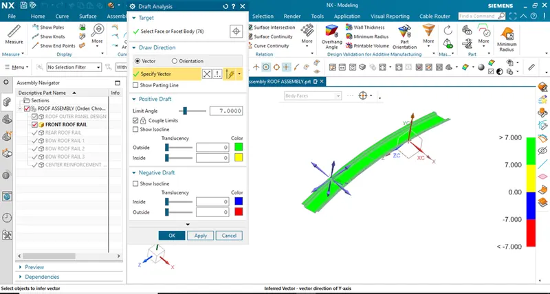
As we can see the front roof rail has cleared the draft analysis.
Now the rear roof rail.
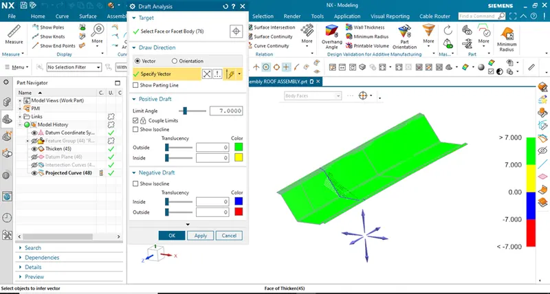
The rear roof rail has cleared the draft analysis.
Now the bow roof rail.
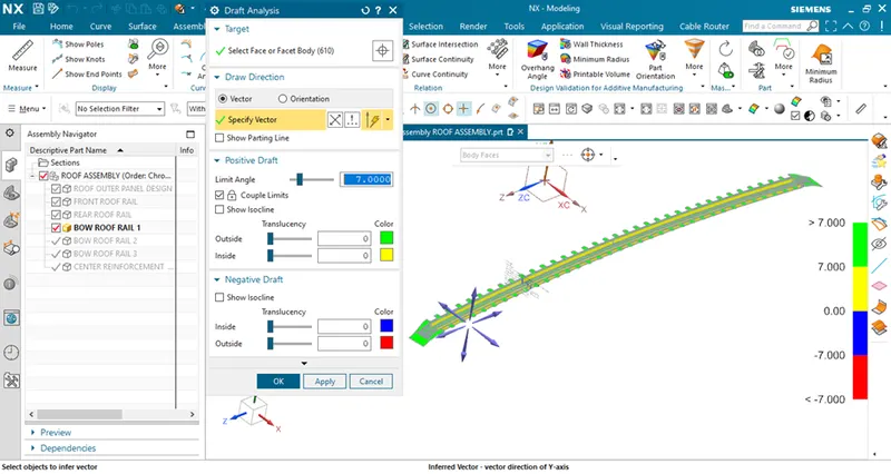
Here we can see that some part is shown in yellow color it means there the angle is less than 7 degree but it is clearing the tooling and not showing the negative draft.
Now the bow roof 2.
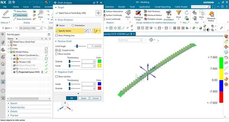
Now the bow roof 3 and the centre roof rail.
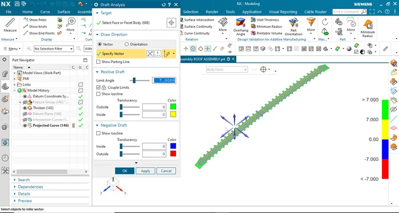
Bow roof 3.
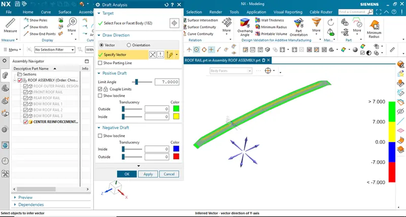
Reinforcement rail roof.
So we can see that all the components are clearing the draft analysis and can be manufactured so now let’s move to the calculation part.
Now as we are all aware of the roof design procedure and its dimensions as well as the design rules that are taken into the considerations while developing the roof design assembly. Here comes our next task i.e the calculation part.
Generally in the roof design 2 types of the conditions are tested they are as follows:-
- Heat distortion condition/criteria
- Snow load condition/criteria
What is heat distortion criteria ad snow load criteria?
- This criteria are nothing but, it is used to check weather roof design can sustain in the different climate condition i.e excessive heat condition and snow load condition. Talking about our region in india this is not that useful but as we design the product so it should design in such a way that it should be a feasible design universally in all climate condition.
So now here initially the heat distortion criteria is calculated and then the snow load criteria is calculated.
HEAT DISTORTION CRITERIA:-
We are provided the formula to calculate the heat distortion criteria. The formula is as follows:-
W = [1.73 x 10^(-3) x L] + [1.85 x 10^(-8) x (R^2)/t] + [ 1.10x10^(-3) x l] - 2.68
The above given formula is the heat distortion criteria formula. Here the value of W should be less then and equal to 2.7 as mentioned.
Now to start the calculation we need to get to know what actually the values we needed with respect to roof.
L = Roof Length in X-Direction[mm](Roof dimension in 0-Y)
R = Roof curvature
R = 2(Rx*Ry)/(Rx+Ry)
Rx = X curvature
Ry = Y curvature
t = Roof plate thickness [mm]
l = Bow Roof Span [mm]
This are all the values that are required to verify the heat criteria.
So here the points and arcs are drawn on y 300 position as shown in the figure below. Then all the distance i.e I, Ry is calculated and are put up into the formula and the following results are drawn:-
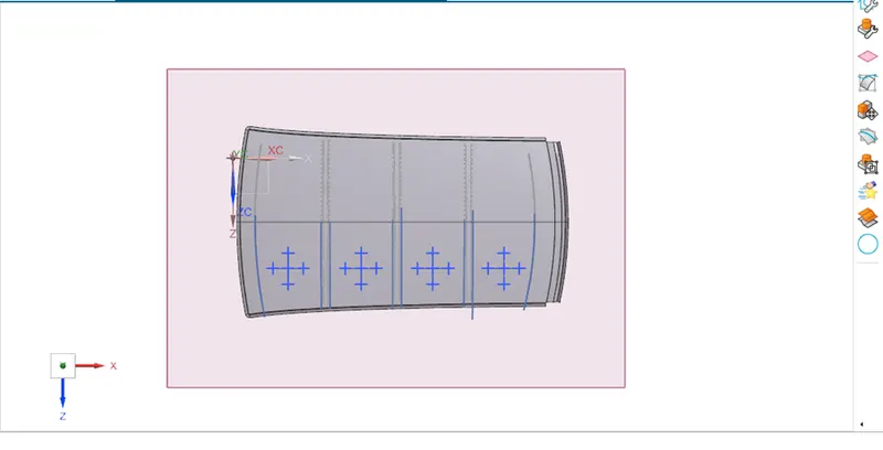
Heat distortion criteria at y -300.
|
Sr no. |
Cases |
Condition |
Calculated values |
|
1. |
Front roof rail to bow roof 1 |
W< 2.7 |
1.6377 |
|
2. |
Bow roof 1 to bow roof 3/centre roof |
W<2.7 |
2.0478 |
|
3. |
Bow roof 3/centre roof to bow roof 2 |
W<2.7 |
2.11 |
|
4. |
Bow roof 2 to rear roof rail |
W<2.7 |
1.99 |
From the above calculation we can conclude that the roof have cleared the heat distortion criteria.
Hence the heat distortion calculation is fully completed.
SNOW LOAD CRITERIA:-
Again here we are provided with the formula for the calculation of the snow load condition as follows:-
Qr = [Iy x t2] / [α x s x [(Rx + Ry)/2]2 x 10-8]
α = My x Lx2 x 10-12 , My = Y(Ly-Y)
t = Roof plate thickness [mm]
Ly = Distance between the front and rear roof Rails on the Vehicle along with 0Y[mm]
Length of Roof panel with the center point between Roof rail Front /Rear as the front and rear reference point.
Lx = Distance between the Left and Right end of the roof on the Roof BOW [mm]
The width of the roof panel is exposed on the surface.
Y = Distance front Front Roof Rail to Roof BOW[mm]
s = Distance for which Roof BOW bears divided load [mm]
s = L1/2 + L2/2
Iy = Geometrical moment of inertia of Roof BOW (Y cross-section )[mm4]
Rx = Lateral direction curvature radius of roof panel Y cross-section on Roof BOW [mm]
Roof panel curvature Radius of the Length Lx in Front view
Ry = Longitudinal Direction curvature radius of the Roof panel X cross-section on Roof BOW [mm]
Roof panel X curvature radius of length s in Side view
The given above are some important notations whose value we need to measure from the roof design manually.
So here again before starting the calculation we need to measure some important data from the roof assembly. The data is as follows:-
Here given,
250<s<350
The value of s should greater than equal to 350. This is the condition 1.
The next condition is the value of Iy should be in 1000 in order to fulfil the snow load criteria.
Here the values from the roof are calculated by drawing the sketch at 0y along with points and arcs as shown in the figure below.
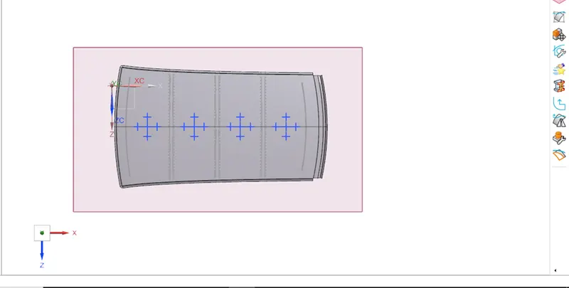
Here before the calculation all the terms like Iy, Rx, Ry, s, α, Lx, Ly these are all calculated manually using the measure tool.
Initially the moment of inertia is calculated for all the roof rails they are as follows:-
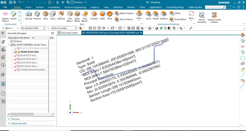
Front roof rail. (we need to consider the minimum moment of inertia here for all components)
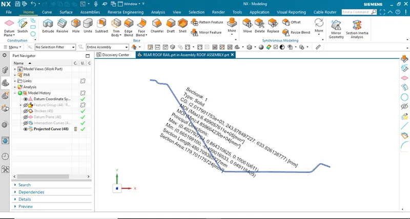
Rear roof rail.
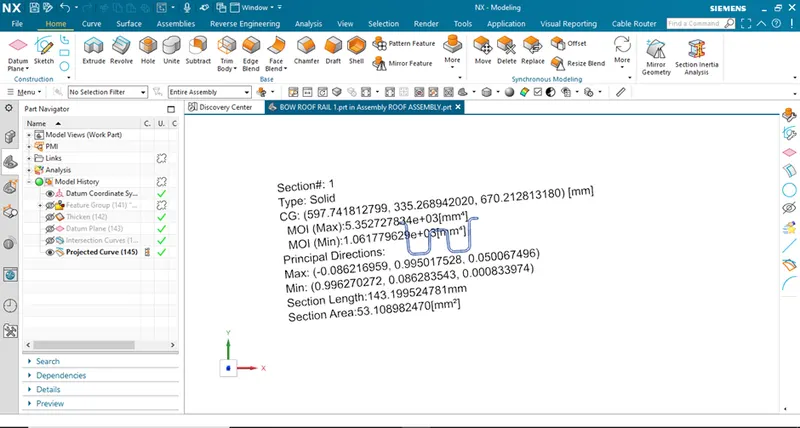
Bow roof 1.
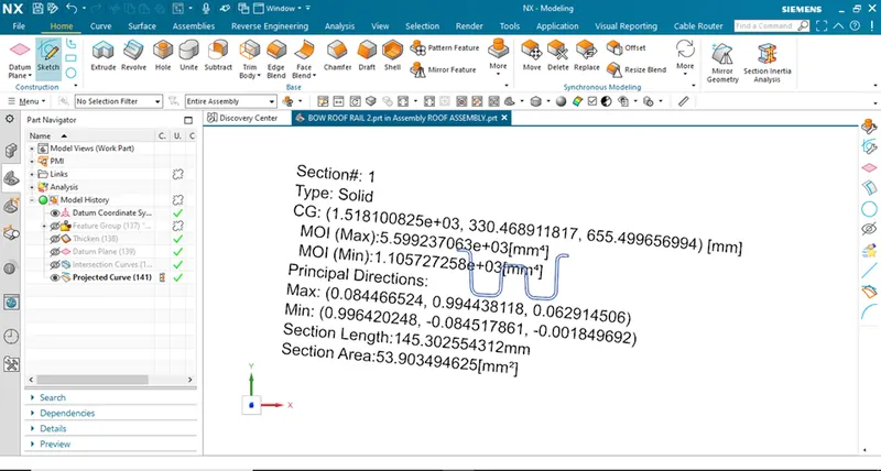
Bow roof 2.
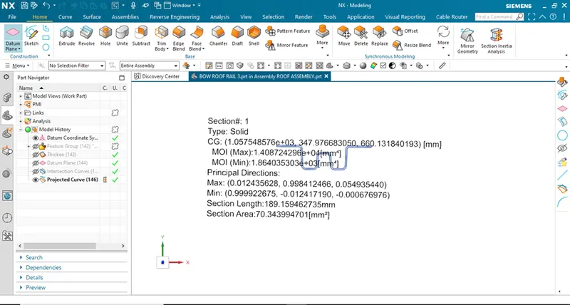
Bow roof 3.
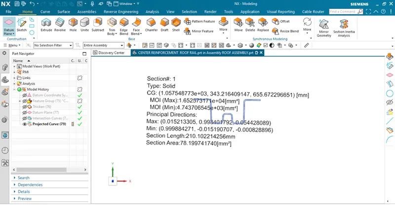
Reinforcement centre roof rail.
|
Sr no. |
Component |
Moment of inertia Iy |
|
1. |
Front roof rail |
7.5607 x 103 mm4. |
|
2. |
Bow roof 1 |
1.061 x 103 mm4. |
|
3. |
Bow roof 2 |
1.1057 x 103 mm4. |
|
4. |
Bow roof 3 |
1.8640 x 103 mm4. |
|
5. |
Reinforcement centre roof rail |
4.7437 x 103 mm4. |
|
6. |
Rear roof rail |
4.8596 x 104 mm4. |
Now as all the Iy values are found out the calculations are done and the following results are drawn:-
|
Sr no. |
Cases |
Condition |
s= L1/2 + L2/2 |
Qr Calculated values |
|
1. |
Front roof rail to bow roof 1 |
Qr>3.1 |
481.205 |
9.748 |
|
2. |
Bow roof 1 to bow roof 3/centre roof rail. |
Qr>3.1 |
461.33 |
10.456 |
|
3. |
Bow roof 3/centre roof rail to bow roof 2. |
Qr>3.1 |
476.14 |
12.201 |
Hence from the above observation of the calculations we can conclude that the roof have cleared the snow load condition.
And finally we have completed the snow load criteria calculation.
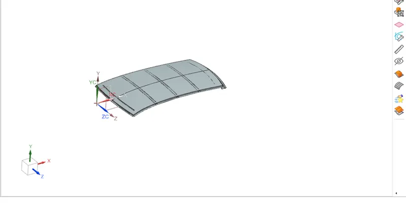
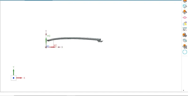
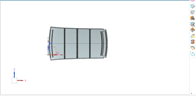
Hence the roof design is completed successfully by clearing all the designing criteria.