Roof challenge
To design a roof and to calculate the and to calculate the heat distortion, snow load criteria for the roof and to conduct a section inertia analysis on the various components
Roof:
An automotive roof is the top portion of the vehicle, that sits above the passenger compartment and protects the passengers from the harsh external elements such as the sun, rain and such.
A roof is usually made of metal or an alloy but with technological advances, they are starting to be manufactured out of composite material which decreases the overall weight of the vehicle dramatically as the roof is major component in a vehicle.
There many variations or types of roofs in today’s world and they are usually classified as:
- Hardtops
- Convertible Roof
- Targa Tops
- Vinyl Roofs
Roof Components:
The roofs consists of multiple components to hold it and to give it the structural integrity to withstand failure in most normal conditions. The supporting structures are placed on the inner panel of the roof, so as to not disturb the aesthetics of the vehicle while at the same time providing the necessary strength to support the roof and keep it from deforming and intruding into the cabin space during a rollover incident. Theses structural components are mentioned as below :
- Centre Roof Rail (CR)
- Bow Roof (BR1, BR2)
- Front Roof Rail (FR)
- Rear Roof Rail (RR)
The above-mentioned components have been designed based on the data that was provided. The master sections of the front and rear roof rail along with the outer skin data of the roof were provided and is shown below
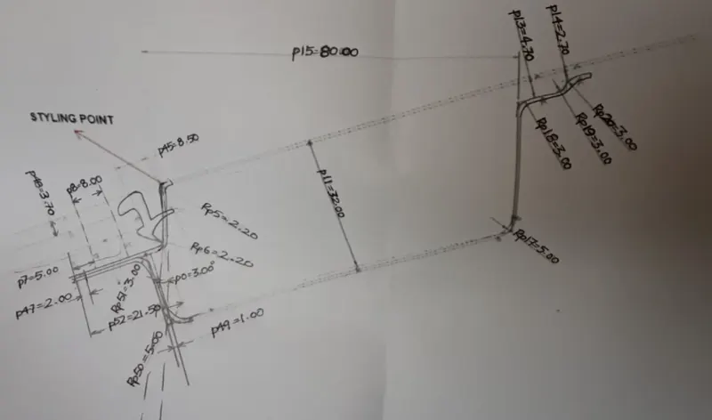
Front Roof Rail Master Section
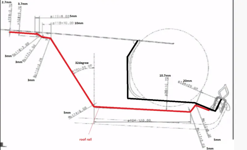
Rear Roof Rail Master Section
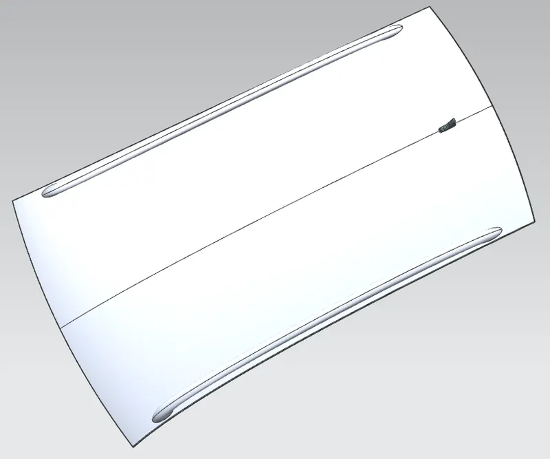
Skin Data for the Roof
Front Roof Rail:
The component that sits at the very front of the roof and hold the roof panel, the windshield and connects them to the A-Pillar of the vehicle is known as the Front Roof Rail. The thickness of the front roof rail is 0.75 mm and the front roof rail design is of the utmost importance as the change is design directly affects the visibility out of the cabin and also the headroom space which is important when it comes to passenger safety requirements.
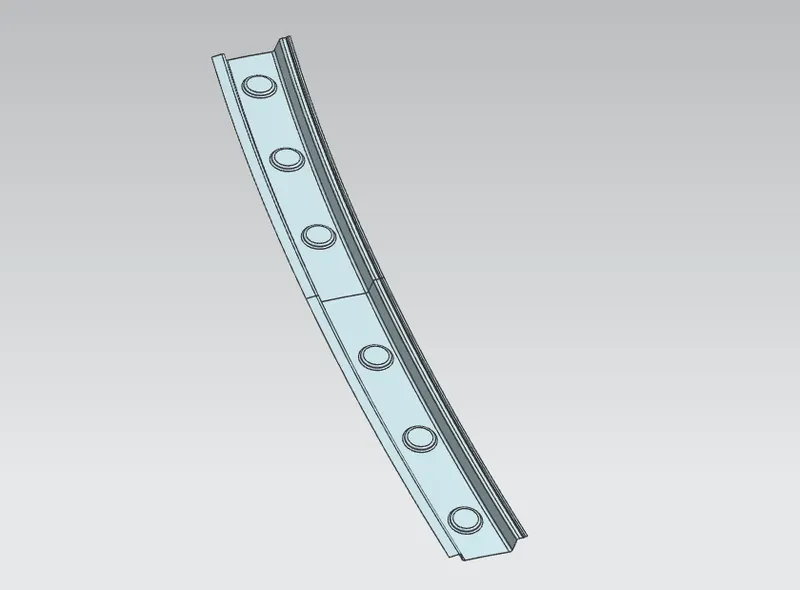
Bow Roof Rail:
The bow roof is the component that is added to provide extra strength to the roof in the required section. A bow roof is not a mandatory structure as the use and placement of it purely depends on the inherent strength of the roof. The number of bow roofs used in a vehicle also vary based on these criteria. In this design study, 2 bow roofs were used, one on either side of the centre roof rail to provide strength in the front and read sections.
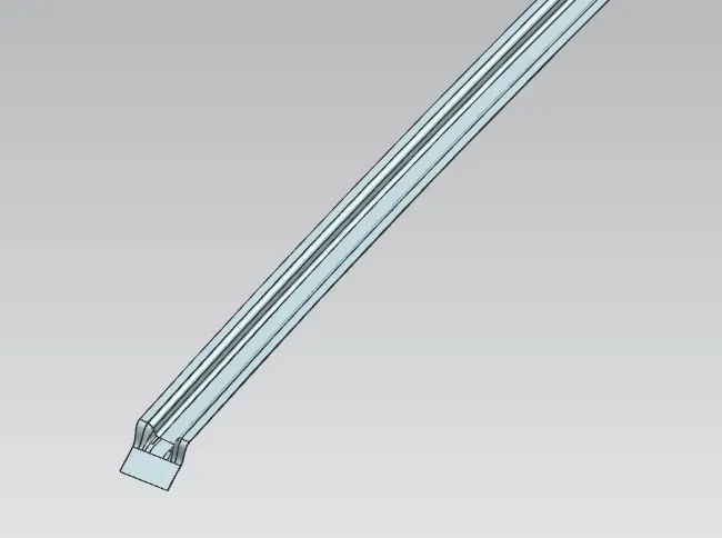
Bow Roof 1 - Placed between the Front & Centre Roof Rail
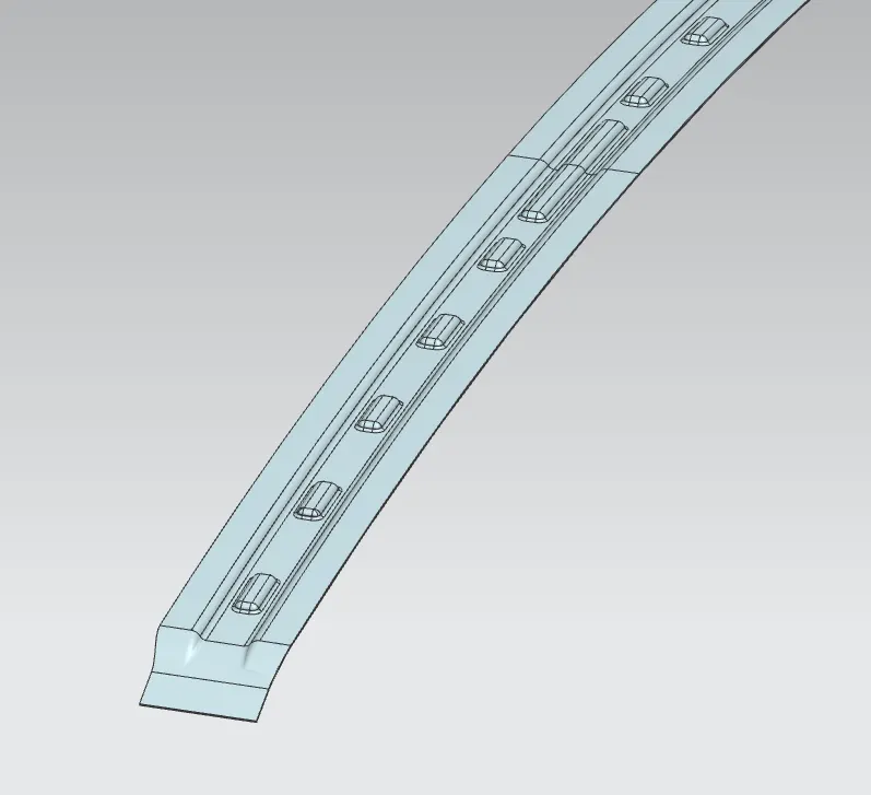
Bow Roof 2 - Placed in between the Centre and Rear Roof Rail
It can be seen that the second bow roof has been given a set of embosses, this was done to increase the strenght locally.
Centre Roof Rail:
The centre roof rail is as the name suggest, a structural component that is placed at the centre of the roof. Unlike the bow roofs, this is not an optional structure and all vehicles tend to have this as it provides strength half way down a long sheet metal component. The centre roof rail in this particular design has a thickness of 1.5 mm instead of 0.75 mm like the other structural components as the reinforcement rail has been integrated into the centre roof rail. The other way to design this would be to use a sandwich structure, one above the other. But an integrated structure design was taken for this case, and hence the centre roof was made much wider than the other bow roofs and the thickness is doubled to have the same effect. A gap of 5 mm was provided between the center roof and the roof panel as this is the clearance provided for the mastic sealants to attach the roof to the roof rail.
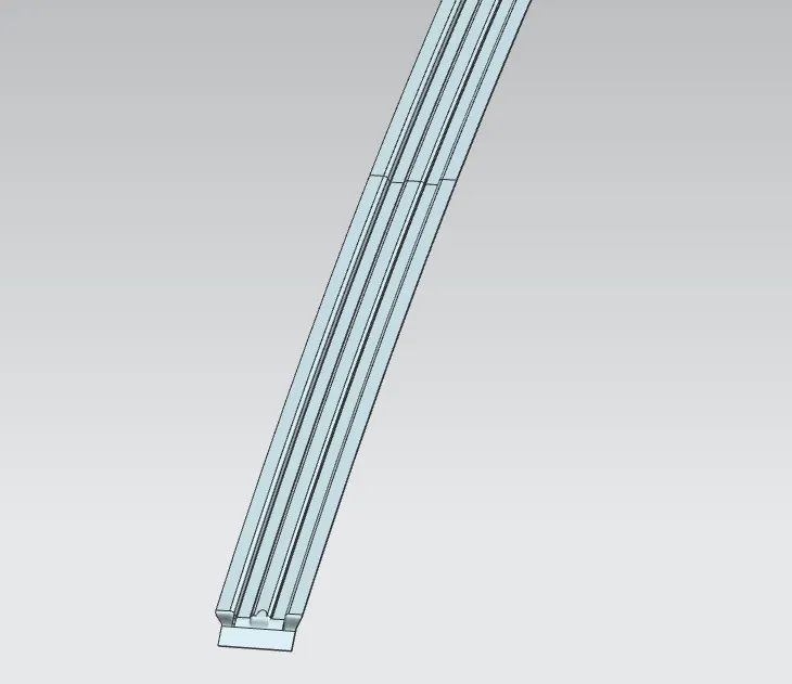
Rear Roof Rail:
The rear roof rail, is similar to the front roof rail, but as the name suggests once again, it sits at the rear most part of the roof and holds the roof panel to the D pillar and will also hold the hinge mechanism for the door of the boot. The rear roof rail’s design , like the front roof rail, will determine the headroom clearance and the rear visibility of the vehicle. A thickness of 0.75 mm was used for the read roof rail.
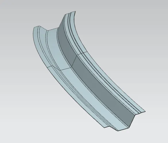
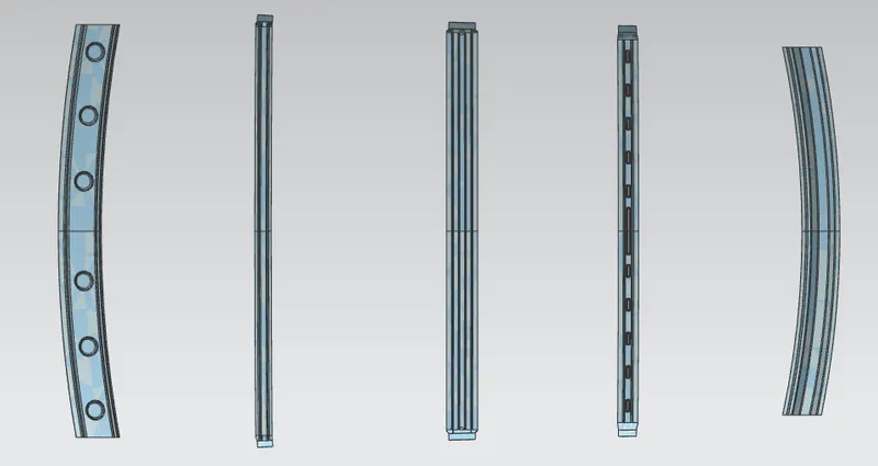
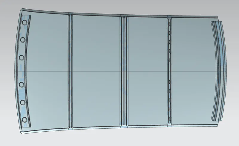
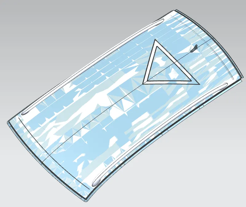
The images below show the all the components together in the design and the complete roof
Heat Distortion Criteria:
The Heat Distortion formula is used to calculate the viability of the roof to withstand the deformation due to change in temperatures which may vary from very high temperature to extremely low temperatures. Under high heat, the metal tends to distort and this calculation can check if the placement of the reinforcements is correct and if it meets the criteria then the reinforcements help in withstanding the heat distortion of the roof panel.
W = [1.73 x 10^(-3) x L] + [1.85 x 10^(-8) x (R^2)/t] + [ 1.10x10^(-3) x l] - 2.68
Where,
Judgement Condition: OK< 2.7> 3.1
L = Roof Length in X-Direction[mm](Roof dimension in 0-Y)
R = Roof curvature
R = 2(Rx*Ry)/(Rx+Ry)
Rx = X curvature
Ry = Y curvature
t = Roof plate thickness [mm]
l = Bow Roof Span [mm]
Calculations for the Heat Distortion Criteria
| Sl. No | Section | Rx (mm) | Ry (mm) | R (mm) | I (mm) | W | Verified |
| 1 | FR - BR 1 | 5735.164 | 2616.507 | 3593.555 | 412.3822 | 1.607448 | Pass |
| 2 | BR 1 - CR | 4926.847 | 6380.208 | 5560.123 | 466.3172 | 2.110809 | Pass |
| 3 | CR - BR 2 | 3951.161 | 10715.79 | 5773.498 | 383.9917 | 2.079902 | Pass |
| 4 | BR 2 - RR | 3282.691 | 14571.77 | 5358.281 | 435.7106 | 2.022782 | Pass |
From, the above table, we can conclude that the placement and design of the roof components meets the heat distortion criteria in all the sections.
Snow Load Prediction
The snow load prediction is done especially in countries where there is a lot of snowfall. It is a precautionary calculation done to see if the roof of the vehicle can effectively take the load of the snow that accumulates on top of the roof without causing the roof to deform. There is a formula for this calculation and it is given below,
Qr = [Iy x t2] / [α x s x [(Rx + Ry)/2]2 x 10-8]
Where,
α = My x Lx2 x 10^-12 , My = Y(Ly-Y)
Judgement condition = Qr ≥ 3.1
250 ≤ s ≤ 380
t = Roof plate thickness [mm]
Ly = Distance between the front and rear roof Rails on the Vehicle along with 0Y[mm]
Length of Roof panel with the centre point between Roof rail Front /Rear as the front and rear reference point.
Lx = Distance between the Left and Right end of the roof on the Roof BOW [mm]
Width of the roof panel exposed on the surface.
Y = Distance front Roof Rail to Roof BOW[mm]
s = Distance for which Roof BOW bears divided load [mm]
s = L1/2 + L2/2
Iy = Geometrical moment of inertia of Roof BOW (Y cross-section) [mm4]
Rx = Lateral direction curvature radius of roof panel Y cross-section on Roof BOW [mm]
Roof panel curvature Radius of the Laength Lx in Front view
Ry = Longitudinal Direction curvature radius of the Roof panel X cross-section on Roof BOW [mm]
Roof panel X curvature radius of length s in Side view
Calculation for Snow Load Prediction
| Sl. No | Iy (mm^4) | t (mm) | α (mm^4) | s (mm) | Rx (mm) | Ry (mm) | Rx+Ry | Qr | Judgement |
| 1 | 789.987 | 0.75 | 0.965444 | 508.5125 | 4543.6625 | 2639.7439 | 7183.4064 | 7.016374 | Pass |
| 2 | 1400.301 | 0.75 | 0.935543 | 488.4028 | 3772.6047 | 6269.8443 | 10042.449 | 6.837269 | Pass |
| 3 | 81.26394 | 0.75 | 0.793947 | 477.6467 | 4286.5387 | 11246.81 | 15533.349 | 0.169522 | Fail |
From the above table, it can inferred that the current design passes for the snow load criteria in the first two sections and fails in the third. The third roof bar was modified multiple time, by varying its thickness, width and adding embosses but the snow load criteria fails in the third section in all conditions. Hence to negate this, an emboss is given in that section of the roof panel to increase the strength of the panel locally.
Draft Analysis
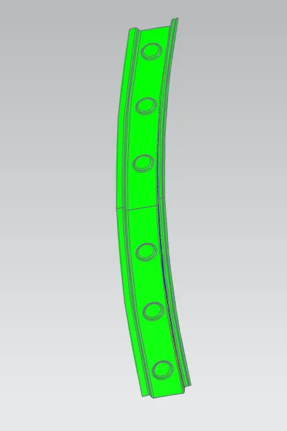
The draft analysis was conducted on all the components to check if it can be manufactured. the images below show the results of the draft analysis
Analysis for Front Roof Rail
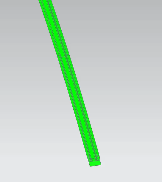
Analysis for Bow Roof 1
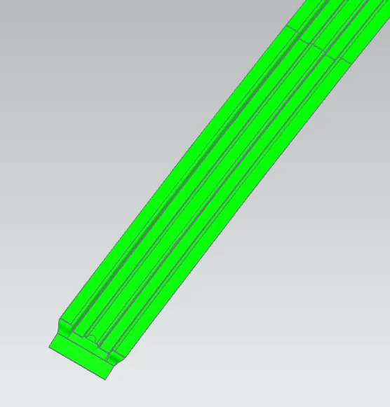
Analysis for Centre Roof Rail
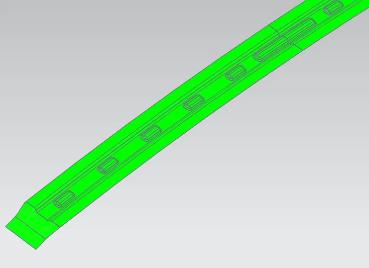
Analysis for Bow Roof 2
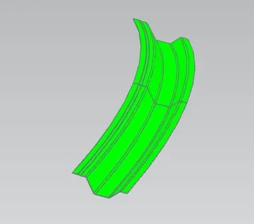
Analysis for Rear Roof Rail
The components for the roof were created, which were the front roof rail, the bow roofs, the center roof rail integrated with a reinforcement and the rear roof rail. The design was checked to see if it passes the the heat distortion criteria and the snow load prediction and finally a draft analysis was conducted.