Roof challenge
AIM DESIGN OF ROOF BY THE GIVEN STLYING CLASS A SURFACE & MASTERSECTIONS AS PER THE OEM STANDARDS.
DESCRIPTION CREATION OF DITCH AREA ,FRONT ROOF RAIL,REAR ROOF RAIL, BOW ROOFS,& CENTRE REINFORCEMENT,FLANGES WITH THE GIVEN STLYING ,BY FOLLOWING THE MASTER SECTIONS as per the oem standards.
INTRODUCTION ROOF
it is an automotive part of the car body which lies on the top of the car its function is to cover the top area by protecting not to allow the sun heat ,wind,rain 7 other external elements.
RED COLOUR HIGHLIGHTED IS THE ROOF PART OF THE CAR BODY.
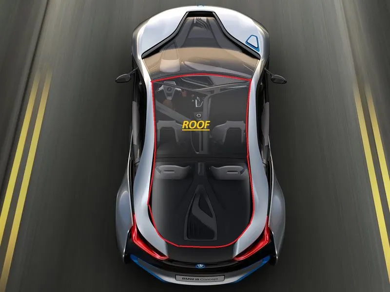
THE ROOF IS FIXED WITH THE BODY SIDE FEATURES ,A PILLAR B PILLAR & C PILLAR & THIS ROOF AS BOW ROOFS REINFORCEMENTS & PANELS FLANGES TO STRENGTHN THE PART.
THERE ARE VARIOUS TYPES OF TOOFS.IN THE AUTOMOTIVE SECTOR AS PER THE MODEL & RANGE OF THE CAR,& PRICE ALSO VARIES. WITH DIFFERENT STYLES.
1. SUNROOF
2.PANOROMIC ROOF
3.TARGA TOPS
4.T-TOPS
5.VINYL ROOFS
6.HARD TOPS
7.CONVERTABLE ROOFS
PANOROMIC ROOF
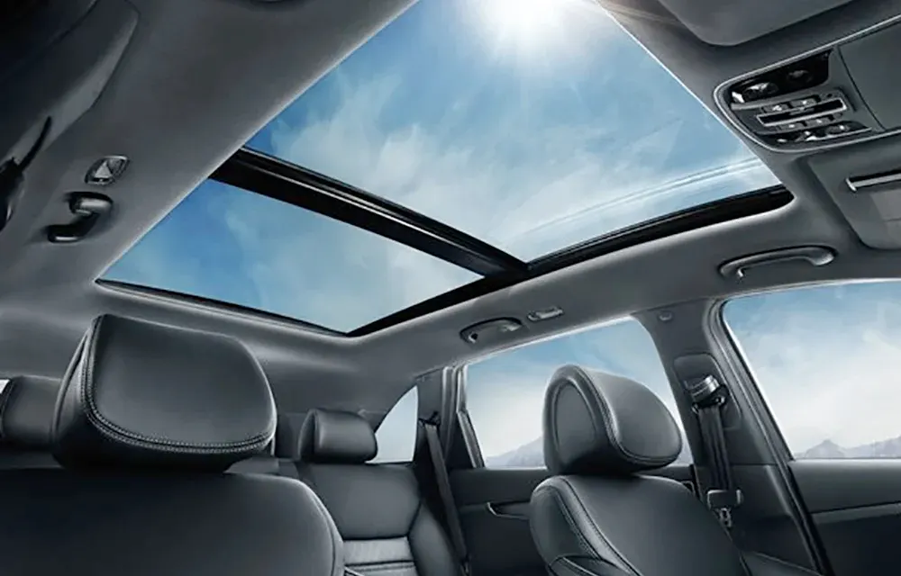
TARGA ROOF
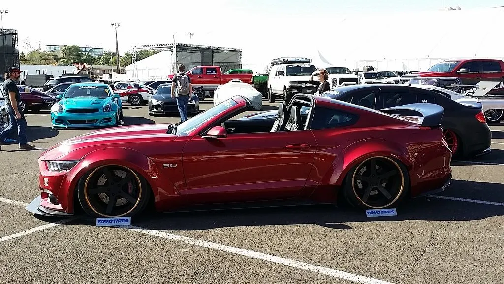
T TOPS
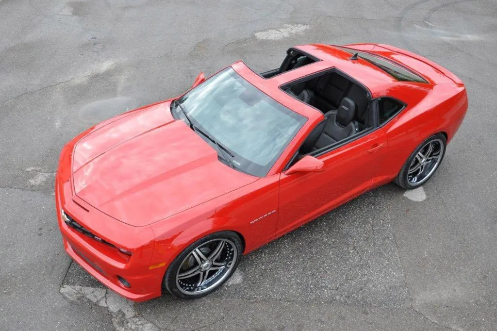
CONVERTABLE ROOFS

HARD TOPS
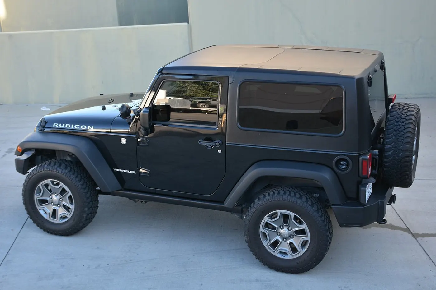
THE DESIGN CONSIDERATION STO BE FOLLLOWED WHILE DESIGNING THE ROOF
1.VISIBILITY CRITERIA
2.HEAD CLEARANCE
3.SAFETY
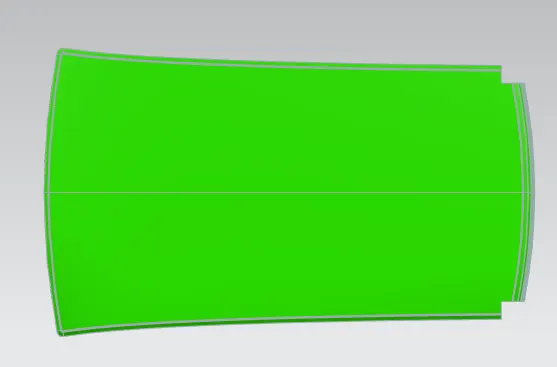
4.DRAFT ANALYSIS OF 3 deg
5.HEAT & SNOW LOAD DISTORATION
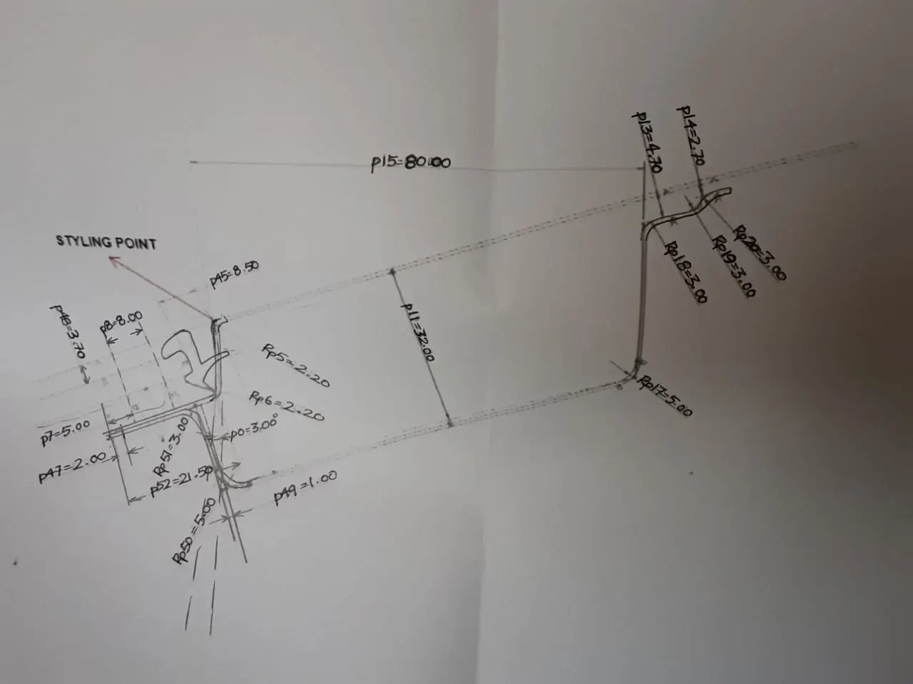
MASTER SECTIONS & STLYING GIVEN AS INPUT TO DESIGN THE ROOF.
STLYING SURFACE
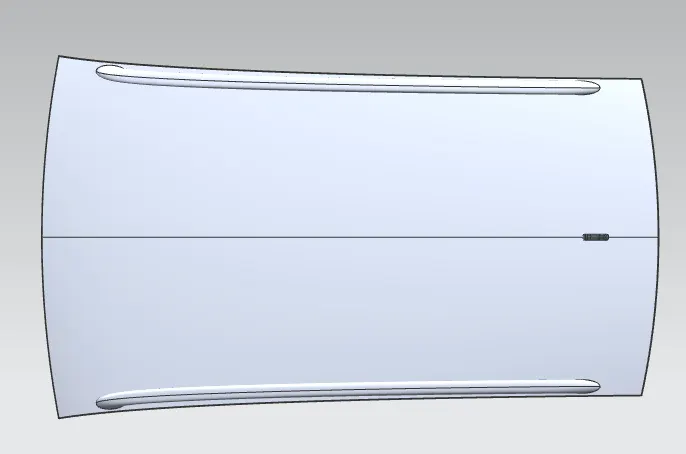
FRONT ROOF RAIL
REAR ROOF RAIL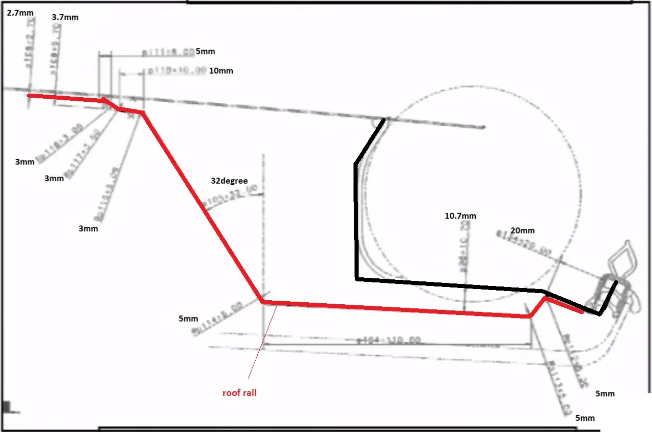
BOW ROOFS
REINFORCEMENT
DESIGN PROCEDURE OF THE OUTER PANEL\
Extract the given class a at one side & untrim it to remove the excess part by projecting the given class a surface then create the offset as per the master sections to get the desired part.
the blend radius min is 3=0.75 thickness .i have given is 5 mm.
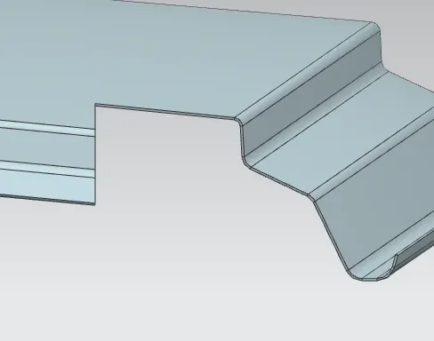
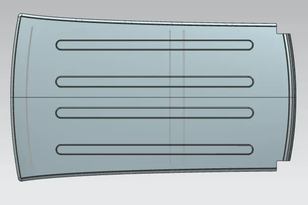
created the embosses & trimed some part so that the part wiil get more strength & also to reduce the weight of the component.
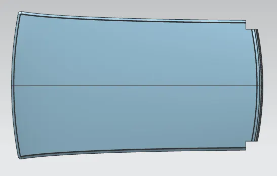

FRONT FLANGE
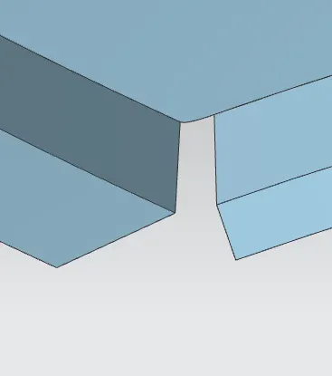
REAR FLANGE & PART THICKNESS OF 0.75mm
DRAFT ANALYSIS OF OUTER PANEL WITH 3 deg .is clear.
DESIGN OF FRONT ROOF RAIL
This panel acts as the support of the outer panel deigned as per the master sections
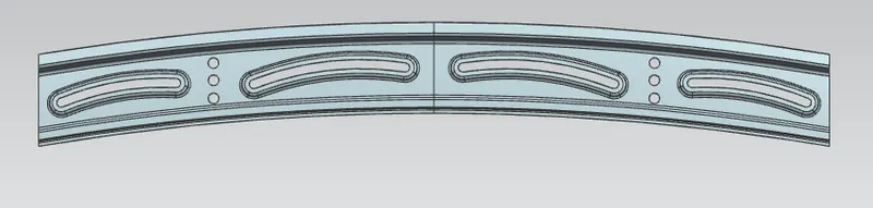
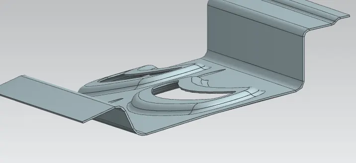
DRAFT ANALYISIS OF FRONT ROOF RAIL
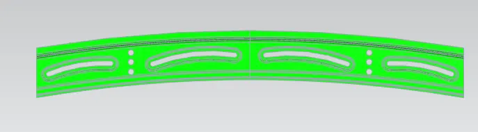
BOW ROOFS ALL THE 3 BOW ROOF S ARE DESIGNED IN THE SAME PROCEDURE.
BOW ROOF ACTS AS THE SUPPORT OF THE OUTER PANEL & ONLY THE EDGE PART WILL BE JOINED TO THE OUTERPANEL FLANGE IT IS WELDED WITH SPOT WELD & THE MIDDLE OF THE PART IS JOINED WITH THE RUBBER MASTICS .THE GAP B/W THE OUTER PANEL & THE BOW ROOFS MAINTAINED IS 5 MM EACH BOW ROOF.
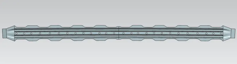
TRIMS PROCESS BY OFFSETING THE SURFCACE
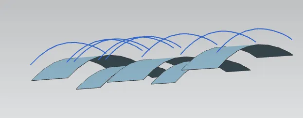
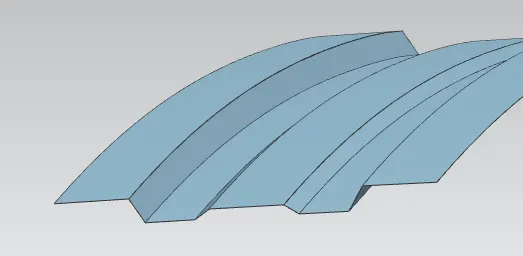
DRAFT ANALYSIS OF BOW ROOFS
BOW ROOF 1
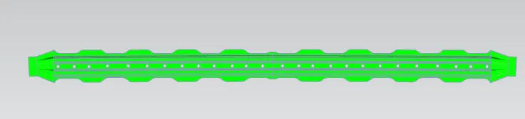
BOW ROOF 2
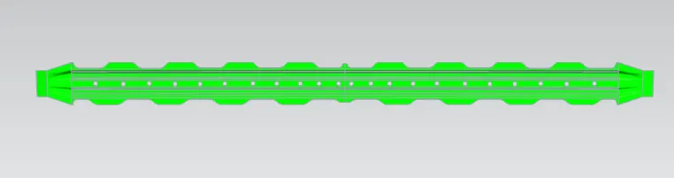
BOW ROOF 3
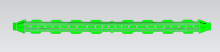
REAR ROOF RAIL
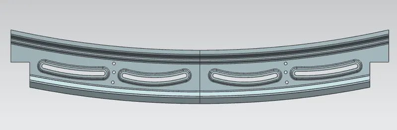
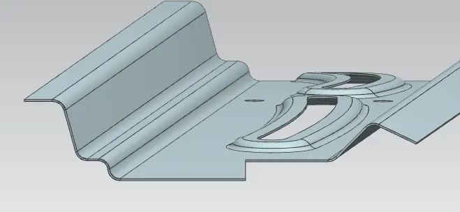
DRAFT ANALYSIS OF REAR ROOF RAIL
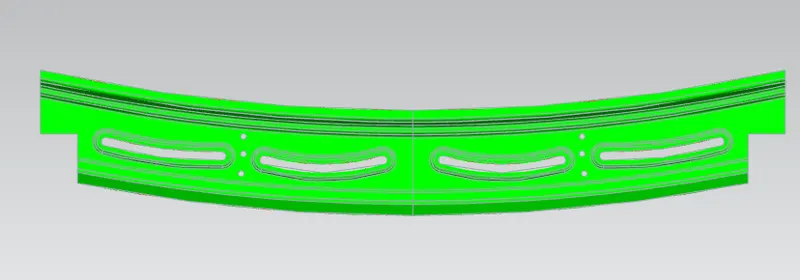
REINFORCEMENT & BOW ROOF
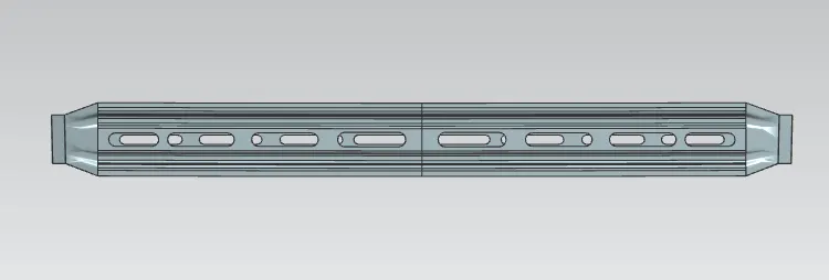
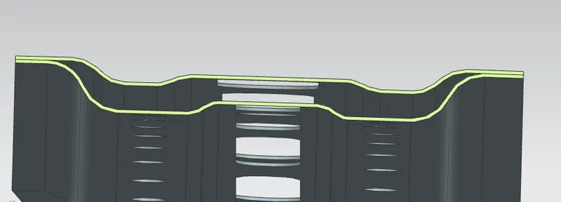
CENTRE RAIL
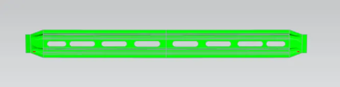
REINFORCEMENT
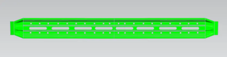
COMPLETE ASSEMBLY
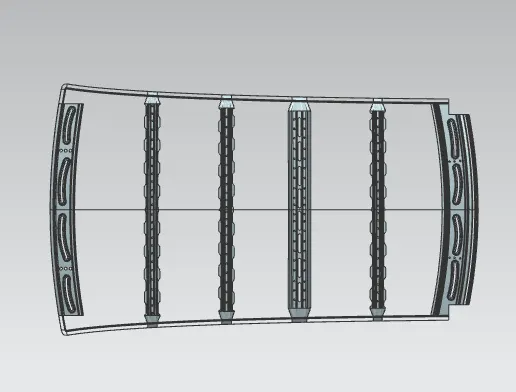
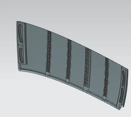
MAINTAINED GAP BETWEEN THE OUTER PANEL THE BOW ROOF SO THAT THEY ARE ATTACHED WITH RUBBER MATERIALS CALLED AS MASTICS.
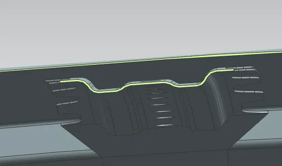
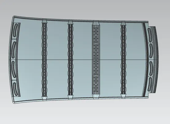
BOTTOM VIEW
HEAT DISTORTION CALCULATION
After the completion of the design completly with thickning this calculatuion is done to check the strendth of the roof in hot conditions. by following method.
W = [1.73 x 10^(-3) x L] + [1.85 x 10^(-8) x (R^2)/t] + [ 1.10x10^(-3) x l] - 2.68
Judgement Condition : OK< 2.7> 3.1
Where
L = Roof Length in X-Direction[mm](Roof dimension in 0-Y)
R = Roof curvature
R = 2(Rx*Ry)/(Rx+Ry)
Rx = X curvature
Ry = Y curvature
t = Roof plate thickness [mm]
l = Bow Roof Span [mm]
TO FIND THE Rx & Ry VALUES SKETCH IS CREATED.
- Create the sketch on the top plane wich seems like on the top on the roof
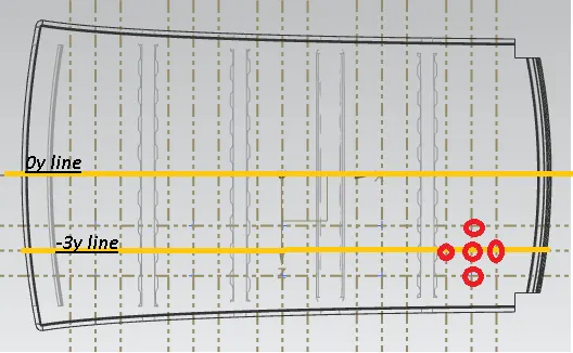
- create the horizontal line exactly in the centre of the roof & offet it downwards 300mm it is called -3y line
- with that -3Y lne offset 100mm both sides
- like wize do it for all the bow roofs 3 horizontal & 3 vertical lines will be created .& make all the line as redferance line
- the intersection points which is highlighted as red circles in the picture at the point point to be created that is the required point to make the three point arc. & to measure the Rx& Ry value.
- To get the value measured with locad radius command.
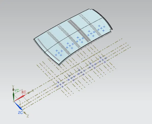
projection points
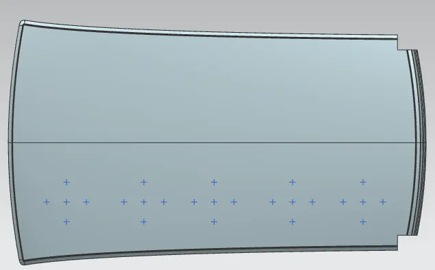
ARC
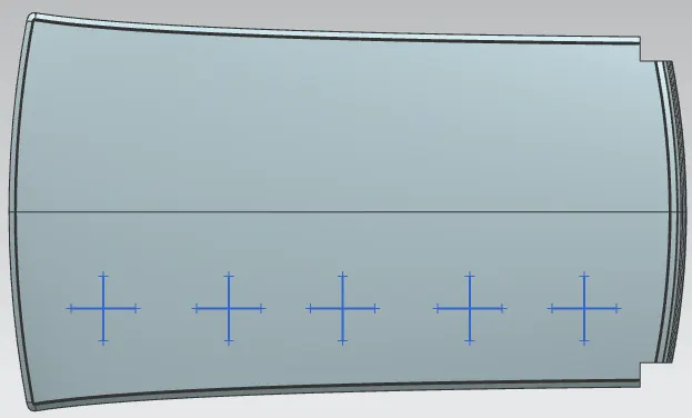
MEAUREMENTS OF RADIUS RX VALUE FROM FRONT ROOF RAIL TO BOW 1
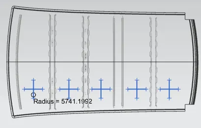
BOW ROOF 1 TO BOW ROOF 2
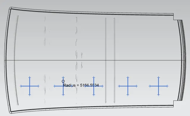
BOW ROOF 2 TO REINFORCEMENT
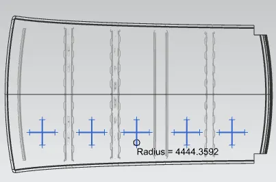
REINFORCEMENT TO BOW ROOF 3
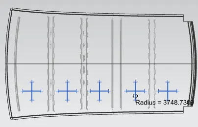
BOW ROOF 3 TO REAR ROOF RAIL
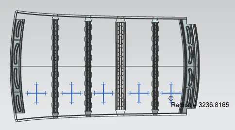
RY VALUE
FR ROOF REAL TO BOW 1
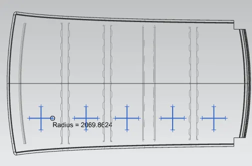
BOW 1 TO BOW 2
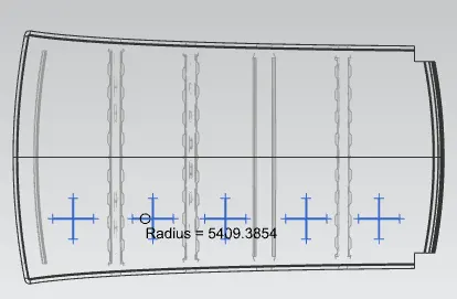
BOW 2 TO REINFORCEMENT
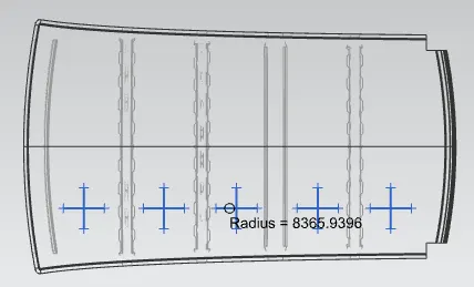
REINFORCEMENT TO BOW 3
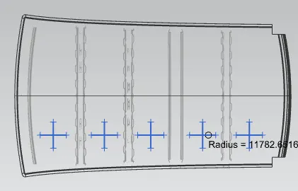
BOW 3 TO REAR ROOF RAAIL
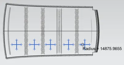
HEAT DISTORTION CALCULATIONS

ACCORDING TO THE JUDGEMENT CRITERIA OK<2.7>3.1,ALL VALUES ARE SATISFIED.
SNOW LOAD CALCULATIONS
Qr = [Iy x t2] / [α x s x [(Rx + Ry)/2]2 x 10-8]
Note: The Qr value given over here is correct. There was a typo error in the formula given in the video.
Where
α = My x Lx2 x 10-12 , My = Y(Ly-Y)
Judgement condition = Qr ≥ 3.1
250 ≤ s ≤ 380
t = Roof plate thickness [mm]
Ly = Distance between the front and rear roof Rails on the Vehicle along with 0Y[mm]
Length of Roof panel with the center point between Roof rail Front /Rear as the front and rear reference point.
Lx = Distance between the Left and Right end of the roof on the Roof BOW [mm]
Width of the roof panel exposed on the surface.
Y = Distance front Front Roof Rail to Roof BOW[mm]
s = Distance for which Roof BOW bears divided load [mm]
s = L1/2 + L2/2
Iy = Geometrical moment of inertia of Roof BOW (Y cross-section )[mm4]
Rx = Lateral direction curvature radius of roof panel Y cross-section on Roof BOW [mm]
Roof panel curvature Radius of the Length Lx in Front view
Ry = Longitudinal Direction curvature radius of the Roof panel X cross-section on Roof BOW [mm]
Roof panel X curvature radius of length s in Side view
projected points
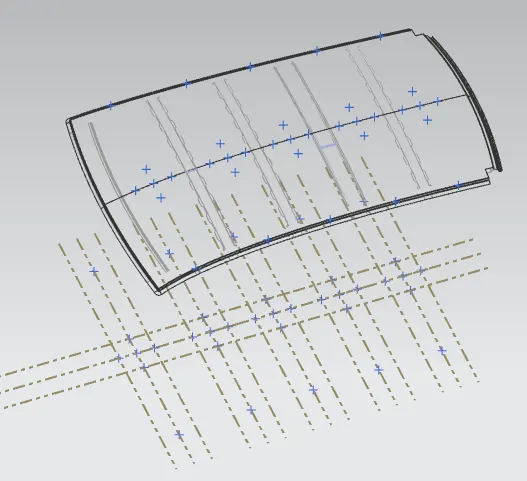
ARC OF RX & RY
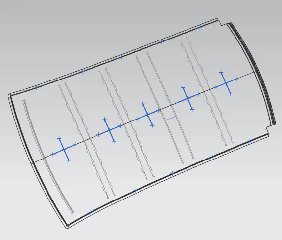
RX VALUES OF SNOW LOAD
FR ROOF RAIL TO BOW 1
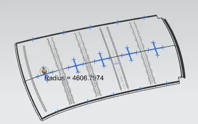
BOW 1 TO BOW 2
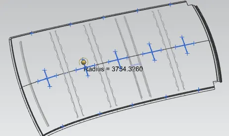
BOW 2 TO REINFORCE MENT
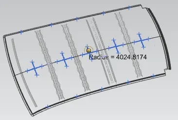
REINFORCEMENT TO BOW 3
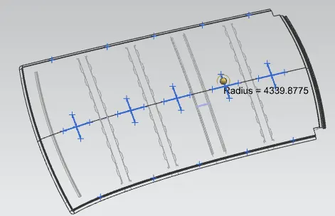
BOW 3 TO REAR ROOF RAIL
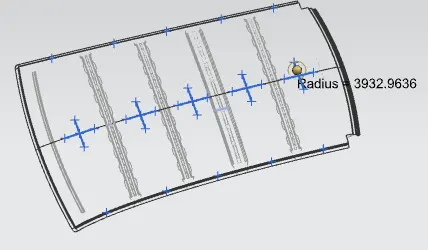
RY VALUES OF SNOW LOAD
FR ROOF TPO BOW 1
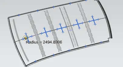
BOW 1 TO BOW 2
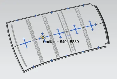
BOW 2 TO REINFORCEMENT
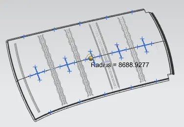
REINFORCE NT TO BOW 3
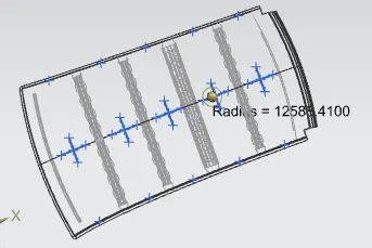
BOW 3 TO REAR ROOF
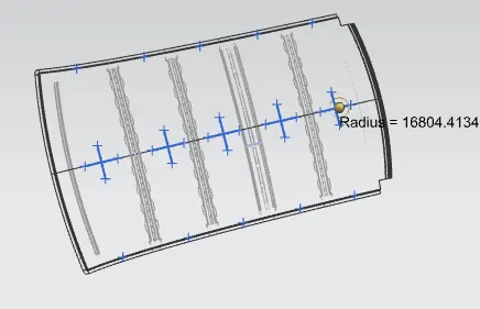
GEOMETRICAL MOMENT OF INERTIA OF BOW ROOFS
BOW ROOF 1
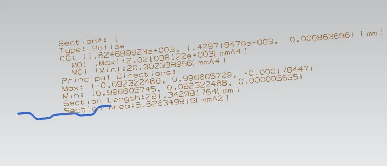
BOW 2
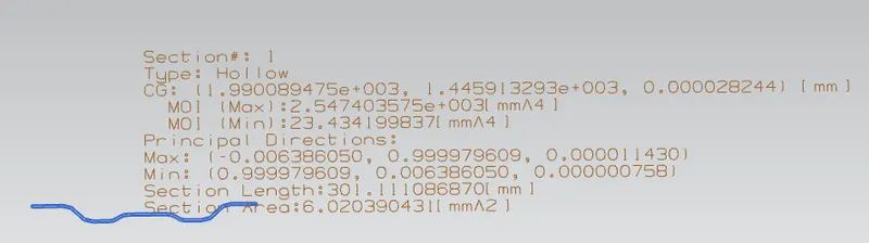
CENTRE REINFORCEMENT
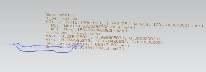
BOW ROOF 3
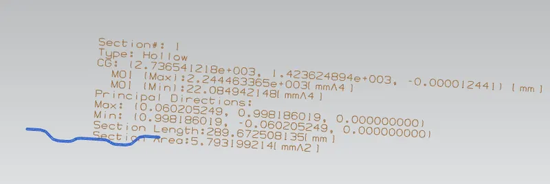
CALCULATIONS OF SNOW LOAD DISTORATION

Judgement condition = Qr ≥ 3.1
250 ≤ s ≤ 380
AFTER DOING THE CALCULATIONS FROM BOW ROOF 2 BOW 3 THERE IS LESS STRENGTH ON THE OUTER PANEL IT IS NOT SATISFYING THE JUDGEMENT CONDITIONS.
SO THAT I HAVE CREATED THE EMBOSSES ON THE OUTER PANEL TO GIVE SOME STRENGTH.& TO BEAR THE SNOW LOAD CONDITION. ATTACHED THE IMAGES BELOW.
CONCLUSION
DESIGN OF ROOF IS DONE,OUTER PANEL,FRONT ROOF RAIL,BOW ROOFS,REAR ROOF RAIL,& CENTRE REINFORCEMENT IS CREATED BY FOLLOWING THE MASTER SECTIONS & PERFORMED DRAFT ANALYSIS.& CALCULATIONS OF HEAT DISTORATION & SNOW LOAD IS DONE IS OK.
IN SNOW LOAD 3 & 4 POSITIONS I HAVE NOT SATISFIED THE REQUIRED JUDGEMENT.
SO THE I HAVE CREATED THE EMBOSSES ON THE TOP OF THE OUTER PANEL PASSING THROUGH THE NOT SATISFIED BOW ROOFS IT CAN INCREASE THE STRENGTH OF THE OUTER PANEL AT THET AREA.& ATTACHED THE IMAGE IN THE ABOVE.
ALL THE IMAGES OF ROOF ASSEMBLY & FILES ARE ATTACHED ABOVE IN THE ANSWER BOX