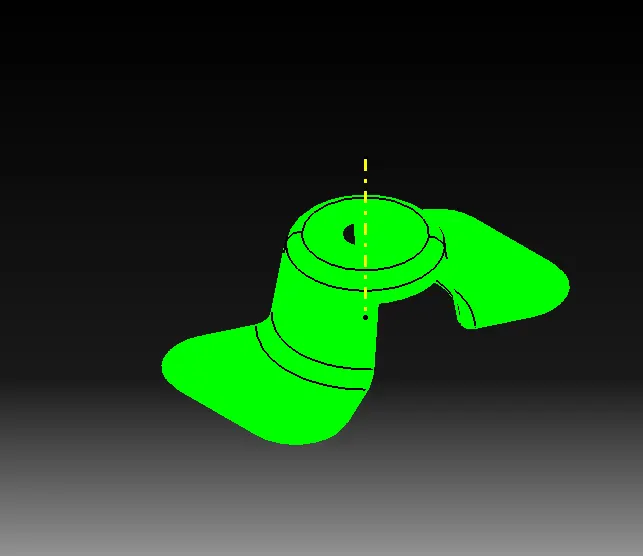
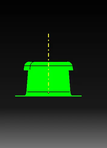
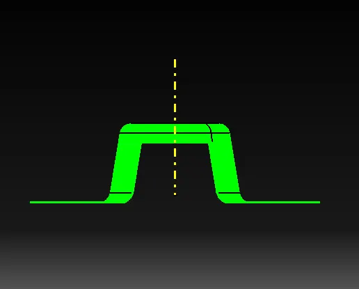
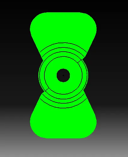
Week 8 - Challenge 1 - Draft Analysis on a Fan Cover
AIM : DRAFT ANALYSIS & TOOLING AXIS CREATION ON FAN MODEL.
DESCRIPTION: How to create draft analysis & tooling axis by using line command steps
To design a plastic component should follow the design rules
TOPIC: core &cavity design in this sub concepts like
DRAFT
EJECTOR
SIDECORE
LIFTER
UNDERCUTS
1.DRAFT : It allows for parts to release from the mold easily
Draft is required on all parts in the direction of the mold movement in order to allow parts to release or eject from the mold properly
Draft is an angle In which the part is tapered to allow it to release easily
FOR INSTANCE: when an plastic material is heated in to molten state & cooled it will stick to the parts which is attached to it &difficult to release from it to avoid that draft is used in plastic design aspect
Adding draamft helps to release the part easily.
The minimum Draft angle is 1/2 to 3 deg.
The most widely used angle is 3 degas per the norm. Perspective.
TOOLING AXIS: The direction in which mold opens &closes is the tooling axis.
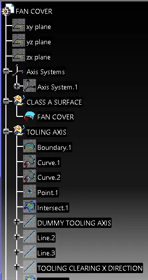
The tooling axis is created on the class a surface
Firstly check weather all the the edges of the part all closed by using the boundary command check it properly by rotating the part model clearly.
After that intersect the boundary into to parts (disassemble) it .
Create the point on the center of the hole of the class a surface
Before creating a point check the the correct direction which we can create the tooling axis easily & in proper manner.
Create the point by curve ,circle ellipse.
Create the axis system.
Intersect the part in to to parts by intersect command. Select zx plane. & part ok.
Create a dummy tooling axis in the middle with point reference in z direction.
Hide alll the unnecessary lines. Show the intersect line .and create the point to point line & enlarge it. Same as other side.
After creating the two lines.
BISECTING line is to created
Select the line command bisecting option. Select the two line (point to point lines) &select the point as reference check weather the line is in z direction.
Ok
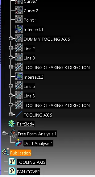
Name the bisecting line as tooling clearance x direction.
As the same create the two point to point line in y direction create bisection line in (Yz plane.)
Name it as tooling clearance y direction.
After creating the two x&y direction line
Create the Main tooling axis by line command bisecting.option select line 1&line to and point as created & check the line is creating is correct direction.ok.
After the tooling axis is created. Make the line thick & change the colour.
PUBLISH.
the use of publication is to easily getable in tge class a surface
To create publication select the tooling axis goto tools select publication.ok.
After the publication is created
Draft analysis is to be done.goto insert ,analysis, feature draft analysis click ok.
Popup is visible.
Select the compass draft direction option
Drag the compass on the red point and coincide it to the axis line the W should be in the upper side direction & lock it after it is properly directed.
Select the part &click on it the part changes into tge green colour so that the part is ready to make the draft .
Check the draft angle by giving tge 3 deg angle &analysis it by selecting the tool.in display feature.
Now thw fan cover is used to make the draft .
DRAFT ANALYSIS ON FAN COVER