Radar Mast & Final Assembly of Yacht
MODELING AND RENDERING OF YATCH ASSEMBLY USING SOLIDWORKS
OBJECTIVE-The main objective of this project is to creat solid model of yatch with various parts in solidworks
How to assemble the sketched parts of the yatch
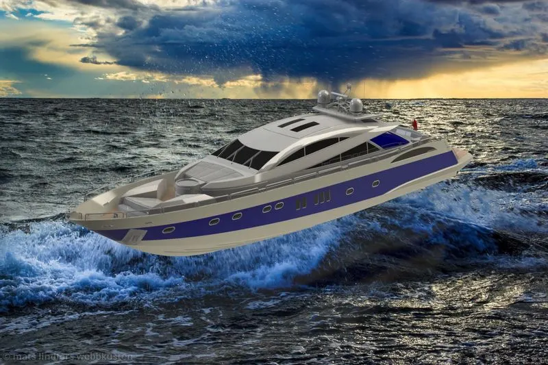
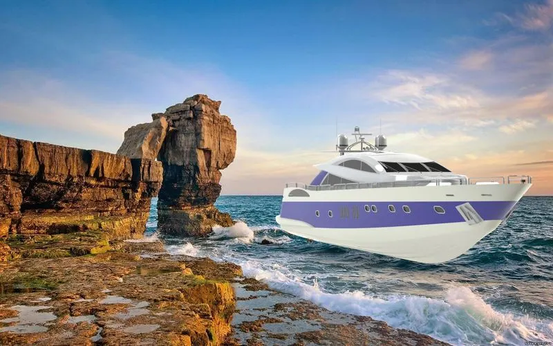
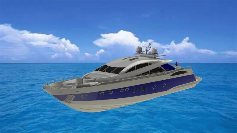
Then to create the rendering images for the realistic view of the yatch assembly using solidworks visualize,& photo view 360.
INTRODUCTION-Here in ths project aim to model the yatch using solidworks using various features commands,and apply apperances renders so that to be in exact in realistic view. this software is mainly used to model 3d parts using 2d sketch .the yatch has the parts like hull,superstructure various seat ,are assembledthe components by the mate commands.applying of decals and rendering it with solidworks visualize.
The different components of yatch assemble are
- propellor
- Radar
- Hull
- Superstructure
- Front seat of yatch
- Rear seat of yatch
- Middle seat of yatch
- Garrage door
- Radarmast
The next step after designing the part components, applying the apperrances to the different part model,after that assemble the part components by the mate features by giving the required relations
than adding the photoview 360 rendering visualize images , camera view using visualize
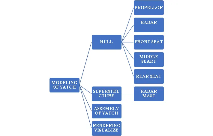
The above parts are designed step by step, explained in the next step by the flow chart
FLOW CHART
EXPLANATION OF THE FEATURES APPLIED TO DESIGN THE YATCH MODEL
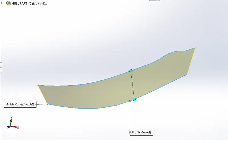
SURFACE LOFT
The surface loft is the main feature in the modeling of yatch. the lofted surface creates a shspe between the multiple profiles land guide curves, this is a valuable tool for modeling complex surfaces.
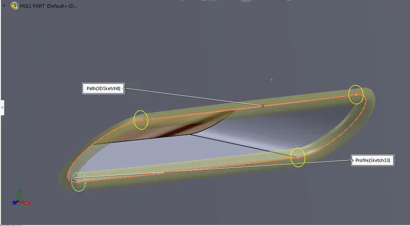
SURFACE SWEEP/SWEEP CUT: Sweep creates a base, boss, cut, between the two profiles,according to the rules the profile must be closed for a base or boss sweep feature, the profile may be open or closed for a surface sweep feature
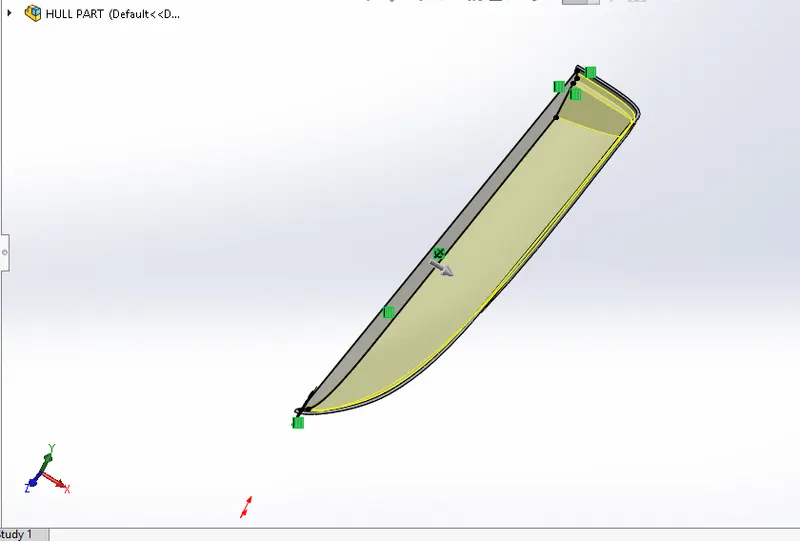
EXTRUDE BOSS BASE/SWEEP BOSS BASE :
The extrude boss base is the most basic nd important feature in the solidworks this features extrudes the sketch along the straight line, in this feature we can apply the thickness feature, draft feature without sketch in the 2d.
REVOLVE BOSS BASE:
This feature adds the materials by revolving a sketch around the axis. the on geomentruy is created in the 2d sketch for the revolve feature the sketch should closed completly, and axis line is compalsory to this feature
TRIM SURFACE : this is the feature is used to remove the excess materials which is sketch & converted into 3d model by selecting the part like wise trim tool ,and tghe part to be removed will be shown in different colours,like yellow & purple. 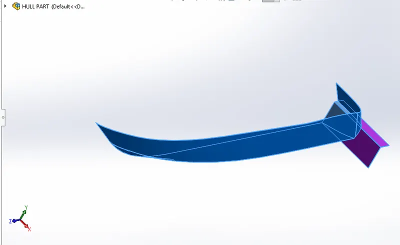
MIRROR: Creates a copy of a feature or (multiple bodies & features) mirrored about a face or a plane. can select the feature, or a face that comprise the feature. bodies to mirror,select a single body in a single model or multybody part to create a mirror entity.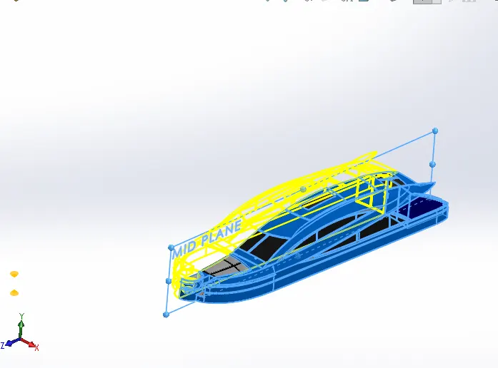
REFERANCE GEOMENTRY: Referance geomentry defines the shape or form of a surface or a solid. Referance geomentry includes items such as planes,axes, coordinate systems, and points. you can use referance geomentry in the creation of several kinds of features.
FILLET: this feature creates a rounded internal or external face on the part. can fellet the edges of a face,edges,loops etc.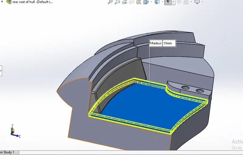
CHAMFER: This feature is used mainly to deduse the unweanted material on th edges by giving tha angle distance or distance distance value. it is onbtained like flat surface. 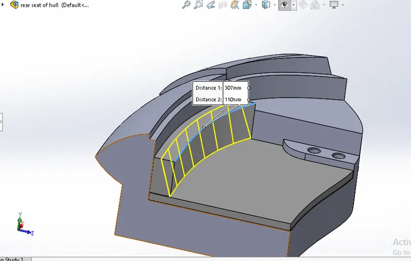
SPLIT LINE; this feature used on the hull at the side view it can be onserved on the offset plane the sketch is drawn and by selecting th spline line fetaure and body to spline option on the feature tree. the split line is directly sketch on the required path.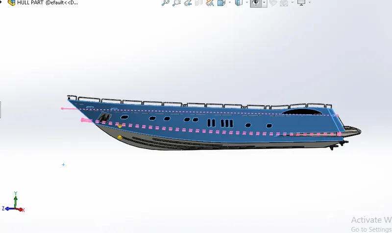
CONVERT ENTITIES & OFFSET ENTITIES: This feature mosty used when the same sketch need to be done on ythe same line is converted instead of redraw of the line & the converted line can be again offset by giving the dimension Or the angle at the required length.by creating new sketch view.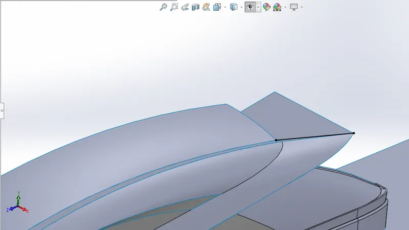
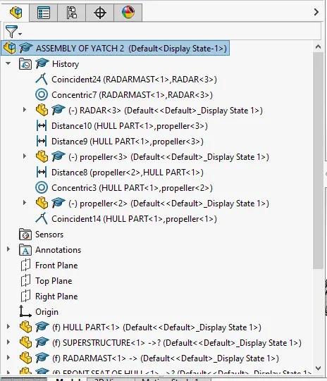
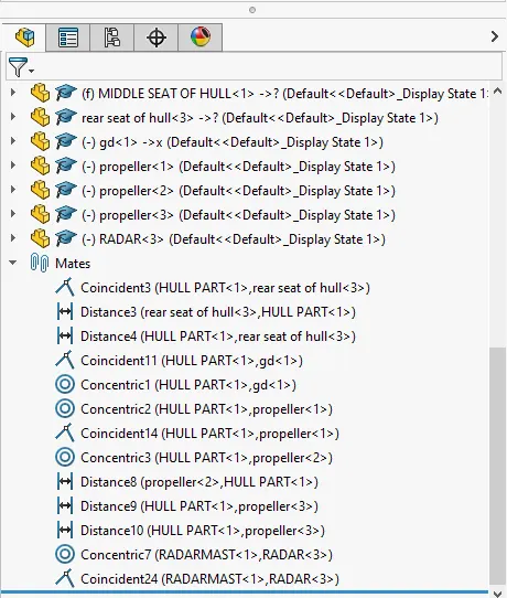
MATE: Mates creates geometric relation ships between assembly components. as you add mates, can define the allowable directions of a linear or rotational motion of te cpomponents. you can move a component with in its degrees of freedom, visualizing the aasembly behaviour.
Advance mates, coincident mates witdh mates are the exmples of mates,
RENDERING ; Rendering is a process of creating realstic images of the photoreastic model with the environment.
Rendering has be doen in two ways in solidworks
photoview 360
solidworks visualize.
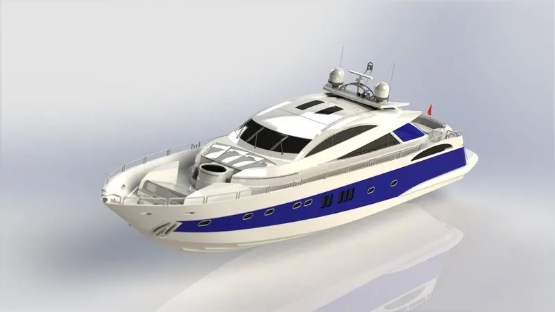
PHOTOVIEW 360: photo view 360 is a visualization and rendering solution which includes with solidworkks . providing high interactive environment for viewing designs as well a s for creating photo-realstic rendering
SOLIDWORKS VISUALIZE :
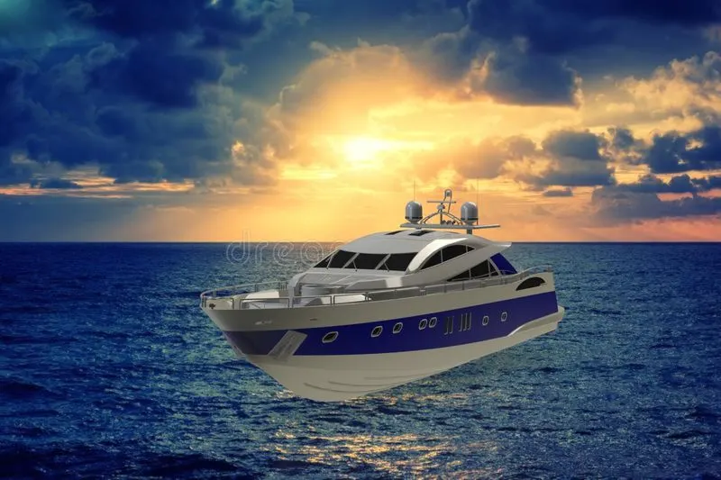
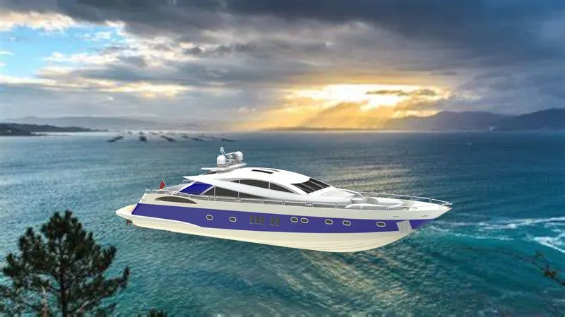
It is the another software realated to the solidworks where the tools taht combine industry leading rendering capabilities with visual desigh -oriented features and work flow, allowing easy and fast creating of visual content that communicates as design. whwre hight resolution view can be obtained.
PARTS OF YATCH ASSEMBLY
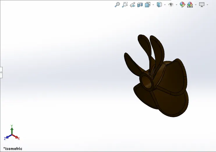
PROPELLER: It is one of the component of the yatch which is located at the back side of hull parrt which is used to move the yatch by rotaing . it is completed deeped ito the water by the help of this propellor the yatch is moved in the required direction to the ytatch there are three propellor conneted to the hull. it is sketched bye revolve feature, nad lofted boss base feature, plane is created by the referance of top plane and offset distane is given.
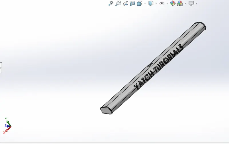
RADAR: It is located on the top of the superstructure it consists os a text names yatch tutorials its a revolve in the movement of wind flow.it is the part of yatch mode.
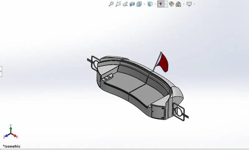
HULL: It is the base of the yatch on this hull superstructure is attached front seat,rear seat,& middle seat is aloso attached , this hull is floated on the water it is the main body of the yatch 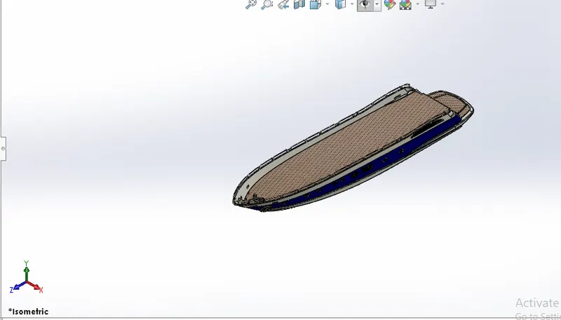
SUPERSTRUCTURE: It is the top part of the yatch model it is located on the deck surface of the hull, it acts as the covering shelter body of tge yatch,whwre the the travellers take rest inside of this superstructure. is consists of windows, doors.
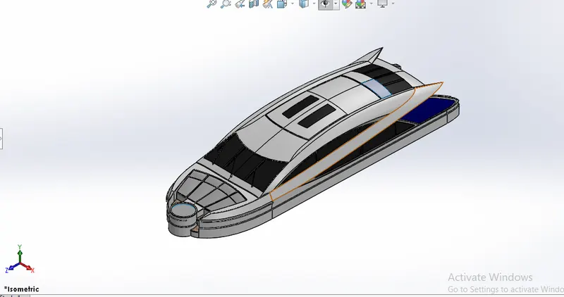
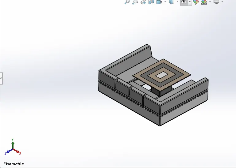
FRONT,MIDDLE & REAR SEAT OF YATCH : These are the seats of the yatch model located at diferance splace attached to the deck surface of the hull model,
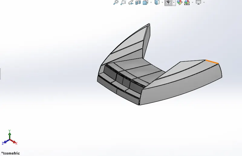
GARRAGE DOOR: It is loacted at the back side of the hull like a storage door 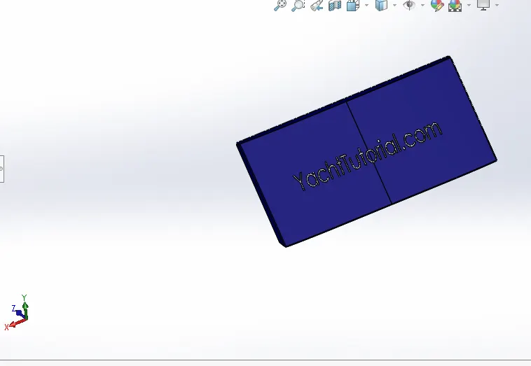
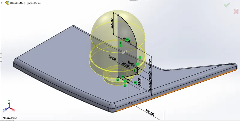
RADAR MAST : Radar mast is the electronic navigation instrument that use a rotating antena to sweep a narrow beem of miicrowaves around the water surface surrounding the ship to the horizon, detecting targets by microwavs refelected from them, generating apicturwe of the yatchs surroundings on the display screen
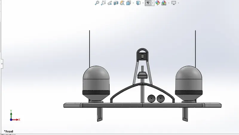
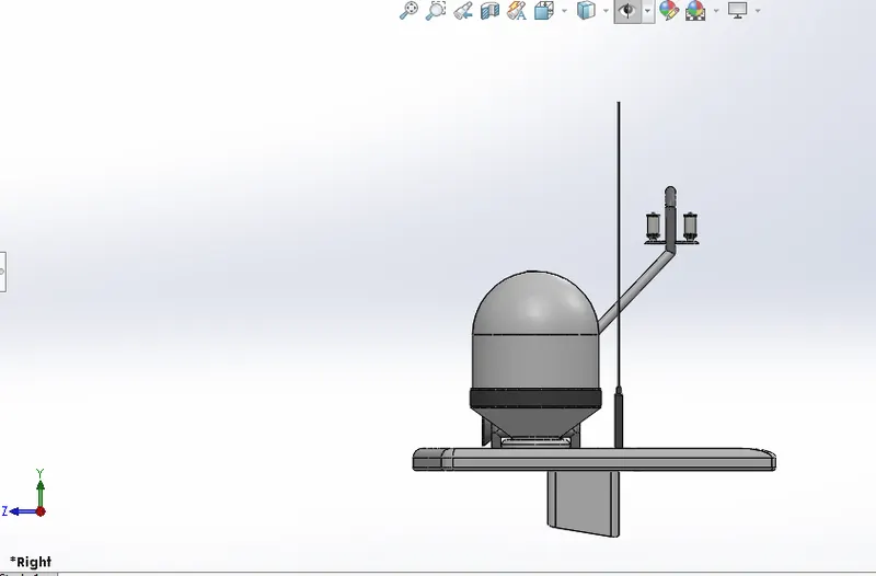

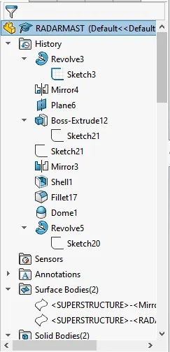
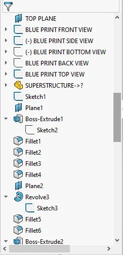
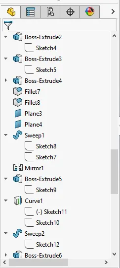
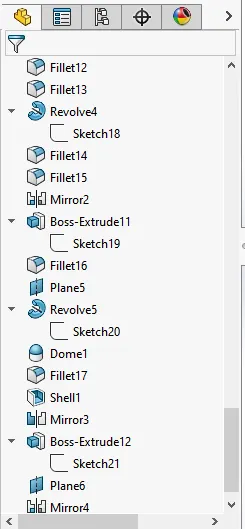
YATCH ASSEMBLY:The assemble parts of propellor, radar, hull, superstructure, seats & radar mast known as yatch assembly.by the mates & inset componet featurs this yatch assembly is assebled.
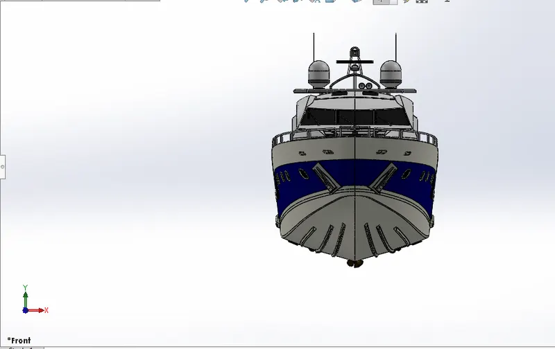
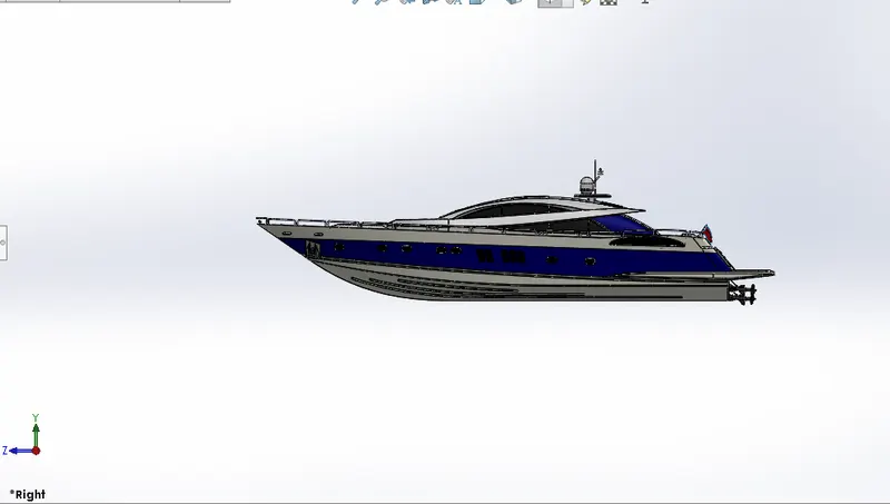
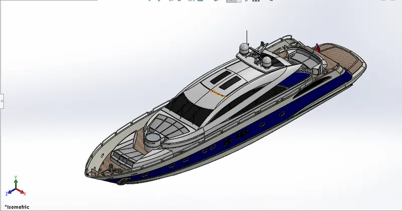
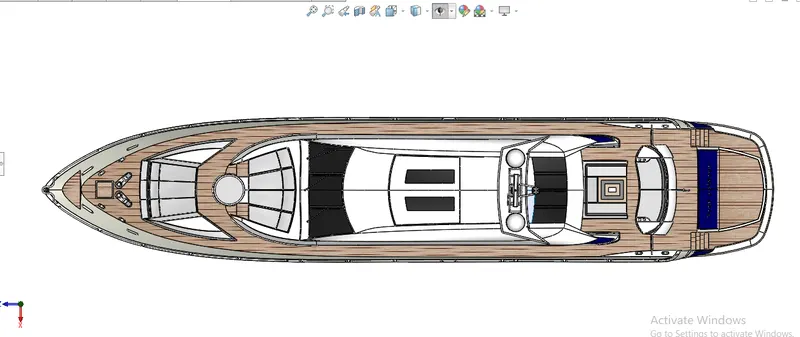
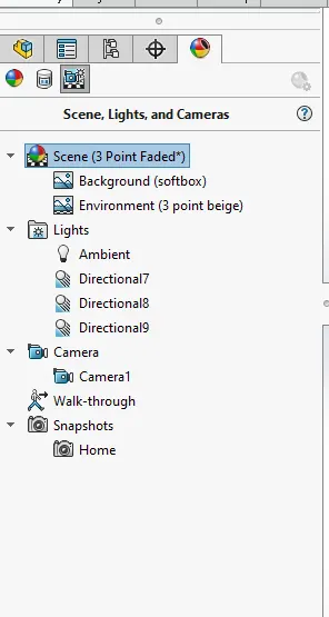
YATCH CAMERA VIEW
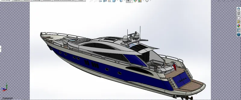
YATCH PHOTO REALSTIC 360 VIEW
VISUALIZE RENDERING VIEW IMAGES
CONCLUSION:
The parts of the yatch are modeled
The parts are inserted by the mate features , into the assembly and the complete model is assembled as yatch
The realstic image was rendred with the use of the photoview 360 and solidworks visualize.