Week 8 - Challenge 3 - Switch Bezel Design
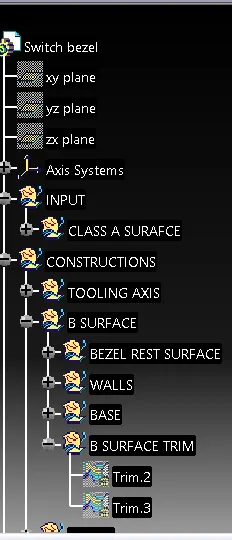
AIM -SWITH BEZEL DESIGN WITH DRAFT ANALYSIS & TOOLING AXIS
DESCRIPTION DRAFT ANALYSIS & TOOLING AXIS
To make the part to an angle dirtection. sothat the part model can be easily removed from the model cavity-core. & also acts as the guide curve to make the sweep direction in c surface at an angle of 3deg as the OEM FOLLOW.
DRAFT ANALYSIS
IT is a analysis of a plastic component to determine weather the component is actually feasible to manufacture or not mainly used for thicken the surface.at certain angle (3deg)
REQUIREMENT FOR DRAFT ANALYSIS
solid body
main tooling direction
select material mode
TOOLING AXIS CREATION
Check the correct direction that we can create the line on the class a surface
create the point at the hole as curve circle,ellipse option
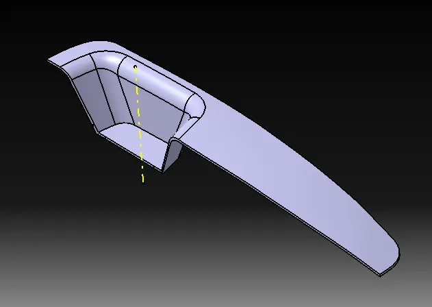
create the line of point direction through z direction & name it as a dummy tool axis change the colour, thickness & axis of the line so that we acan easily identify it.
after the creation of the tooling axis create the plane of yz referance * point ok
intersect the classa surface in to two parts
create the point to point line both side of the dummy tooling axis.with that two line create the bysecting line by selecting two line .that is the main tooling axis for draft analysis.
STEPS FOR DRAFT ANALYSIS
- switch to material mode
- activate feature draft analysis
- place the compass on main tooling direction
- activate compass logo 7 slightly move the compass over MTD line.
- set the angle & colour as per the requirement
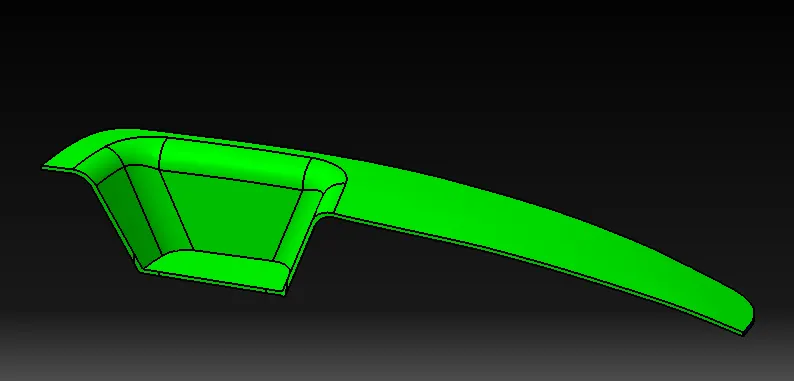
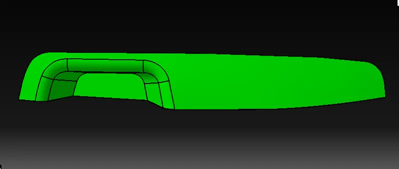
GREEN- area clear in main tooling
RED- area have no draft in main tooling
BLUE- area undercut in main tooling
- click on bodu on which draft analysis to be done
- ckeck a surface feasibility.
TYPES OF DRAFT ANALYSIS
catia v5 has two types of draft analysis
1. Quick analysis
2. Full analysis
DRAFT ANALYSIS-is used to make the part thicken by the class A,B& C SURFACES at required dimensions.
TOOLING AXIS- it is used to sweep the surface at required direction as draft direction referance element.
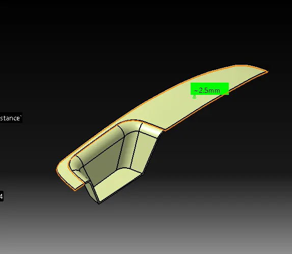
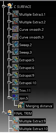
RESULT Join the classs a & class c surface & trim it with b surface so that the 2.5 mm of thickness surface is obtained after thet check the boundry of the part its should not dorm it is correct if it formed there are some open edges check it and compleyte the part.
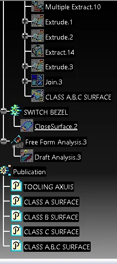
Define part body apply closs surface solid body is obtained.
Define it in part body and ckeck the boundry line weather it is in close surface or not.after that change the part design & add the close surface now the solid class c surface is obtained.
DRAFT ANALYSIS & TOOLING AXIS.
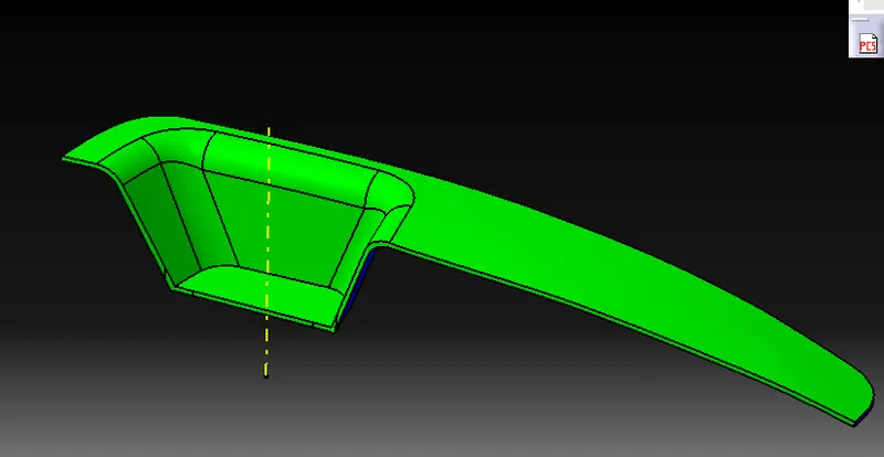
THICKNESS OF COMPONENT 2.5 MM