Roof challenge
ROOF PANEL DESIGN
Car roof panel positioned at the car upward most part, covers the drivers and passengers from the atmosphere conditions and protects them from fatalities in case of a roll over crash. Likewise, other automobile components the aesthetics and the safety together are incorporated in its design.Spanning from the A-pillar to the D- pillar, the windshield, center lighting, back door of the car are mounted on the roof panel.
Safety point of view vehicle roof plays very crucial role specially roll over kind of accidents, in which vehicle tips over onto its side of roof. And vehicle rollover crashes are the causes of many fatalities and several head, neck and spine trauma around the world. Therefore passenger safety is also very important parameter in front of OEM’s. It is not only a marketing strategy but also it is a obligation stipulated by international standards that are now place in several countries, as well as a governmental requirement.
DESIGN CONSIDERATIONS:
- Structural rigidity
- Head room clearance
- Visibility criteria
- Snow load criterion
DESIGNING OF ROOF PANEL AND COMPONENTS:
The master section is kept as the reference to develop the components so in order not to deviate from the primary considerations and functionalities.
The components of the roof top panel are:
- Front roof rail.
- Bow roof.
- Reinforcement roof center.
- Rear roof rail.
Front roof rail:
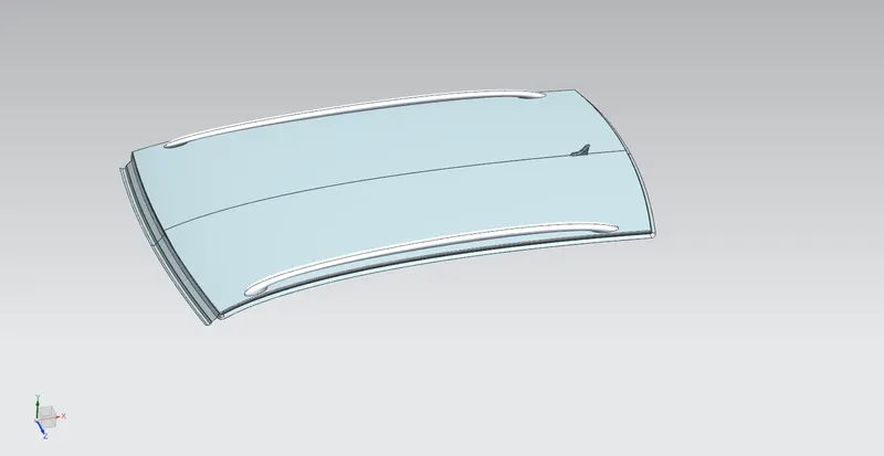
From the above design, the surface needed is extracted
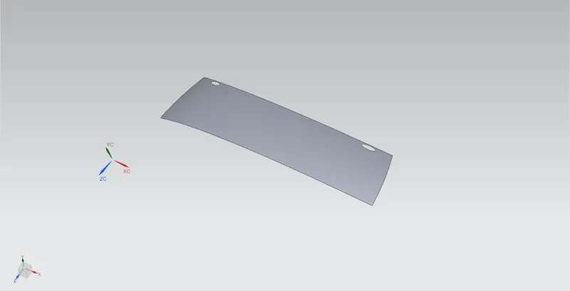
It is then untrimmed, and the master section is followed to develop the front roof rail, the master section is as follows:
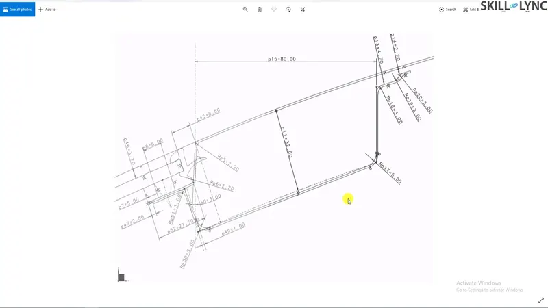
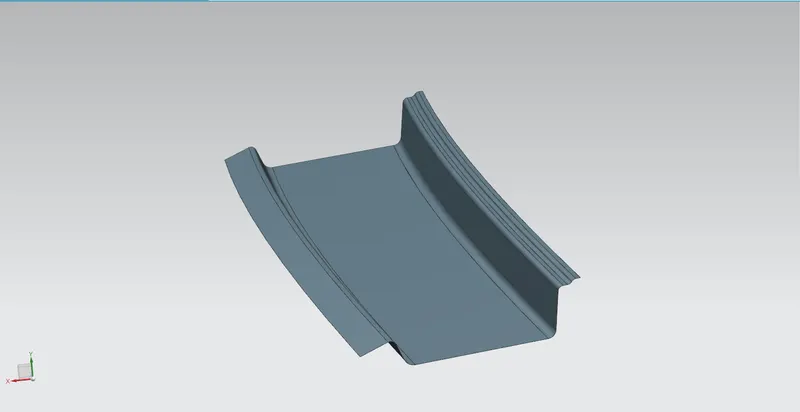
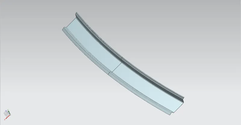
The draft analysis for the same is then carried out to ensure its manufacturability along the tooling direction.Then the geometry is mirrored and sewed.
Bow roof rail:
The same extracted surface is used to develop the master section and then the reilef features, mastic points are incorporated into the design. Mastic sealants are an effective and economical way to seal the air, dust and other micro particles intervention.
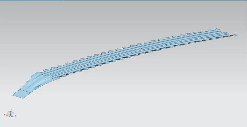
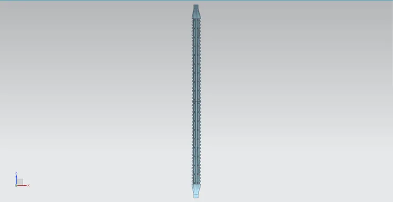
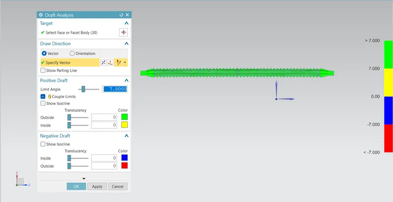
The draft analysis when carried out for the bow roof rail
Center roof rail
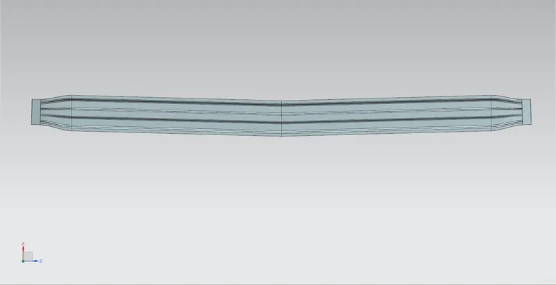
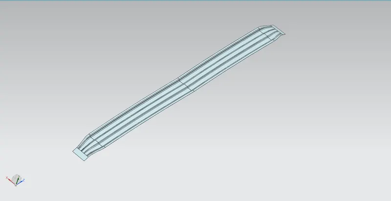
Reinforcement roof center
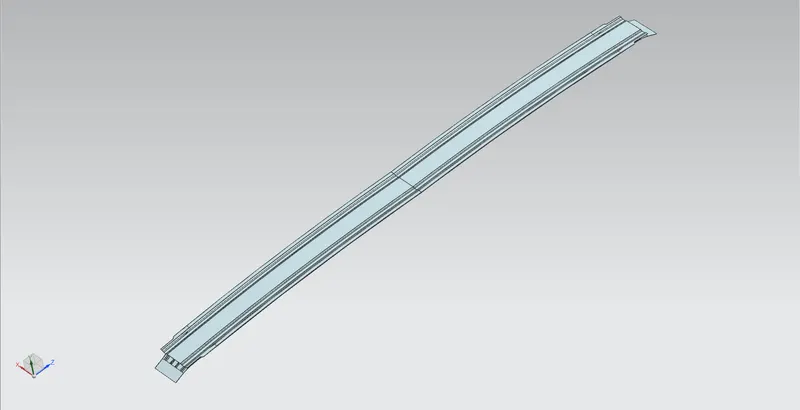
Rear roof rail:
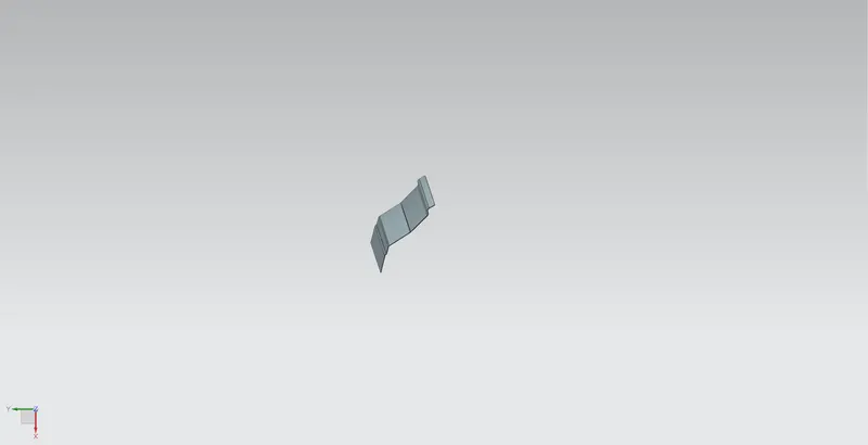
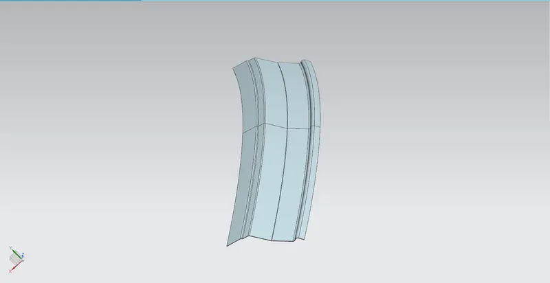
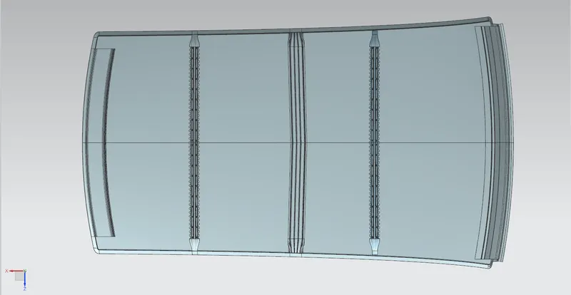
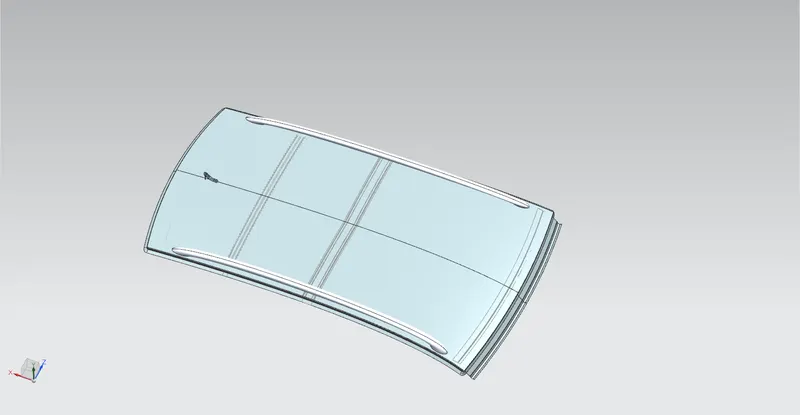
ROOF TOP DESIGN:
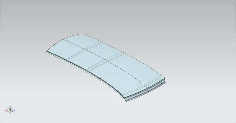
HEAT DISTORTION AND SNOW LOAD CRITERIA:
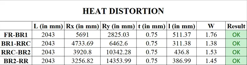
The heat distortion and the snow load are the two general predictive calculations beforehand to the structural and conditional analysis. The panel is segemented along its components and then the curvature is taken for the calculations as follows in both conditions.
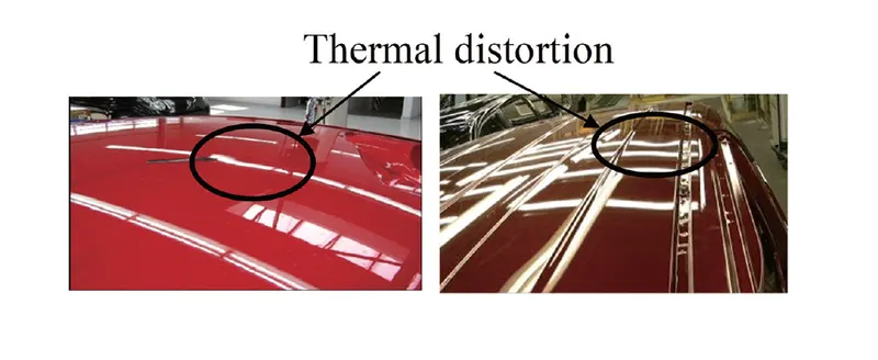
The temperatures of shell materials such as the roof panel and side frame outers easily increase because they are thin, but temperatures of inner plates and thick reinforcements do not increase sufficiently. Therefore, deformation restriction in the width direction of the vehicle body is strong and deformation of the roof panel is larger in the up and down direction of the body. Thermal distortion is often seen at the center and ends of panels as local deformation and the deformation volume is small at approximately 0.1 to 0.2 mm, so focal point check is performed to determine the extent of the deformation
Heat distortion:
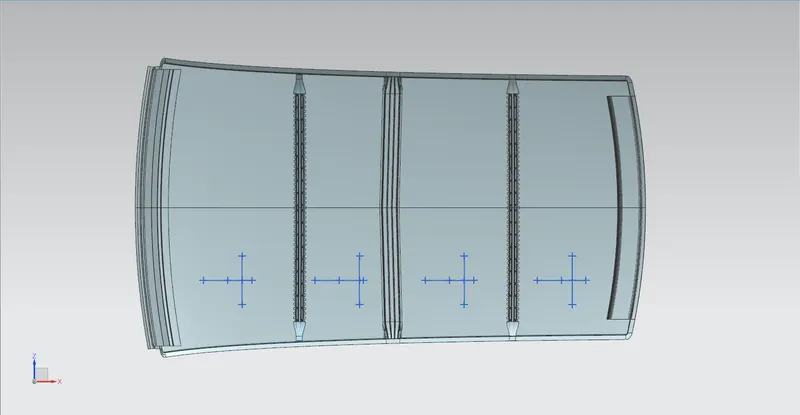
The -3Y is drawn and a 100mm up and downward lines are drawn to obtain the below image depicted curvature.
The governing equation is,
`W = [1.73 x 10^(-3) x L] + [1.85 x 10^(-8) x (R^2)/t] + [ 1.10x10^(-3) x l] - 2.68`
where,
L = Roof Length in X-Direction[mm](Roof dimension in 0-Y)
R = Roof curvature
R = 2(Rx*Ry)/(Rx+Ry)
Rx = X curvature
Ry = Y curvature
t = Roof plate thickness [mm]
l = Bow Roof Span [mm]
The governing condition being : Judgement Condition : OK< 2.7> 3.1
Snow load criteria:
The mid section is taken as reference and the upward and downward lines are created to obtain the curvature data.
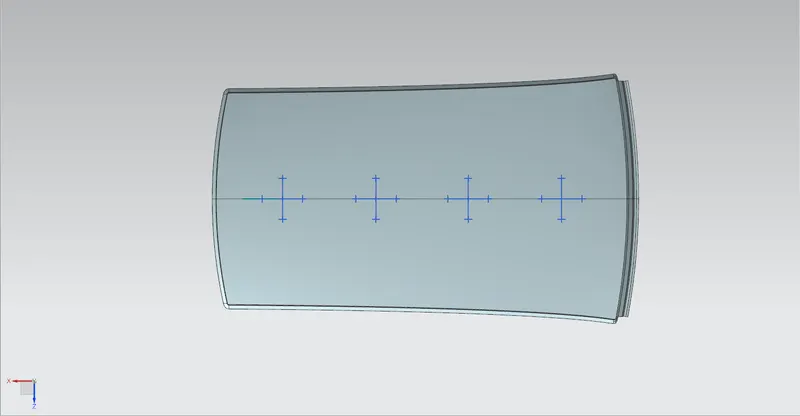
The governing equation is
`Qr = [Iy x t2] / [α x s x [(Rx + Ry)/2]2 x 10-8]`
where,
`α = My x Lx2 x 10-12 , My = Y(Ly-Y)`
Judgement condition = Qr ≥ 3.1
t = Roof plate thickness [mm]
Ly = Distance between the front and rear roof Rails on the Vehicle along with 0Y[mm]
Length of Roof panel with the center point between Roof rail Front /Rear as the front and rear reference point.
Lx = Distance between the Left and Right end of the roof on the Roof BOW [mm]
Width of the roof panel exposed on the surface.
Y = Distance front Front Roof Rail to Roof BOW[mm]
s = Distance for which Roof BOW bears divided load [mm]
`s = L1/2 + L2/2`
Iy = Geometrical moment of inertia of Roof BOW (Y cross-section )[mm4]
Rx = Lateral direction curvature radius of roof panel Y cross-section on Roof BOW [mm]
Roof panel curvature Radius of the Length Lx in Front view
Ry = Longitudinal Direction curvature radius of the Roof panel X cross-section on Roof BOW [mm]
Roof panel X curvature radius of length s in Side view

To conclude, the failure to meet the specifications of the criteria is moved ahead with working along the styling team, to possibly make the curvature study in the failure segments and rework to improve the curvature to pass the basic conditions.
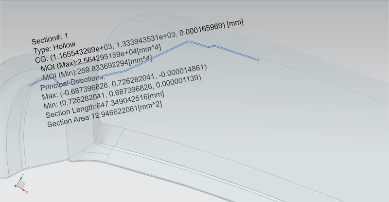
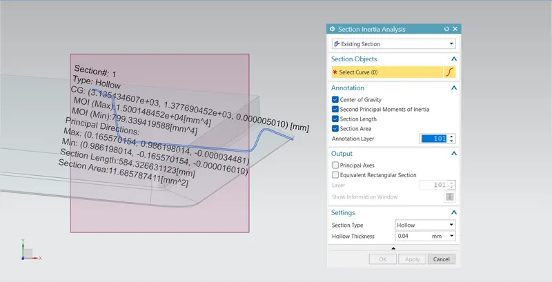
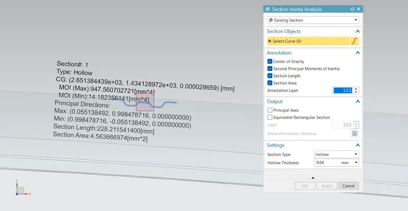
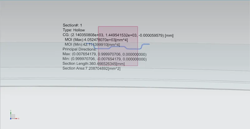
SECTION INERTIA 0-Y:
Front roof rail
Bow roof
Reinforcement roof center
Rear roof rail