Roof challenge
ROOF DESIGN
Design of car roof, it's ditch area and neccecary reinforcements.
DEFINITION-

A car roof is the portion of an automobile that is above the passenger compartment, protecting the vehicle occupants from sun, wind, rain, and other external elements.
It also plays vital role in positioning the wind shield glass and carrying lights with the help of its various reiforcement rails.
Roof with side pillars gives the dual tone look to a car. Type of roof in automobiles are-
- Convertible roofs.
- Hardtops.
- Sunroofs.
- T-tops.
- Targa tops.
- Vinyl roofs.
COMPONENTS-
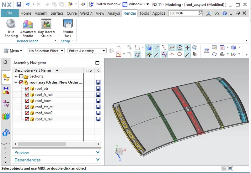
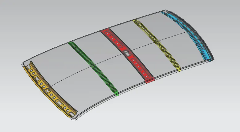
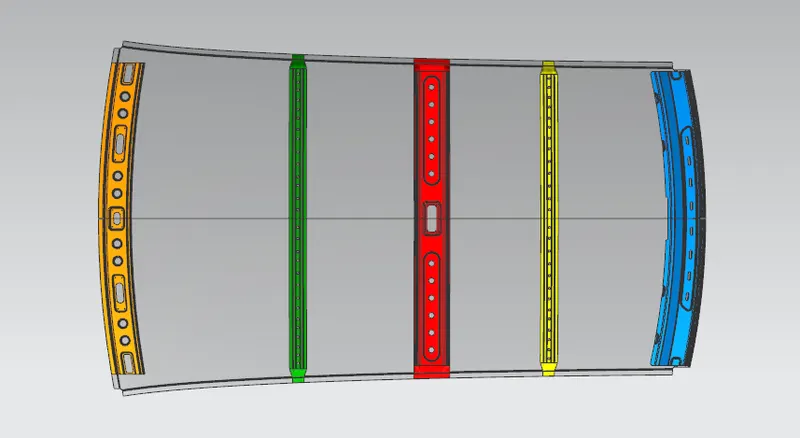
Roof of a vehicle can not be just the outer roof as it is visible from outside, because in that case the roof will not be able to withstand the snow load or side load during a crash. That is why the reinforcement in the form of front, center, rear rails and bow roofs are provided in order to improve it's strength. These reinforcemnets are of 0.75 mm thick and joined to the outer roof by mastics and spot welds.
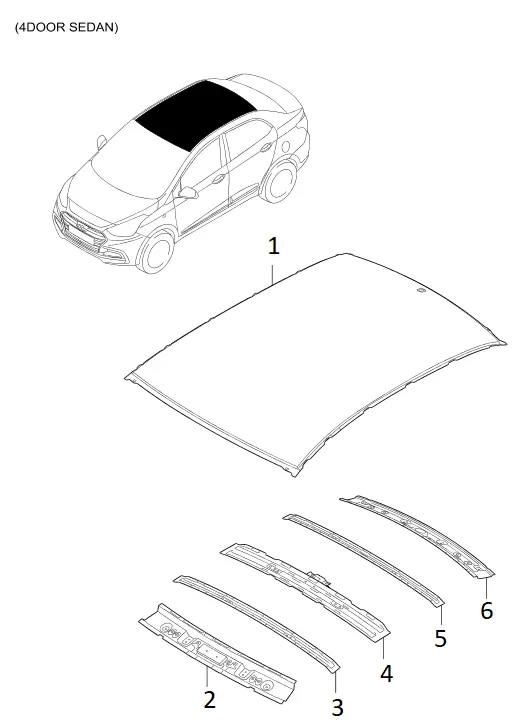
1. Outer Roof- This is the styling part visible from outside. OEM'S manufacture outer roof within their facilities.
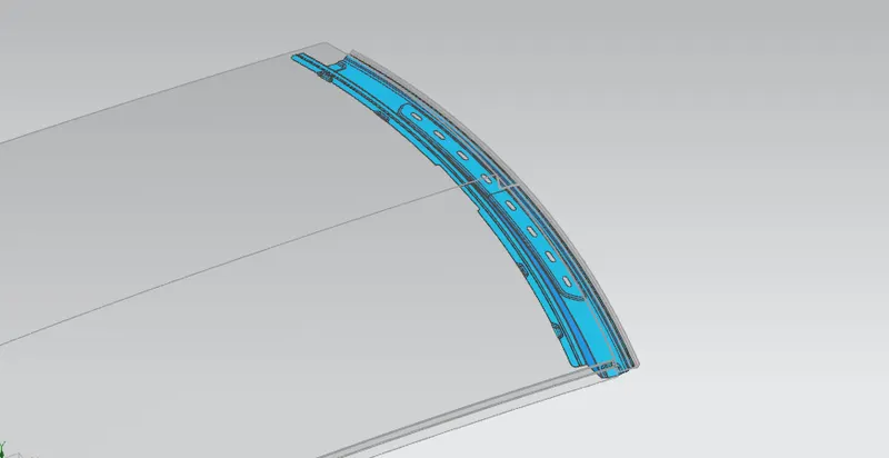
2. Front Roof Rail- It is the reiforcement member which present at the front side of roof and plays a vital role in positioning and holding of winsheild.
3. First Bow Roof- It is the reiforcement member small in size about 60- 80 mm wide but provides necessary stiffness for the roof and improves the load bearing capacity of the roof. positioning of which decides by curvature study. Bow roofs attach to the roof with mastics in middle and by spot weld at the ends to maintain the aesthatics.
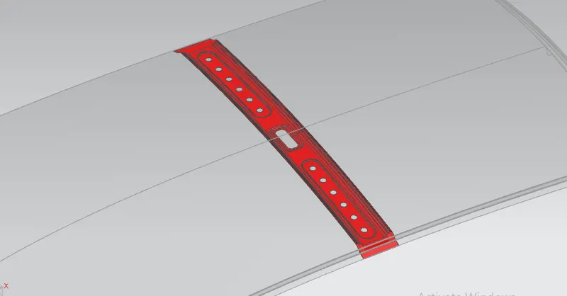
4. Center Roof Rail- This reinforcement is present in middle region of the roof which is wider than normal bow roofs. In some cases roof rail center also provide holding for the light mount and one bow roof beneath it.
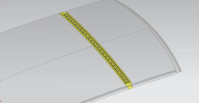
5. Second Bow Roof- It is the same bow roof member whihc provides the stiffness to the later half part of the roof. Number of bow roofs depends on the length of the roof. longer the roof ,more strength will be provided to the structure.
6. Rear Roof Rail- It is the rear reinforcement which is present at rear side of the roof.
CONSIDERATIONS-
1. Visibility Criteria.
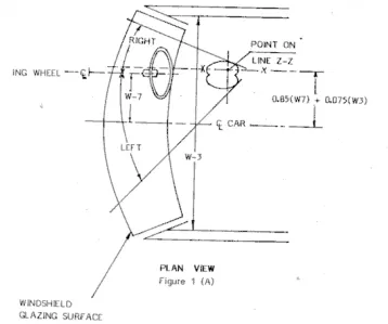
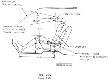
2. Head clearance.
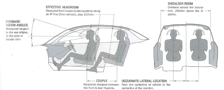
3.Curvature study
DESIGN OF ROOF AND REINFORCEMENTS USING NX CAD
Given-
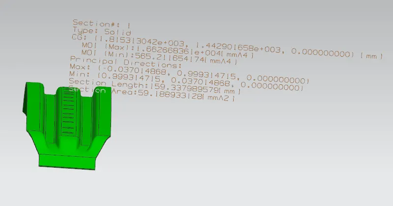
1. Master section of ditch area of roof and front rail.
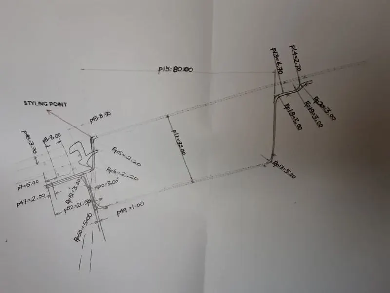
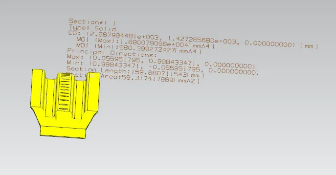
2. Master section of ditch area of roof and rear rail.
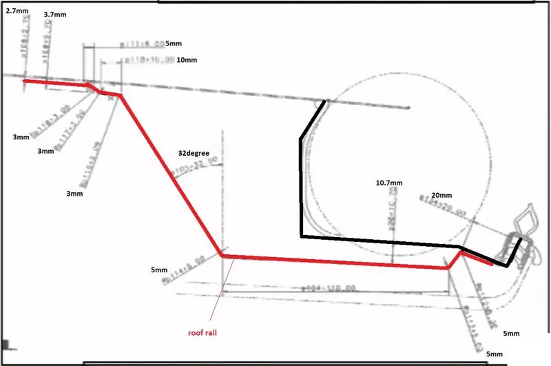
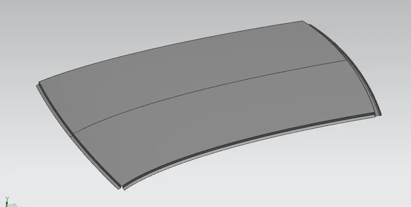
1. CREATE OUTER ROOF AND DITCH AREA AS PER MASTER SECTION.
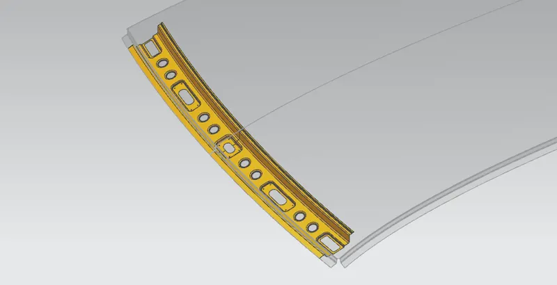
2. CREATE FRONT RAIL REINFORCEMENT USING MASTER SECTION.
3. CREATE BOW ROOF RAIL FIRST AND JOIN IT WITH SIDE DITCH AREA.
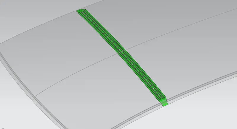
4. CREATE REIFORCEMENT CENTER AND JOIN IT WITH SIDE DITCH AREA.
5. CREATE BOW ROOF RAIL SECOND AND JOIN IT WITH SIDE DITCH AREA.
6. CREATE FRONT RAIL REINFORCEMENT USING MASTER SECTION
DRAFT ANALYSIS
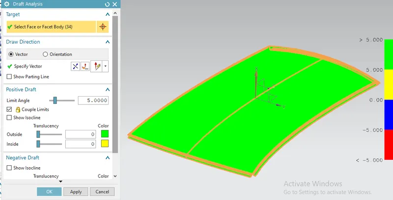
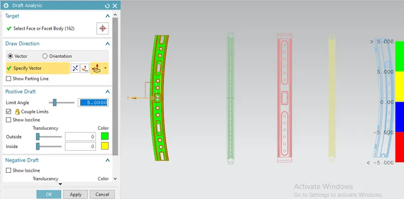
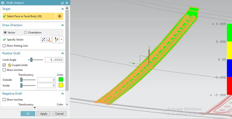
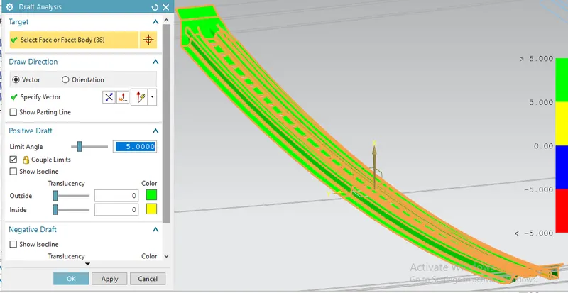
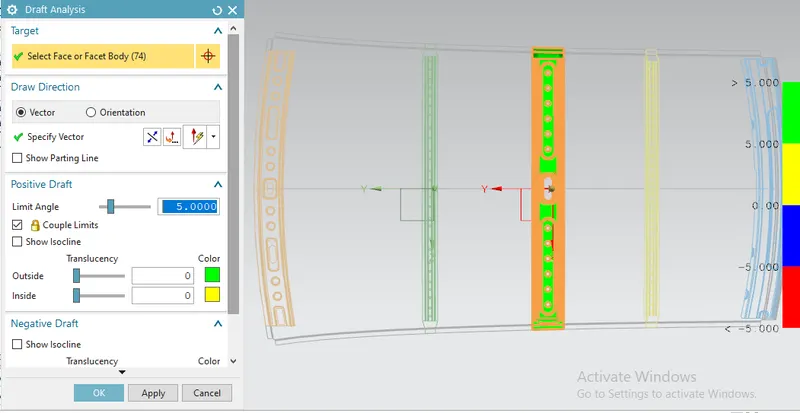
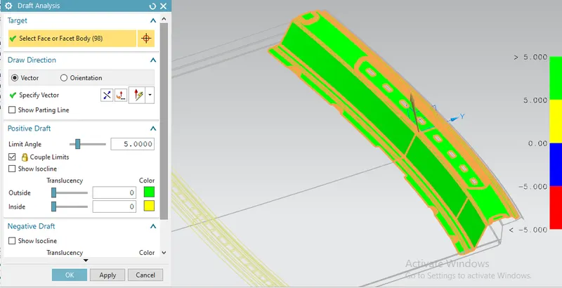
Draft analysis is lies in green zone which makes the part drawable during manufacturing.
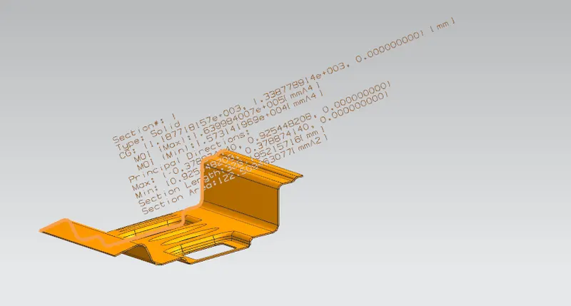
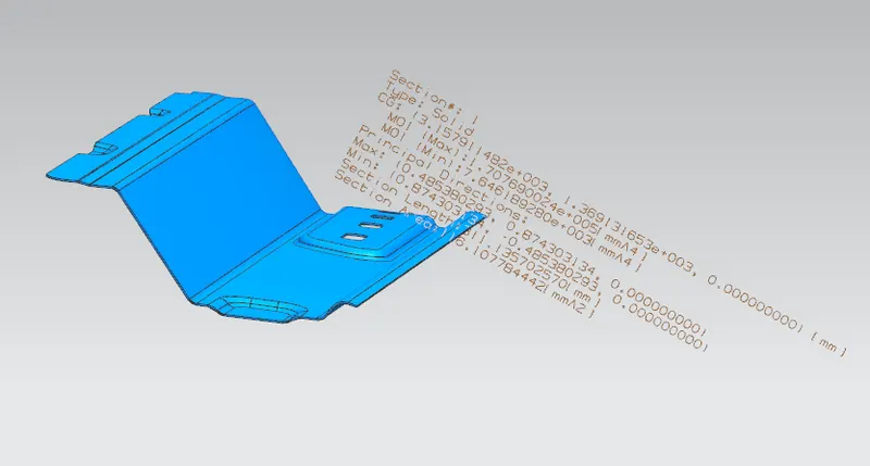
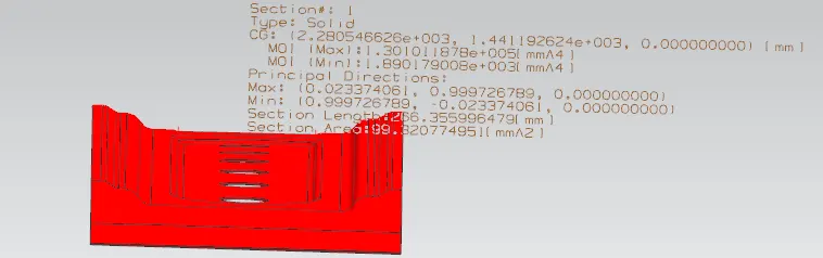
SECTION INERTIA ANALYSIS
CURVATURE STUDY
HEAT DISTORTION CALCULATION
W = [1.73 x 10^(-3) x L] + [1.85 x 10^(-8) x (R^2)/t] + [ 1.10x10^(-3) x l] - 2.68
Judgement Condition : OK< 2.7> 3.1
L = Roof Length in X-Direction[mm](Roof dimension in 0-Y)
R = Roof curvature = 2(Rx*Ry)/(Rx+Ry)
Rx = X curvature
Ry = Y curvature
t = Roof plate thickness [mm]
l = Bow Roof Span [mm]
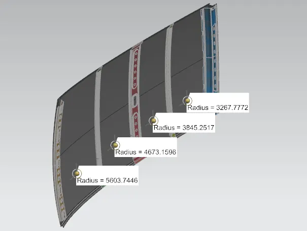
1. Create sketch to determine the curavature Rx and Ry of the surface at -3Y axis.
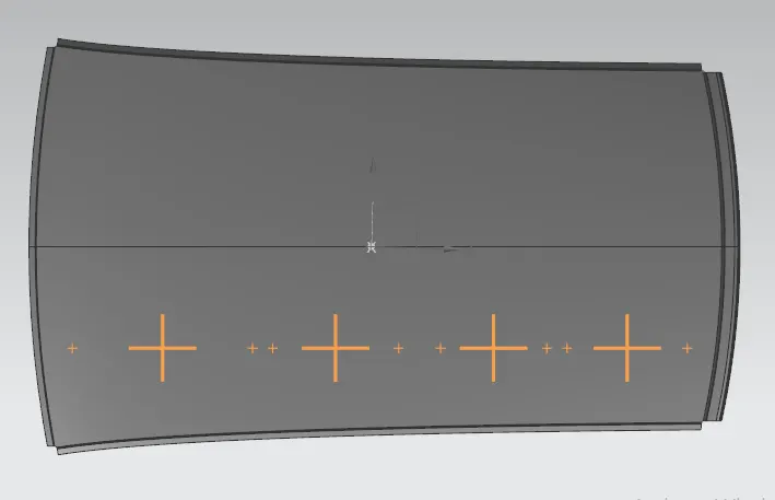
Rx curvature
Ry curvature
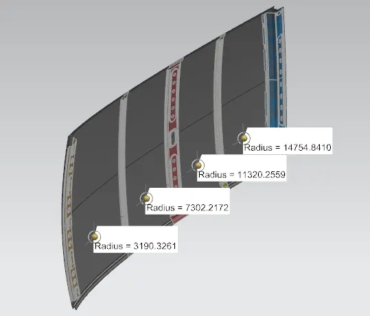
Use these values to determine W.

SNOWED CONDITION CALCULATION.
Qr = [Iy x t2] / [α x s x [(Rx + Ry)/2]2 x 10-8]
α = My x Lx2 x 10-12 , My = Y(Ly-Y)
Judgement condition = Qr ≥ 3.1
t = Roof plate thickness [mm]
Ly = Distance between the front and rear roof Rails on the Vehicle along with 0Y[mm], Length of Roof panel with the center point between Roof rail Front /Rear as the front and rear reference point.
Lx = Distance between the Left and Right end of the roof on the Roof BOW [mm]Width of the roof panel exposed on the surface.
Y = Distance front Front Roof Rail to Roof BOW[mm]
s = Distance for which Roof BOW bears divided load [mm] , s = L1/2 + L2/2
Iy = Geometrical moment of inertia of Roof BOW (Y cross-section )[mm4]
Rx = Lateral direction curvature radius of roof panel Y cross-section on Roof BOW [mm],Roof panel curvature Radius of the Length Lx in Front view.
Ry = Longitudinal Direction curvature radius of the Roof panel X cross-section on Roof BOW [mm], Roof panel X curvature radius of length s in Side view.
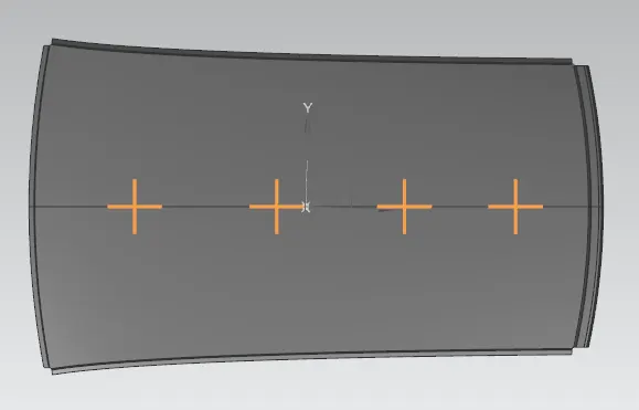
2. Create sketch to determine the curavature Rx and Ry of the surface at 0Y axis.
Rx curvature
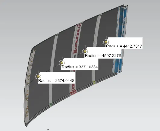
Ry curvature
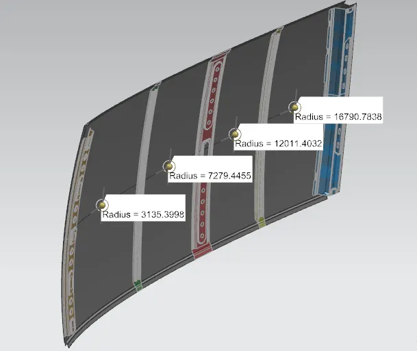
use these values to determine Qr.

RESULT- For this model surface curvature satisfies the heat distortion and snow load criteria in this curvature study,
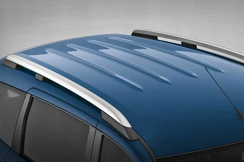
but in case it does not satisfy the curvature study additional embosses can be provided to the roof of the car in order to improve the strength so that it can withstand the external loads like below-
FINAL DESIGN-
.