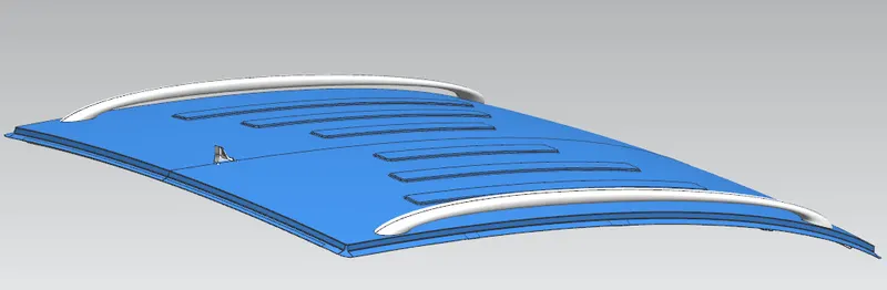
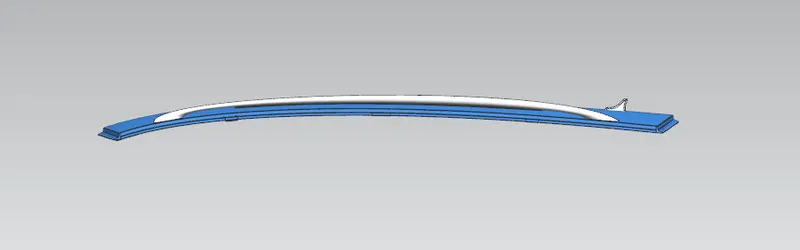
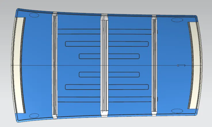
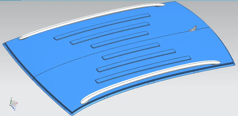
Roof challenge
AIM : To design and development of the CAR Roof with its component by following the Mastersection & design parameters :-
- To develop the essential Flanges, Reinforcement with appropriate dimensions by using stylling Roof as input data.
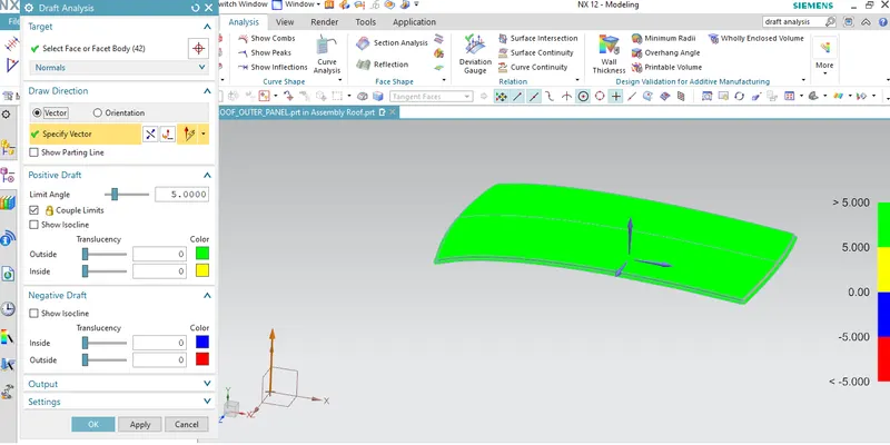
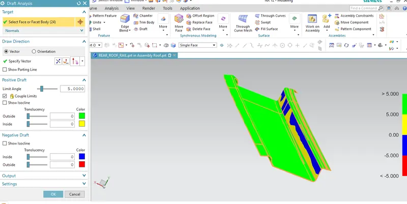
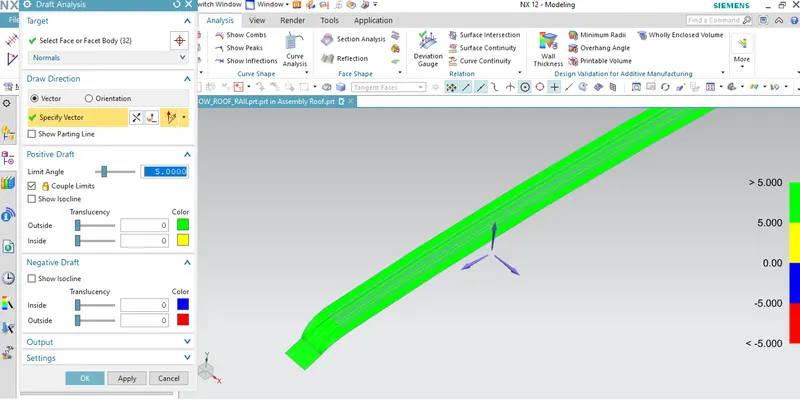
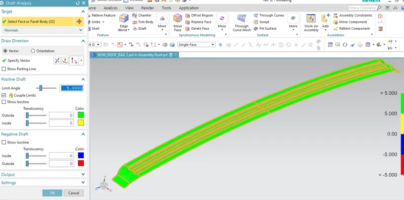
- To check Draft Analysis of the design designed surface.
- To find Section Modulus of the components.
- To determine Heat Distortion criteria of car's Roof.
- To determine Snow Load criteria of car's Roof.
INTRODUCTION
The Roof is the portion of an Automobile that sits above the passanger compartment which protect the occupants from sun, wind, rain and injury during Car-crash.
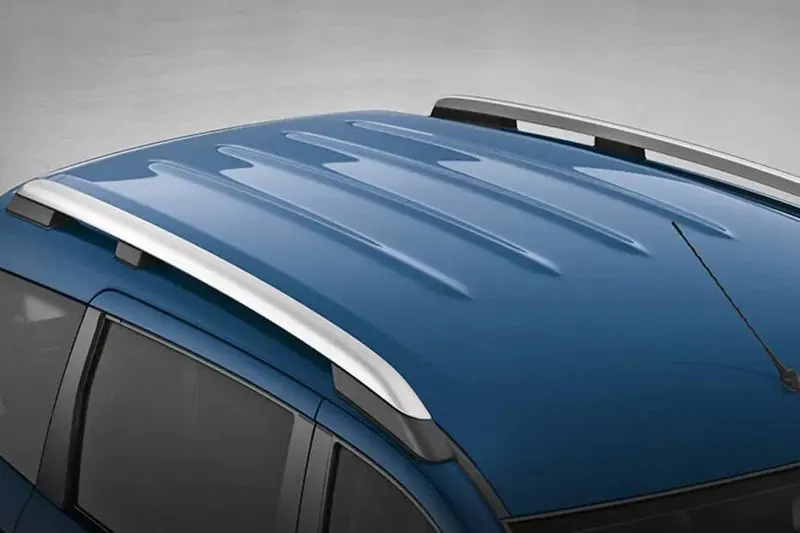
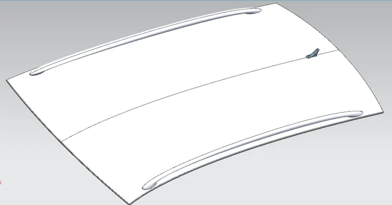
Given Input data
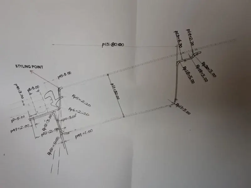
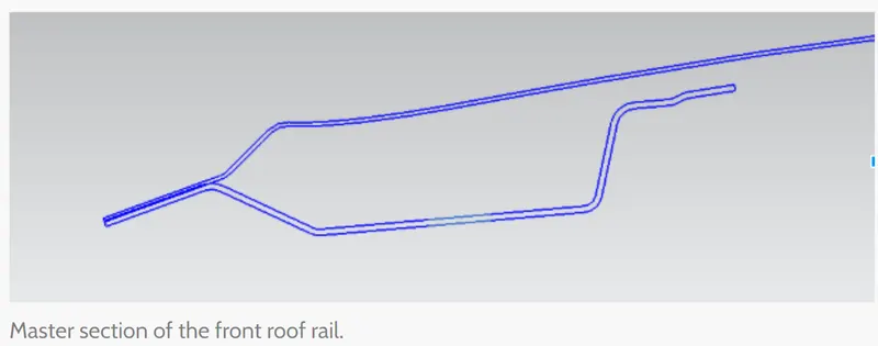
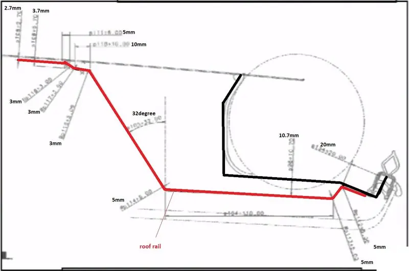
(Front Roof Rail master section reference image)
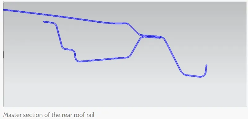
(Rear Roof rail master section reference image)
PROCEDURE
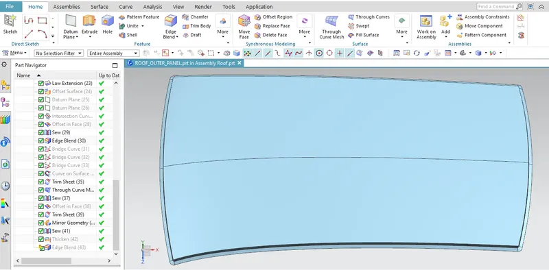
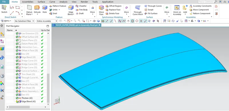
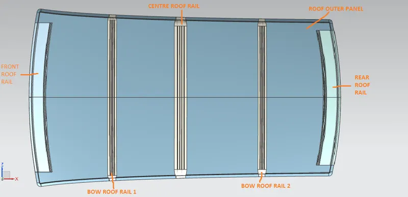
ROOF OUTER PANEL
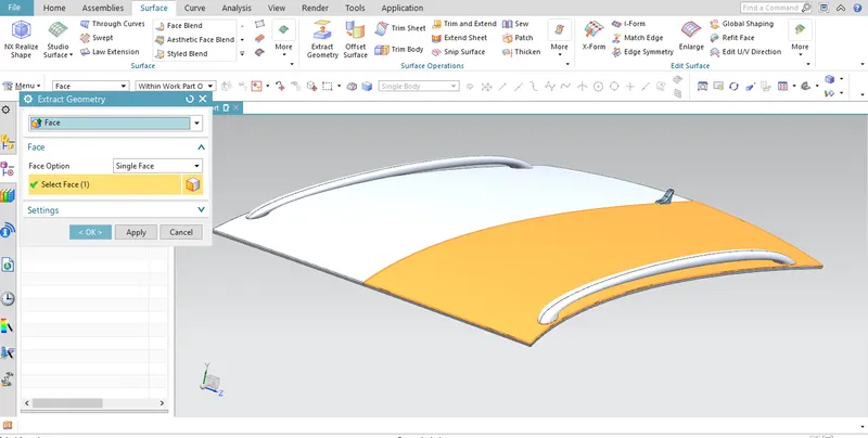
- EXTRACT the half surface of input.
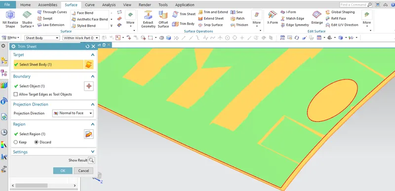
- UNTRIM the surface and then TRIM the sheet by using Extracted surface.
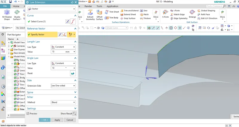
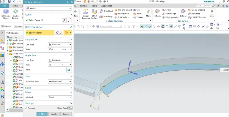
- To get the desired surface; use Commands - LAW EXTENSION, OFFSET SURFACE, DATUM PLANE, INTERSECTION CURVE, OFFSET CURVE in Face, TRIM SHEET, BRIDGE CURVES, THROUGH CURVES and at the corners apply STUDIO SURFACE or THROUGH CURVE MESH .
- Apply EDGE BLEND, MIRROR GEOMETRY , SEW
- Apply the Thickness = 0.75 mm
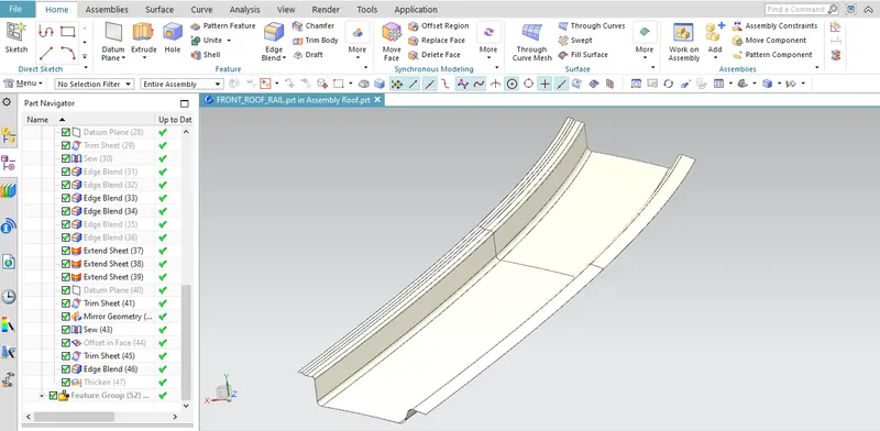
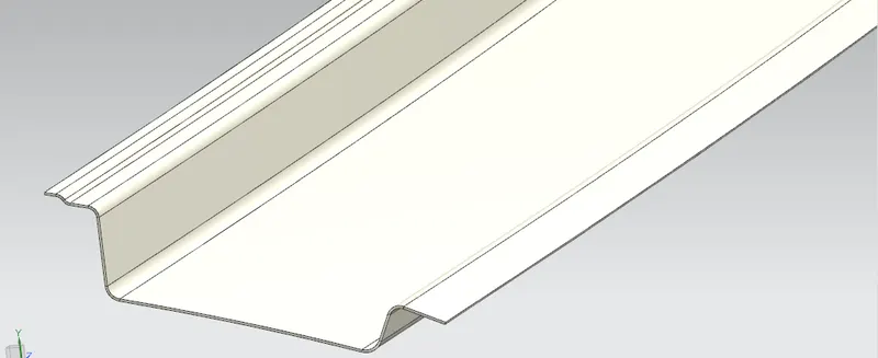
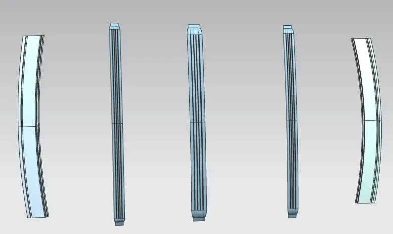
FRONT ROOF RAIL
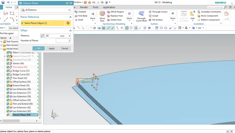
This is the reinforcement provided at the front and this part joined the BIW body and windshield. It is fixed to BIW with spot welds and roof surface is attached with the help of Mastic seals.
- Create Datum plane and offset this plane at 80mm distance.
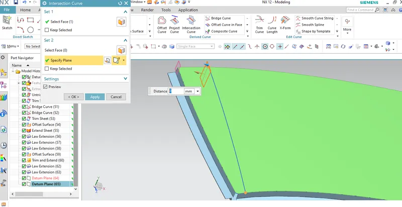
- Use INTERSECTION Curve at this datum plane.
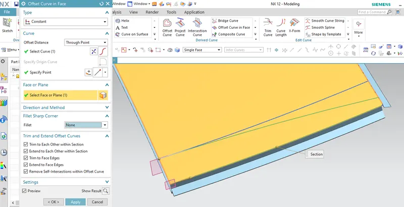
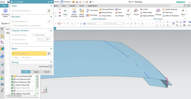
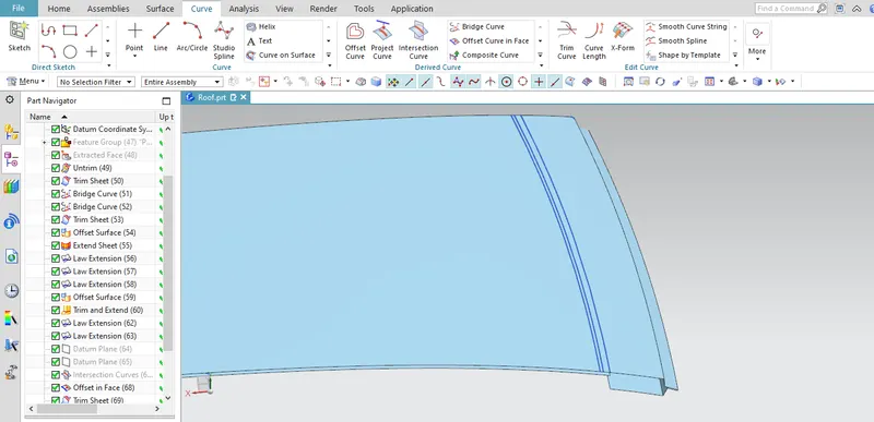
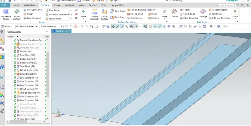
- OFFSET the surface as Mastersection; 1st surface = (4.7+0.75+0.75)mm , 2nd surface = (2.7+0.75+0.75)mm & now TRIM these sheet using offseted curves curves.
- Use the appropriate commands to get desired surface according to the given Master-Section.
- Apply Thickness = 0.75 mm.
Similarly,
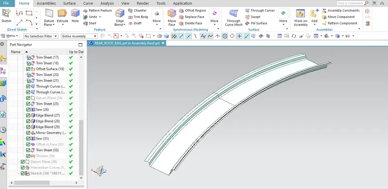
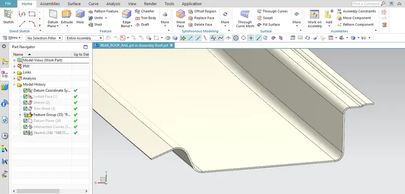
REAR ROOF RAIL
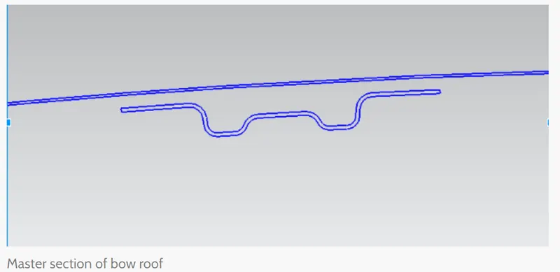
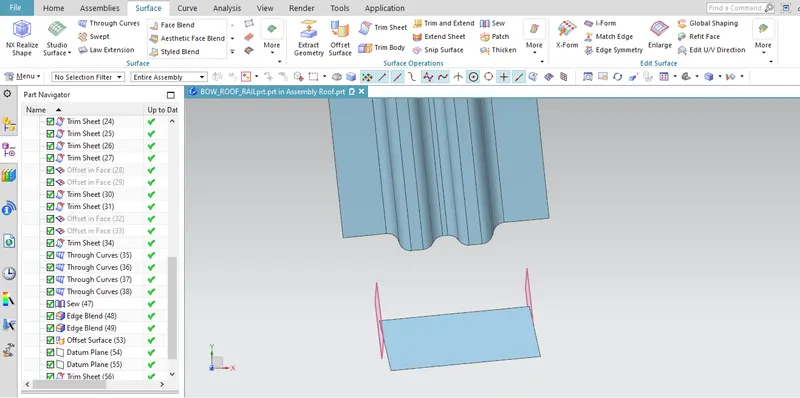
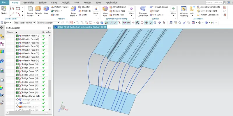
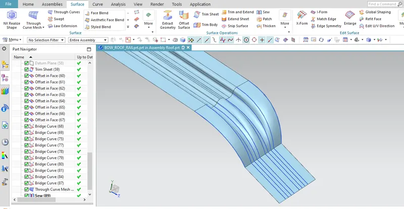
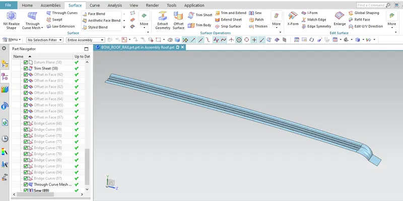
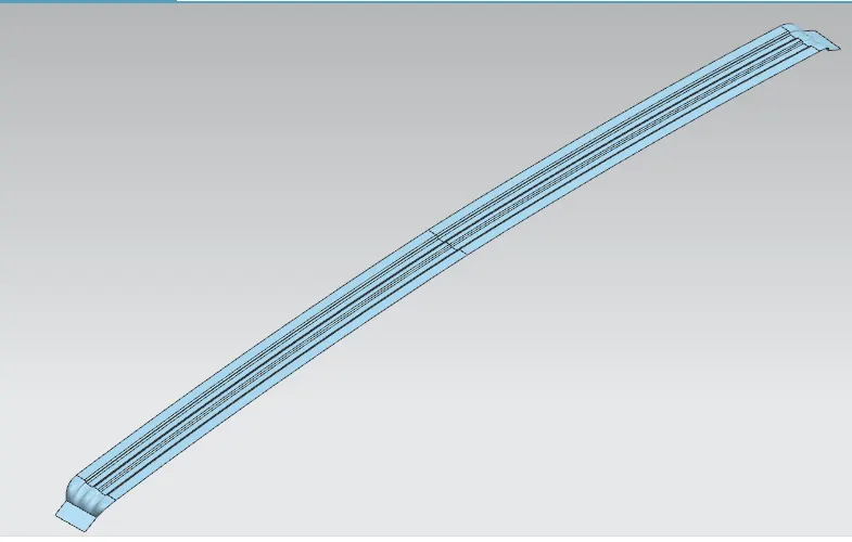
BOW ROOF RAIL 1
It is the additional reinforcement provided to increase the strength of roof. It is fixed with the roof body along with mastic seal.
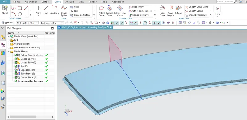
- create the DATUM Plane at 23-25% Arc length & INTERSECT with the surface.
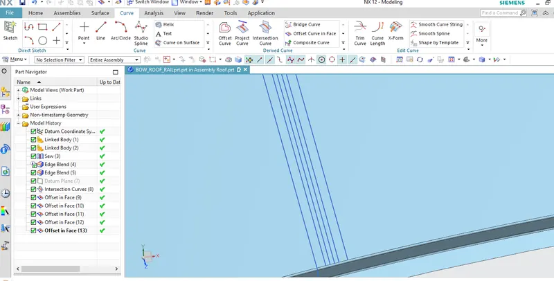
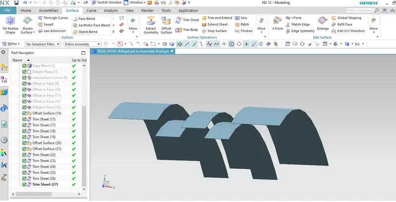
- OFFSET CURVES on the surface as req. & also OFFSET SURFACE in downward having clearance = 5mm with outer Roof panel.
- Make the BOW Roof Rail's width = 60mm
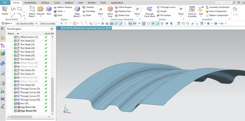
- TRIM the surface using the curves & then use ThROUGH CURVES to join the surfce together.
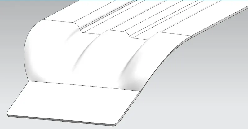
- in the Flange side, OFFSET the Flange single surface & Trim appropriately by creating Datum plane.
- use OFFSET Curve in Face in Trimmed surface & Join this with BOW rail using BRIDGE CURVE - THROUGH CURVE MESH
- now, SEW the surfaces & apply MIRROR Geometry
- apply EDGE BLENDS, Thickness = 0.75 mm
Similarly
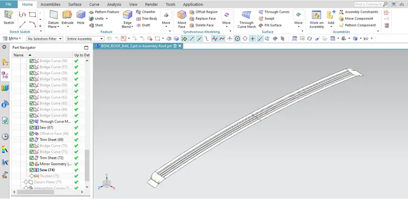
BOW ROOF RAIL - 2
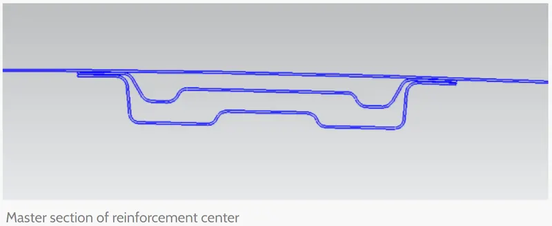
CENTRE ROOF RAIL
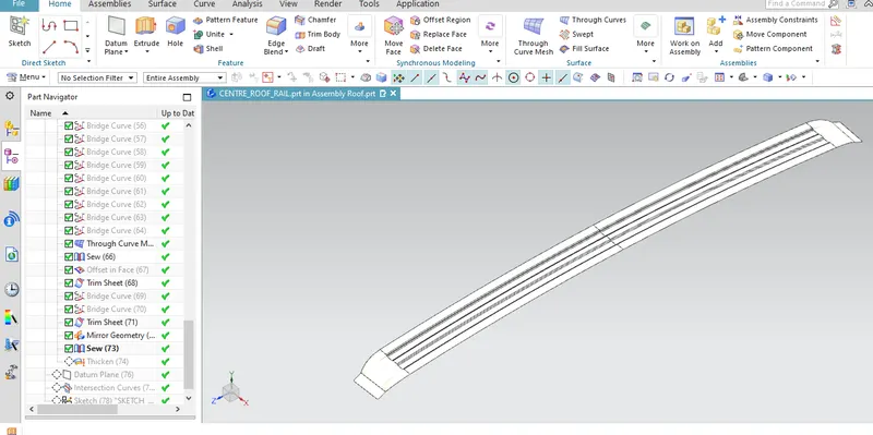
Centre Roof Rail can be considered as reinforcement which joins the Left & Right part of the Roof. It is fixed with Roof by Mastic sealants and BIW by spot weld.
- use above commands as given Mastersection.
- make the centre Rail's width = 80mm
- Thickness = 0.75 mm
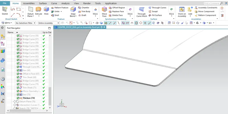
SURFACE VIEWS
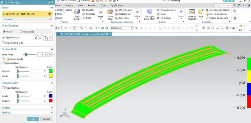
DRAFT ANALYSIS
ROOF OUTER PANEL
FRONT ROOF RAIL
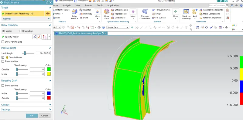
(The Blue patches on the surface is not considerable because it is showing negative draft, and we have to modify the surface)
REAR ROOF RAIL
BOW ROOF RAIL 1
BOW ROOF RAIL 2
CENTRE ROOF RAIL
SECTION MODULUS Calculation
S = I/Y
S = Section Modulus
I = moment of inertia
Y = distance from nuetral axis to top/bottom fiber = H/2
FRONT ROOF RAIL
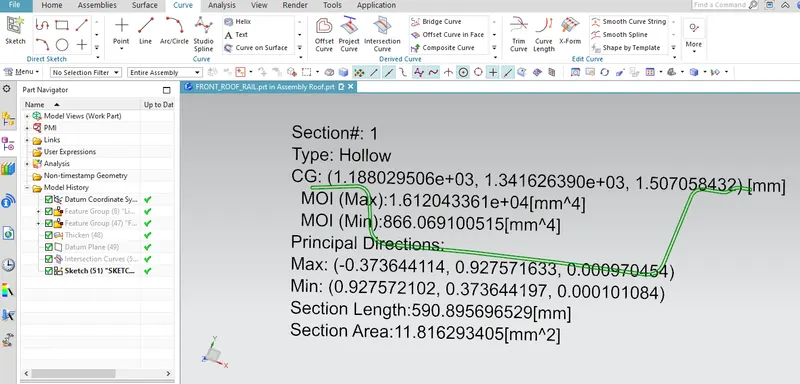
I (max) = 1.612 *10^4 (mm^4)
I (min) = 866.069 (mm^4)
Y = 123.47/2 = 61.73 (mm)
S = I/Y
S = (1.612*10^4)/61.73 = 261.13 (mm^3) - maximum
S = (866.69)/61.73 = 14.04 (mm^3) - minimum
REAR ROOF RAIL
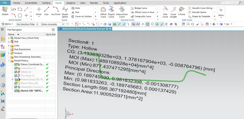
I (max) = 1.489 *10^4 (mm^4)
I (min) = 877.437 (mm^4)
Y = 118/2 = 59 (mm)
S = I/Y
S = (1.489*10^4)/59 = 252.37 (mm^3) - maximum
S = (877.437)/59 = 14.87 (mm^3) - minimum
BOW ROOF RAIL 1
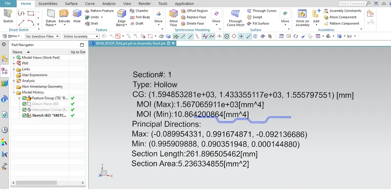
I (max) = 1.567 *10^3 (mm^4)
I (min) = 10.864 (mm^4)
Y = 60.54/2 = 30.27 (mm)
S = I/Y
S = (1.567*10^3)/30.27 = 51.76 (mm^3) - maximum
S = (10.864)/30.27 = 0.358 (mm^3) - minimum
BOW ROOF RAIL 2
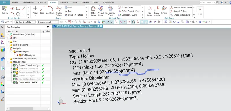
I (max) = 1.561 *10^3 (mm^4)
I (min) = 14.038 (mm^4)
Y = 60/2 = 30 (mm)
S = I/Y
S = (1.561*10^3)/30 = 52 (mm^3) - maximum
S = (14.038)/30 = 0.467 (mm^3) - minimum
CENTRE ROOF RAIL
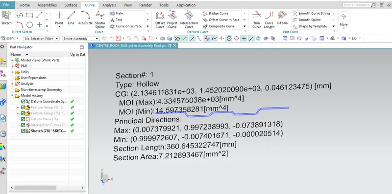
I (max) = 4.334 *10^3 (mm^4)
I (min) = 14.597 (mm^4)
Y = 85/2 = 42.5 (mm)
S = I/Y
S = (4.334*10^3)/42.5 = 101.97 (mm^3) - maximum
S = (14.597)/42.5 = 0.343 (mm^3) - minimum
HEAT DISTORTION CURVATURE CALCULATIONS
Heat Distortion study plan is an important role in sheet metal usage. Heat Distortion temperature is a temperature limit above which the material cannot be used for structural applications. In this study we predict the heat distortion temperature at which material starts soften when exposed to a fixed Load at elevated temperature. In order to avoid the bending/damages on the Roof during Loading; the study will predict the BOW Roof position on the roof to strengthen it.
Bow–Roof prediction Formula
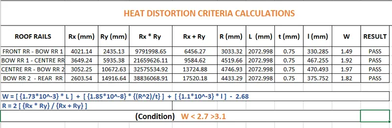
W = [1.73 x 10^(-3) x L] + [1.85 x 10^(-8) x (R^2)/t] + [ 1.10x10^(-3) x l] - 2.68
Judgement Condition : W< 2.7> 3.1
Where
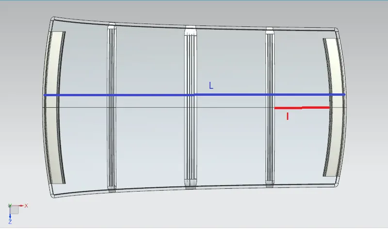
L = Roof Length in X-Direction[mm](Roof dimension in 0-Y)
R = Roof curvature
R = 2(Rx*Ry)/(Rx+Ry)
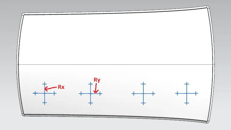
Rx = X curvature
Ry = Y curvature
t = Roof plate thickness [mm]
l = Bow Roof Span [mm]
PROCEDURE
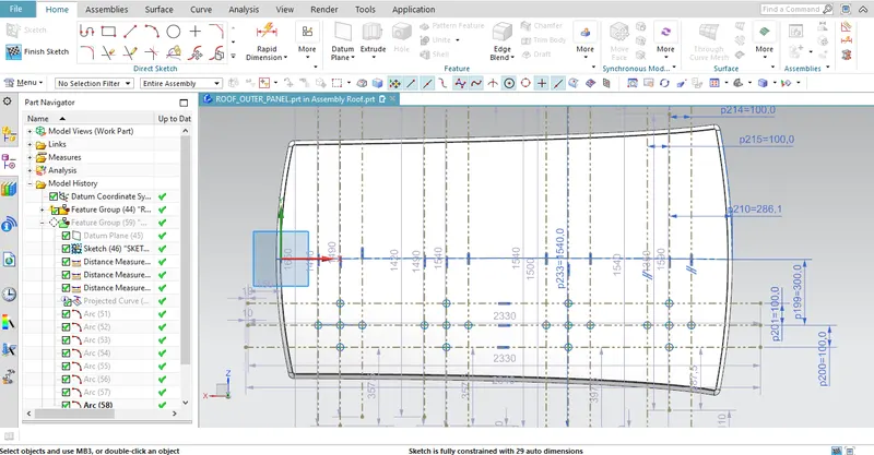
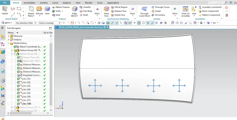
- Create a Datum plane on the roof outer panel & create sketch.
- create a horizontal line at the middle & make a OFFSET = 300mm, and from this offseted line; make offset = 100mm in both up-down side. It gives three Horizontal lines.
- measure distance between the roof rails and Bow rails.; make a vertical line at the middle and also offset =100 mm in both left-right direction. It also gives 3 vertical lines.
- create the POINT at the intersection of these lines.
- make all the lines as reference line.
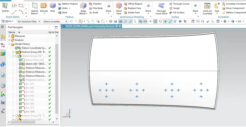
- Finish sketch & use Project curves on the surface.
- using these projected points, create ARC by command Three point Arc
- measure the ARC by Local radius command.
- at last, make calculations
CONCLUSION
Our designed surface passes all the condition of Heat Distortion Criteria.
SNOW LOAD CRITERIA CALCULATION
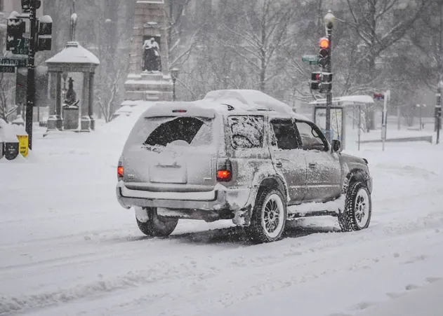
This calculation is done in Cold regions where snow occurs. so, the Roof design is such a wat that it has to pass through these calculations to ensure that our designed surface has sufficient stiffness to withstand at load due to deposition of snow over the Roof.
PROCEDURE
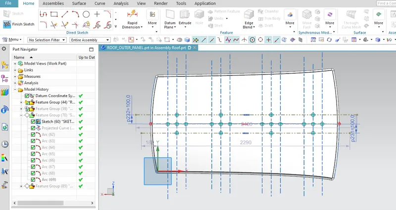
- Create a Datum plane on the roof outer panel & create sketch.
- create a horizontal line at the middle & make offset = 100mm in both up-down direction. It gives three Horizontal lines.
- measure distance between the roof rails and Bow rails.; make a vertical line at the middle and also offset =100 mm in both left-right direction. It also gives 3 vertical lines.
- create the POINT at the intersection of these lines.
- make all the lines as reference line.
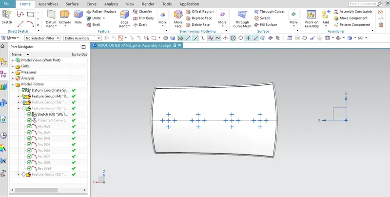
- Finish sketch & use Project curves on the surface.
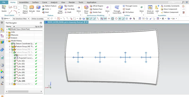
- using these projected points, create ARC by command Three point Arc
- measure the ARC by Local radius command.
- at last, make calculations
Snow load Prediction formula
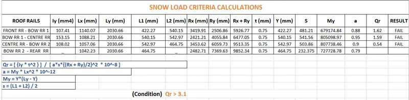
Qr = [Iy x t2] / [α x s x [(Rx + Ry)/2]2 x 10-8]
Note: The Qr value given over here is correct. There was a typo error in the formula given in the video.
Where
α = My x Lx2 x 10-12 , My = Y(Ly-Y)
Judgement condition = Qr ≥ 3.1
250 ≤ s ≤ 380
t = Roof plate thickness [mm]
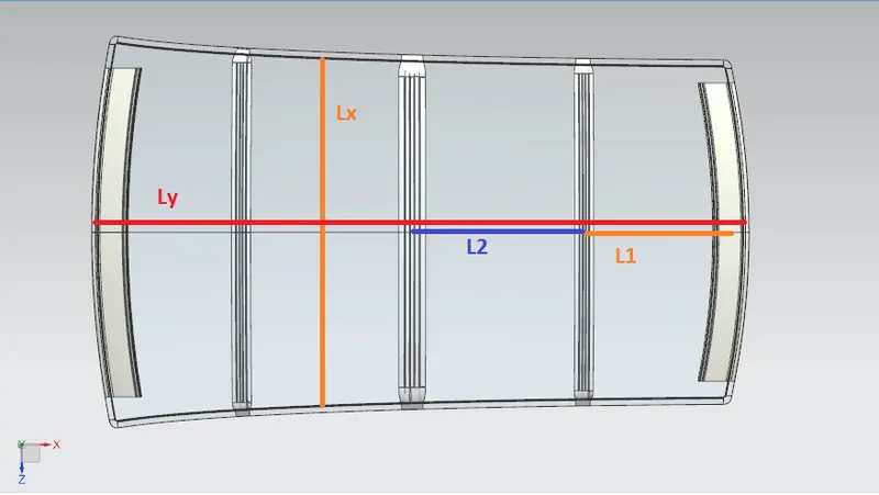
Ly = Distance between the front and rear roof Rails on the Vehicle along with 0Y[mm]
Length of Roof panel with the center point between Roof rail Front /Rear as the front and rear reference point.
Lx = Distance between the Left and Right end of the roof on the Roof BOW [mm]
Width of the roof panel exposed on the surface.
Y = Distance front Front Roof Rail to Roof BOW[mm]
s = Distance for which Roof BOW bears divided load [mm]
s = L1/2 + L2/2
Iy = Geometrical moment of inertia of Roof BOW (Y cross-section )[mm4]
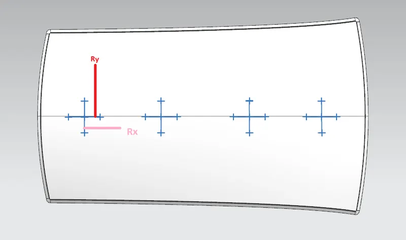
Rx = Lateral direction curvature radius of roof panel Y cross-section on Roof BOW [mm]
Roof panel curvature Radius of the Length Lx in Front view
Ry = Longitudinal Direction curvature radius of the Roof panel X cross-section on Roof BOW [mm]
Roof panel X curvature radius of length s in Side view
PROCEDURE
CONCLUSION
From the Calculation, we can identify that surface is failed on the Snow Load Criteria. ie; our Roof designed surface is not strength/stiff enough to bear the Snow Load.
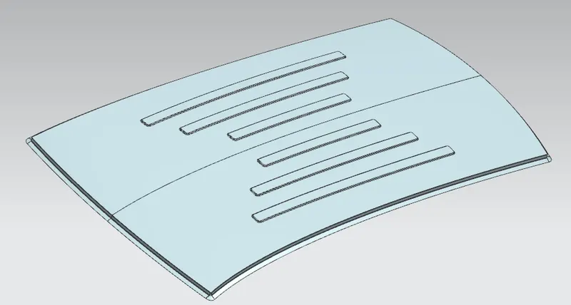
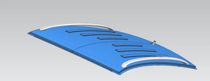
To Increase the strength of ROOF, we provide the EMBOSSES over the surface.
DIFFERENT VIEWS
\