Roof challenge
ROOF DESIGN
AIM
- To design the roof for the given styling surface with essential flanges and reinforcements and to analyse the design for draft analysis and section inertia analysis.
- To determine the position of the bow roof by doing the curvature study on the roof and performing necessary calculations.
Introduction
Roof:
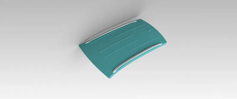
- An automobile roof or car top is the portion of an automobile that sits above the passenger compartment, protecting the vehicle occupants from sun, wind, rain, and other external elements. The roof is generally designed in curve for better strength and stability.
- Reinforcements like Front roof rail(RRR), Bow roofs(BR), Centre Roof Reinforcement (CRR) and Rear Roof Rail(RRR) are provided to increase the roof strength and rigidity.
- Hard tops, sunroof, convertibles are the main types of car tops.
- Today, sunroofs, moonroofs, panoramic roofs or targa tops are widely available on most new vehicles, each offering something in between a fixed roof and a full convertible.
- The front roof rail joins the roof panel with the windshield glass and the side body panel. It also accompanies the brackets map lamp and room lamp mountings.
- The rear roof rail joins the roof panel with back door hinge and body side panel of the car.
- The bow roofs are positioned in the most flat surface of the roof panel.
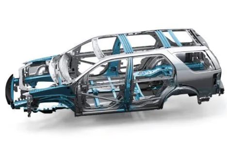
Design Methodology
Considerations:
- Thickness of the roof panel - 0.75mm
- Thickness of reinforcements - 0.75mm
- With tool opening angle of 3°.
- Provided with minimum fillet radius of 3mm.
Other standard data for design:
- Providing optimum clearance for windshield mounting using rubber mounts and adhesives in the front portion of roof.
- Considering the front visibility criteria and head impact zone to obtain optimum depth and length of FRR.
- Necessary clearance has to be provided for headliner or trim.
- Considering the rear visibility criteria and passengers head room clearance for Rear roof and bow roofs design.
- Mastic points to join reinforcements with roof.
Roof design:
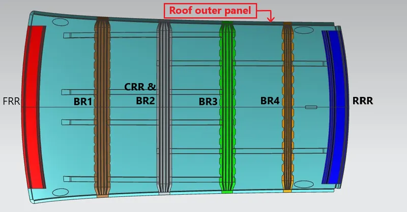
Fig shows: Roof design with reinforcements
Roof outer panel:
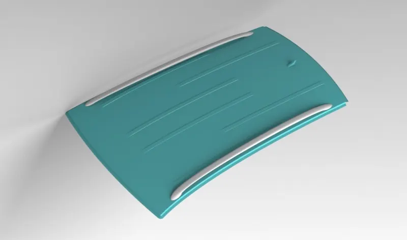
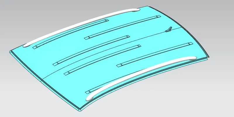
- The outer panel is the exposed part of the roof to the environment. Hence it has a Class-A surface finish and its aerodynamic design improves the aesthetic look and performance of the car.
- From the input styling surface the ditch area is designed providing flanges at front, side and rear edges.
- An opening tool angle of 3 degree is provided.
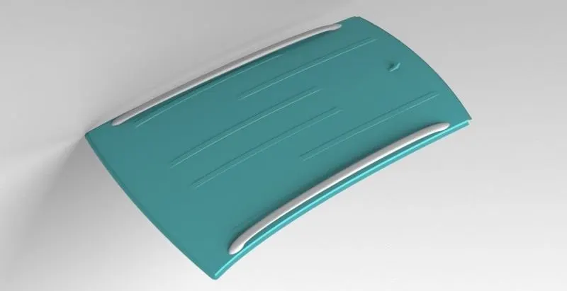
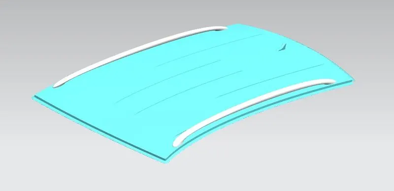
- Necessary embosses have been provided for stylish look and to improve the strength.
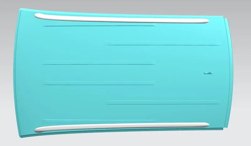
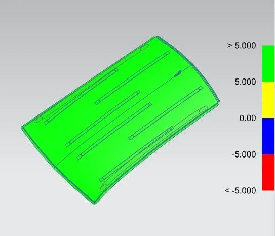
- Draft analysis of roof outer panel is done with minimum of 5 degree.
Front Roof Rail:
- Front roof rail is one of the reinforcements provided for the outer panel which joins the windshield glass with outer panel and body side panel.
- It is designed based on the master section provided.
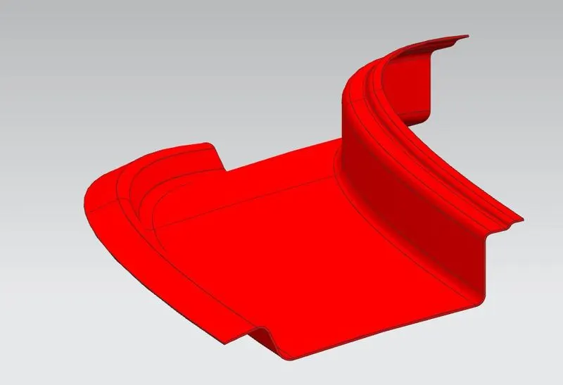
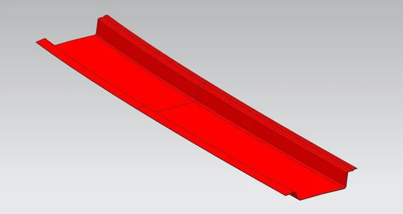
Master section provided-
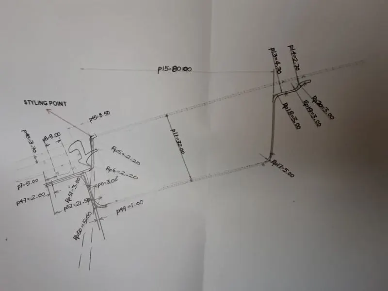
Fig shows: Master section of Front Roof Rail
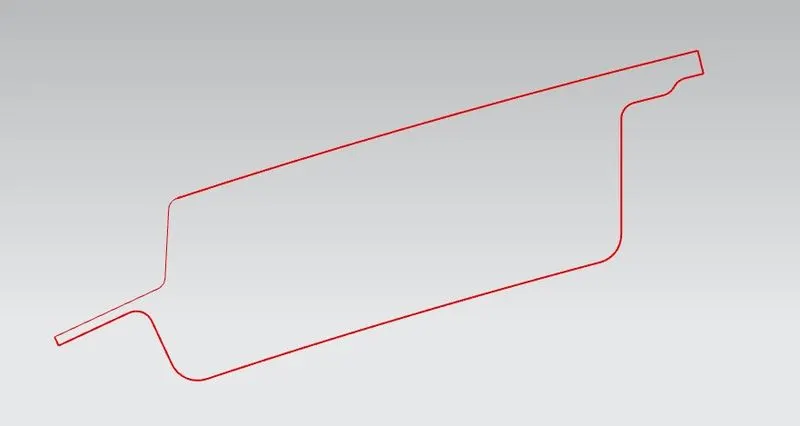
Fig shows: O-Y cross sec view of FRR with outer panel
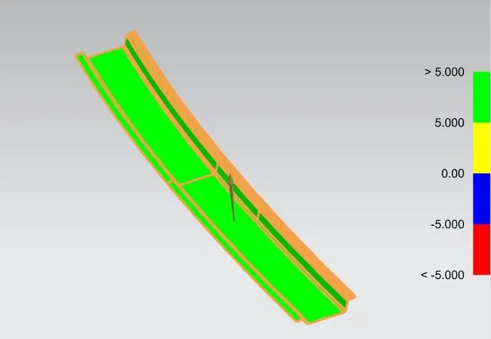
- Draft analysis of FRR is done with minimum tolerance value of 5 degree.
Bow roof rail:
- It is the reinforcement provided under the roof at several sections where the roof surface is mostly flat and needs to be reinforced efficiently.
- All the bow roof rails are placed between the FRR and RRR.
- To increase the roof strength where the bow roof is positioned based on the heat distortion and snow load criteria by doing curvature study.
- Necessary mastic points are provided to join the bow roof with the roof outer panel.
- Embosses are provided all over the bow roof to increase the stiffness.
- Bow roof can be incorporated along with Centre Reinforcement Rail. In this design Bow roof-2 is combined with the centre reinforcement.
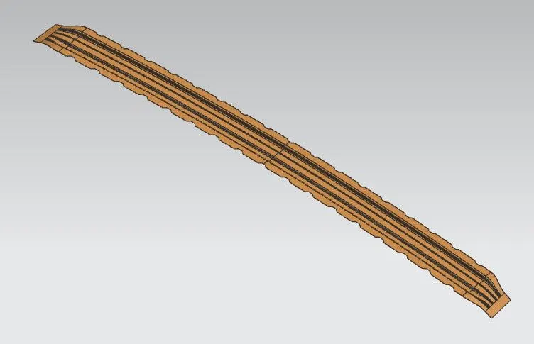
Fig shows: Bow Roof-1
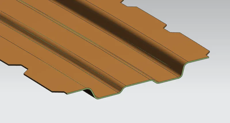
Fig shows: Bow Roof-1 cross section view
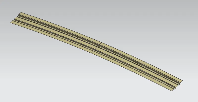
Fig shows: Bow Roof-2

Fig shows: Bow Roof-3
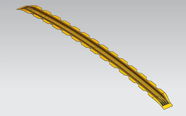
Fig shows: Bow Roof-4
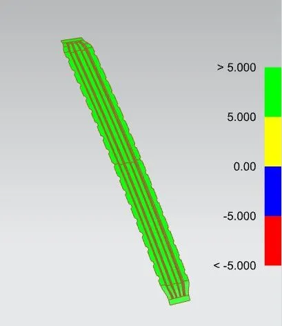
- Draft analysis of BR1 is done with minimum tolerance value of 5 degree.
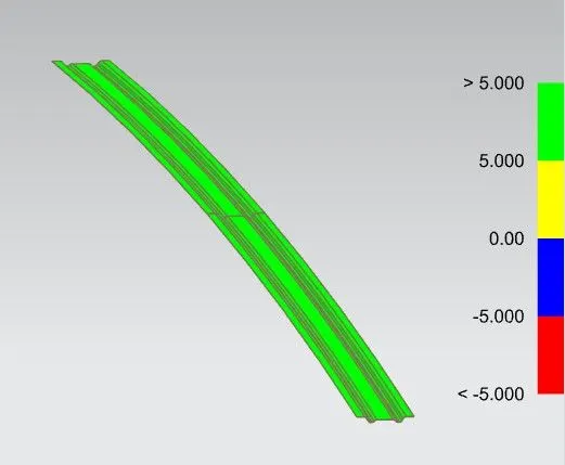
- Draft analysis of BR2 is done with minimum tolerance value of 5 degree.
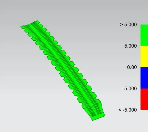
- Draft analysis of BR3 is done with minimum tolerance value of 5 degree.
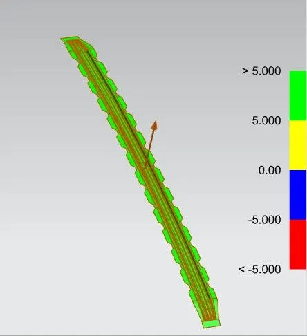
- Draft analysis of BR4 is done with minimum tolerance value of 5 degree.
Centre Reinforcement Roof Rail-
- It is another reinforcement provided at the centre most portion of the roof.
- It can be accompanied with bow roof rail and fixed with the roof panel.
- The centre reinforcement alone doesnot come in contact with the roof panel whereas if it includes bow roof then the bow roof can be joined with roof top by means of mastic points.
- The CRR is used for the centre room lamp bracket mountings and other needs.
- Head room clearance has to be considered for the CRR design aspects.
- In small cars with curved roof top, there is no need of much bow roofs to be installed. Instead the CRR alone with integrated bow roof design can be used and it generally meets the required functions of the roof.
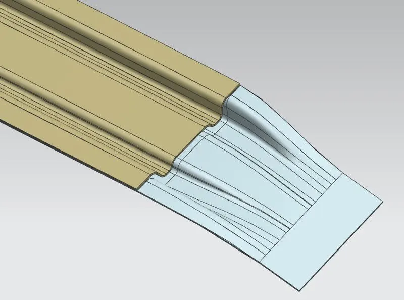
Fig shows: Centre Roof Reinforcment with Bow roof-2
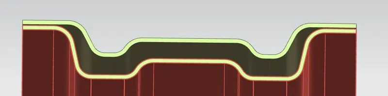
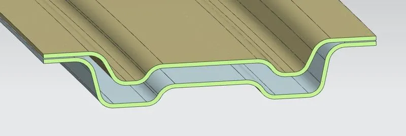
Fig shows: O-Y Cross section view of CRR
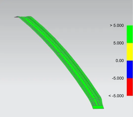
- Draft analysis of CRR is done with minimum tolerance value of 5 degree.
Rear Roof Rail:
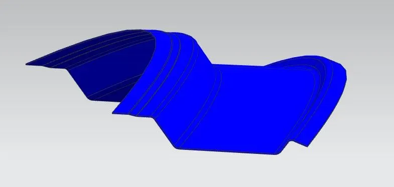
- Rear Roof Rail joins the roof panel with the back door hinge and the body side panel.
- It provides the strength to the roof to hold the back door assembly and provides necessary space for is function.
- Rear visibility criteria and head room clearance are to be considered while designing the RRR.
- There must be necessary clearance provided in the Roof-Backdoor junction for allowing the backdoor panel edge to swing when opening and closing of the backdoor.
- It has a unique cross section for allowing the backdoor functions.
- It is the final reinforcement provided at the extreme end of the roof panel.
- The RRR is designed based on the master section provided.
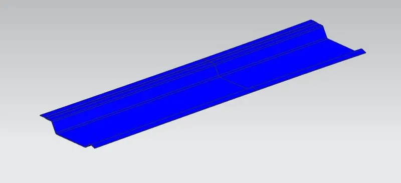
Fig shows: Rear Roof Rail design of the Roof panel
- Master section provided-
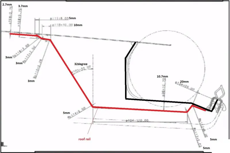
Fig shows: Master section of Rear Roof Rail
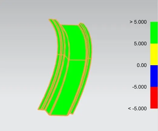
- Draft analysis of RRR is done with minimum tolerance value of 5 degree.
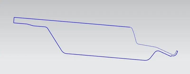
Fig shows: O-Y cross sec view of RRR with outer panel
Section modulus analysis:
- The modulus of inertia at the O-Y section of all the roof rails are obtained using the Section Inertia Analysis command and it is further used for calculating the section modulus.
- This section inertia is also needed for the snow load condition calculation.
Section Inertia analysis of FRR at O-Y section-
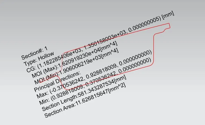
`Iy=1.906006219e^(+03)mm^4`
`y=57.4mm`
`S=(Iy)/y`
`S=1.906006219/57.4xx10^3`
`S=33.20568326mm^3`
Section Inertia analysis of BR1 at O-Y section-
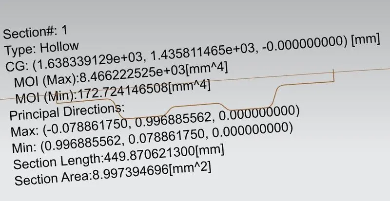
`Iy=172.724146508mm^4`
`y=51.64mm`
`S=(Iy)/y`
`S=172.724146508/51.64`
`S=3.3447743mm^3`
Section Inertia analysis of CRR at O-Y section-
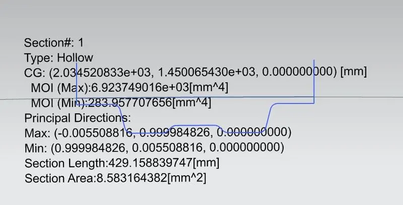
`Iy=283.957707656mm^4`
`y=47.97mm`
`S=(Iy)/y`
`S=283.957707656/47.97`
`S=5.913485254mm^3`
Section Inertia analysis of BR3 at O-Y section
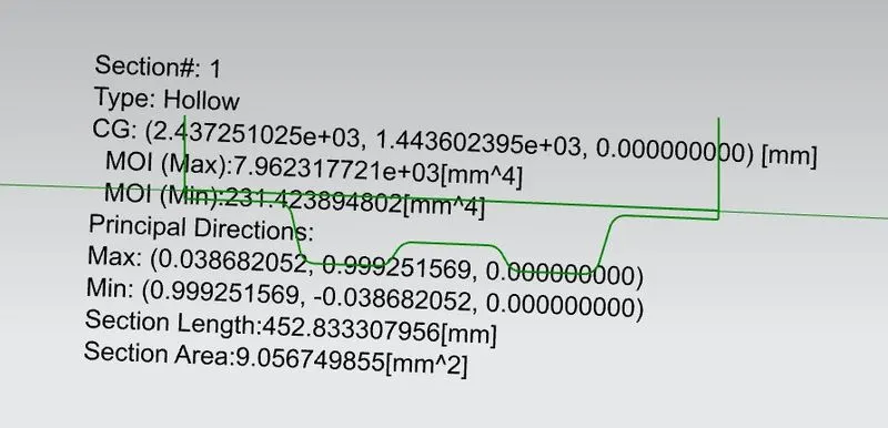
`Iy=231.423894802mm^4`
`y=50.98mm`
`S=(Iy)/y`
`S=231.423894802/50.98`
`S=4.533948877mm^3`
Section Inertia analysis of BR4 at O-Y section

`Iy=190.637894134mm^4`
`y=37.23mm`
`S=(Iy)/y`
`S=190.637894134/37.23`
`S=5.121232885mm^3`
Roof Curvature study:
- Roof curvature study is a numerical method for justifying the position of the bow roofs across the roof panel.
- It can be done as heat distortion criteria and Snow load criteria.
- By using these calculations and comparing the result with the judgemental conditions, the position of the bow roof can be modified accordingly.
a.Heat distortion criteria
Formula,
W = [1.73 x 10^(-3) x L] + [1.85 x 10^(-8) x (R^2)/t] + [ 1.10x10^(-3) x l] - 2.68
Judgement Condition : OK< 2.7> 3.1
Where
L = Roof Length in X-Direction[mm](Roof dimension in 0-Y)
R = Roof curvature
R = 2(Rx*Ry)/(Rx+Ry)
Rx = X curvature
Ry = Y curvature
t = Roof plate thickness [mm]
l = Bow Roof Span [mm]
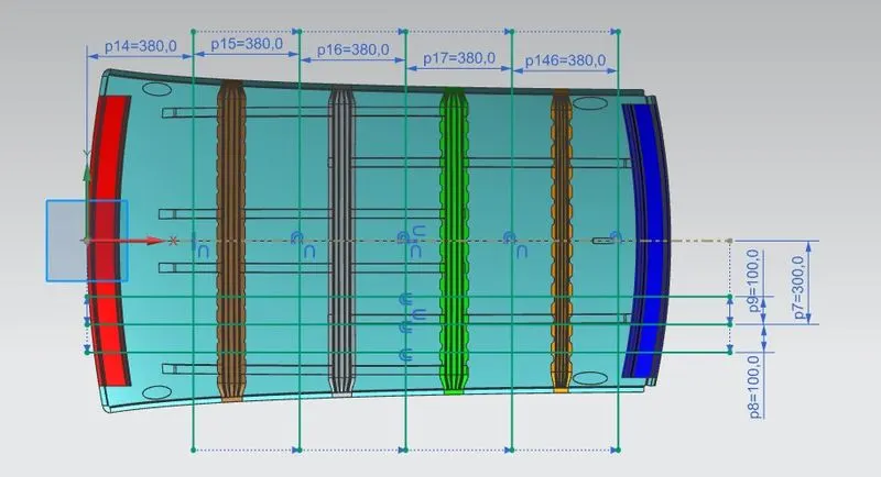
Fig shows: Applying Heat distortion conditions at -3Y section
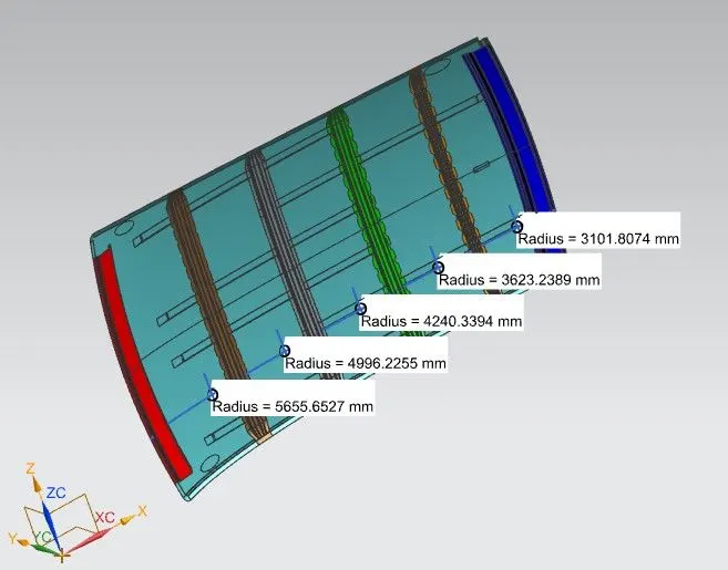
Fig shows: Rx values in Heat distortion method
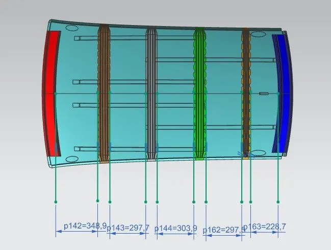
Fig shows: Bow Roof span
Sample calculation for Heat distortion criteria,
FRR - BR1 section
W = [1.73 x 10^(-3) x L] + [1.85 x 10^(-8) x (R^2)/t] + [ 1.10x10^(-3) x l] - 2.68
To find,
R=?
L=?
l=?
W=?
Solution-
`R=2[(Rx xx Ry)/(Rx+Ry)]`
Obtained values,
`Rx=5655.65mm` ; `Ry=2945.3mm` ; `L=2033.7mm` ; `t=0.75mm`; `l=348.9mm`
`R=2[(5655.65xx2945.3)/(5655.65+2945.3)]`
`R=3873.43mm`
`W=[1.73xx10^-3xx2033.7]+[1.85xx10^-8xx3873.43^2/0.75]+[1.10xx10^-3xx348.9]-2.68`
`W=1.59`
Since, `W=1.59<3.1` , it satisfies the condition and hence approved as OK
Similarly,
| HEAT DISTORTION CRITERIA | ||||||||
| SECTION | Rx | Ry | R | l | t | L | W | RESULT |
| FRR- BR1 | 5655.65 | 2945.3 | 3873.43 | 348.9 | 0.75 | 2033.7 | 1.59 | OK |
| BR1-CRR | 4996.23 | 6689.25 | 5720.1 | 297.5 | 1.97 | OK | ||
| CRR-BR3 | 4240.34 | 10147.2 | 5981.22 | 303.9 | 2.05 | OK | ||
| BR3-BR4 | 3623.23 | 14325.6 | 5783.65 | 297.5 | 1.99 | OK | ||
| BR4-RRR | 3101.81 | 15421.1 | 5164.74 | 228.69 | 1.75 | OK | ||
- The above table shows the result of the heat distortion criteria analysis of the roof and ensures the position of the bow roof rails.
- Since all the W values are below 3.1, the bow roofs pass the heat distortion criteria condition.
b. Snow load criteria
Snow load Prediction formula
Qr = [Iy x t2] / [α x s x [(Rx + Ry)/2]2 x 10-8]
Where
α = My x Lx2 x 10-12 , My = Y(Ly-Y)
Judgement condition = Qr ≥ 3.1
250 ≤ s ≤ 380
t = Roof plate thickness [mm]
Ly = Distance between the front and rear roof Rails on the Vehicle along with 0Y[mm]
Length of Roof panel with the center point between Roof rail Front /Rear as the front and rear reference point.
Lx = Distance between the Left and Right end of the roof on the Roof BOW [mm]
Width of the roof panel exposed on the surface.
Y = Distance front Front Roof Rail to Roof BOW[mm]
s = Distance for which Roof BOW bears divided load [mm]
s = L1/2 + L2/2
Iy = Geometrical moment of inertia of Roof BOW (Y cross-section )[mm4]
Rx = Lateral direction curvature radius of roof panel Y cross-section on Roof BOW [mm]
Roof panel curvature Radius of the Length Lx in Front view
Ry = Longitudinal Direction curvature radius of the Roof panel X cross-section on Roof BOW [mm]
Roof panel X curvature radius of length s in Side view
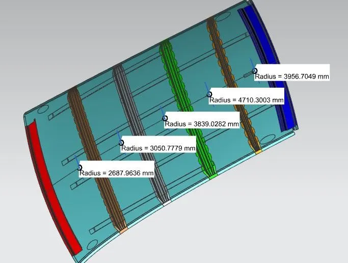
Fig shows: Rx values of snow load criteria at O-Y section
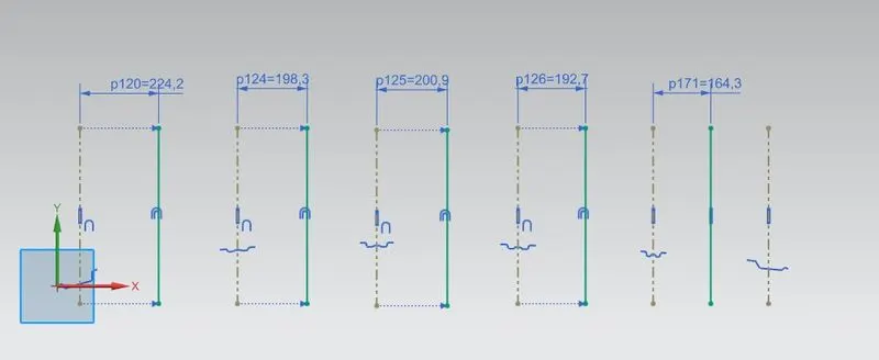
Fig shows: Obtaining Ly value for snow load condition
Sample calculation for snow load criteria,
FRR-BR1 section
Qr = [Iy x t2] / [α x s x [(Rx + Ry)/2]2 x 10-8]
To find,
`Qr=?`
`Iy=?`
`alpha=?`
`s=?`
`Rx=?` ; `Ry=?`
Solution,
`alpha=MyxxLx^2xx10^-12`
`My=Y(Ly-Y)`
`s=(L1)/2+(L2)/2`
Obtained values from the design-
`Iy=172.7mm^4` ; `t=0.75mm` ; `Rx=2687.96mm` ; `Ry=2482.3mm`
`Lx=1127.25mm` ; `Ly=2033.7mm` ; `L1=448.3mm` ; `L2=388.2mm` ; `Y=448.3mm`
`My=Y(Ly-Y)`
`My=448.3(2033.7-448.3)`
`My=710734.82mm^2`
`alpha=MyxxLx^2xx10^-12`
`alpha=710734.82xx1127.25^2xx10^-12`
`alpha=0.9`
`s=(L1)/2+(L2)/2`
`s=(448.3)/2+(388.2)/2`
`s=418.2mm`
`Qr=[Iyxxt^2]/[alphaxxsxx[(Rx+Ry)/2]^2xx10^-8]`
`Qr=[172.7xx0.75^2]/[0.9xx418.2xx[(2687.96+2482.3)/2]^2xx10^-8]`
`Qr=3.86`
Since `Qr=3.86>3.1` , it satisfies the judgement condition the bow roof passes the Snow load criteria.
Similarly,
| SNOW LOAD CRITERIA | |||||||||||
| Section | Iy | `alpha` | Lx | Ly | s | Y | t | Rx | Ry | Qr | RESULT |
| FRR-BR1 | 172.7 | 0.9 | 1127.25 | 2033.7 | 418.2 | 448.3 | 0.75 | 2687.96 | 2482.3 | 3.86 | OK |
| BR1-CRR | 283.9 | 0.75 | 1088.42 | 387.3 | 388.2 | 3050.78 | 5566.5 | 3.2 | OK | ||
| CRR-BR3 | 231.42 | 0.72 | 1065.2 | 385.8 | 386.4 | 3839.02 | 9203.8 | 1.16 | NOT OK | ||
| BR3-BR4 | 190.6 | 0.7 | 1050.46 | 356.9 | 385.3 | 4710.3 | 13532.1 | 0.52 | NOT OK | ||
| BR4-RRR | 798.2 | 0.61 | 1041.26 | - | 328.5 | 3956.7 | 17595.8 | - | - | ||
- From the above table it is clear that the first bow roof and the centre reinforcement rail passes the snow load criteria and the rest of the bow roofs fails inspite of the various changes that has been made to the position and cross-section of the respective bow roofs as much as possible.
- This indicates that the roof may fail to snow load bearing condition due to deficiendy in strength of the roof.
- Hence, embosses have been provided on the top surface of the roof for increasing the roof strength.
Design optimization:
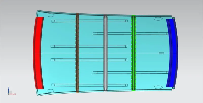
Fig shows: Initial stage design of the roof
- At first only 3 bow roofs were provided for the design.
- After doing curvature study all the positions of the bow roofs were found to be failed during calculations. Hence, several changes have been made like increasing the depth of the bow roof and varying its position accordingly and another bow roof is added to the design to minimise the "s" value.
- Further doing optimum changes the final design is achieved.
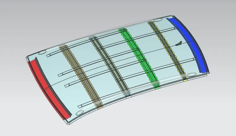
Fig shows: FInal design with all the reinforcements
Images of the final outcome of the design:
Conclusion:
- Hence the design is done with all the reinforcements and necessary analysis and curvature study is performed.
- From the curvature study it is found that the failure in the snow load criteria is due to the increased value of Ry (i.e. the curvature at O-Y rear sections). To overcome this, the minimum MOI of the bow roof has to be raised drastically(More than `1500mm^4` ), so that the bearing capacity of the bow roof also can be increased.
- Or the no of bow roofs can be increased if possible with the budget of the project.
- In other way the curvature of the rear roof can be increased without being left as flat as possible. This shows that when the roof has a better curved surface the Ry value at specific section decreases, in other hand the flat surface has more Ry value than the curved surface.
- Yet the design passes the heat distortion criteria and provides a reliable condition.
- To compensate the strength lost embosses are provided along the roof panel which will increase the strength and stiffness of the roof more than enough.