Roof challenge
An automobile roof or car top is the portion of an automobile that sits above the passenger compartment, protecting the vehicle occupants from sun, wind, rain, and other external elements.
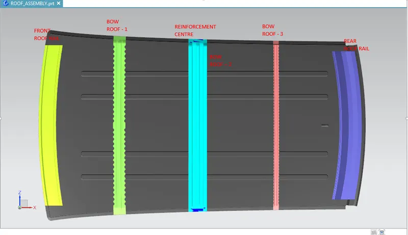
The objective of this assignment is to design the roof of the car and the Front and Rear roof rail and different Reinforcements that are given in order to strengthen the roof and to resist different loads.
DESIGN PARAMETERS:
1. The roof must be designed in such a way that there is enough room for Head Clearance region for different persons and this parameter can vary from region to region.
2. While designing the Roof we must keep in mind about the Head impact Zone during crash or collision so that the head of the driver and passengers does not collide with the roof of the car during collision or crash.
3. While designing the Front Roof Rail we must keep in mind about the Visibility Region of the driver so the driver does not face any issue while driving.
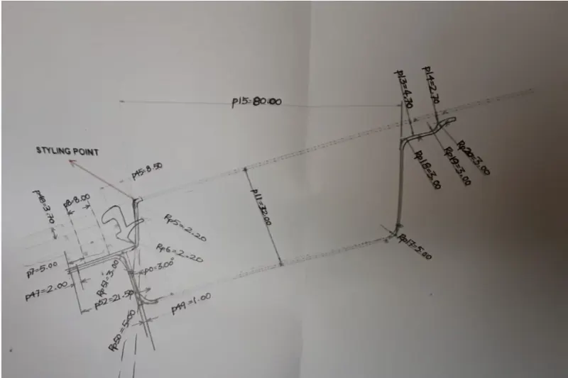
4. To satisfy Visibility Criteria the Flange drawn should be at angle exactly `3^o`. If the angle is increased then in order to satisfy the flange length it increases towards outward direction which decreases the visibility criteria.
5. Bow Roofs are provided in order to increase the strength of the vehicle and resist various loads.
6. The positioning of the Bow Roofs and Reinforcement Centre are done by the 'Heat Distortion Criteria' and 'Snow Load Criteria'.
7. The Bow Roofs are provided on the flat surfaces to increase the strength of the roof and load resisting capacity.
8. The number of Bow roofs depend on the size of the car and flatness of the surface.
9. While designing the Inner flange of different parts there must be a gap of 5mm for the Mastic Sealants to join the Part with the Inner side of the Roof Outer.
DESIGN OF THE ROOF:
1. FRONT ROOF RAIL:
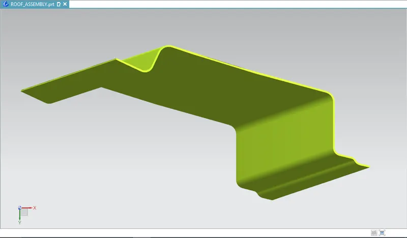
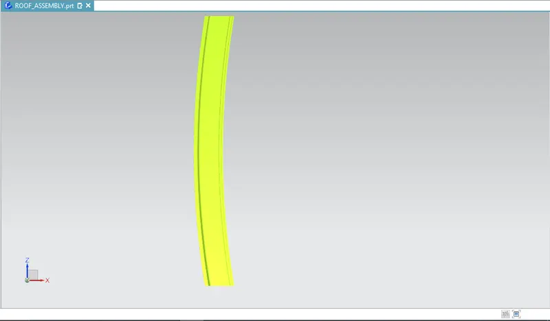
Front Roof Rail is the part that joins the Windshield of the car to the Body side outer.
MASTER SECTION
PART:
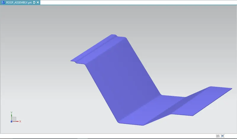
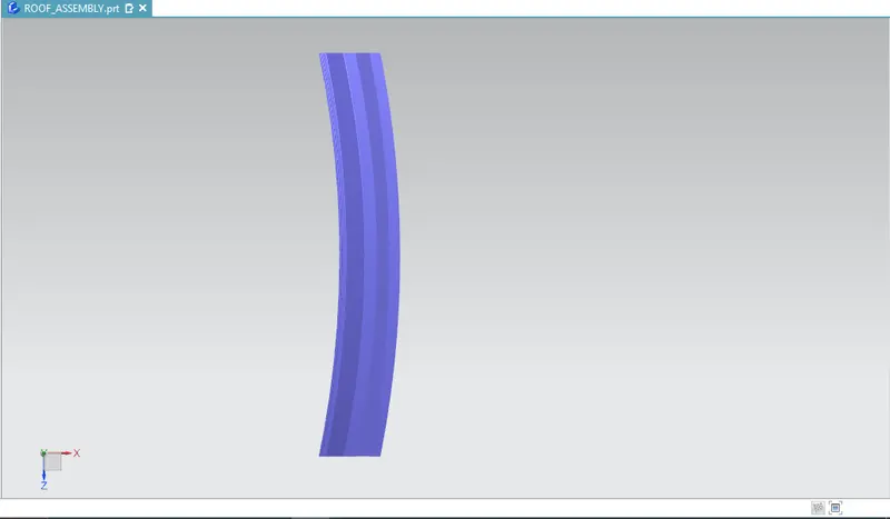
2. REAR ROOF RAIL :
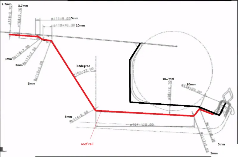
The Rear Roof Rail is the part that which joins the Back Door and the Body side outer.
MASTER SECTION
PART :
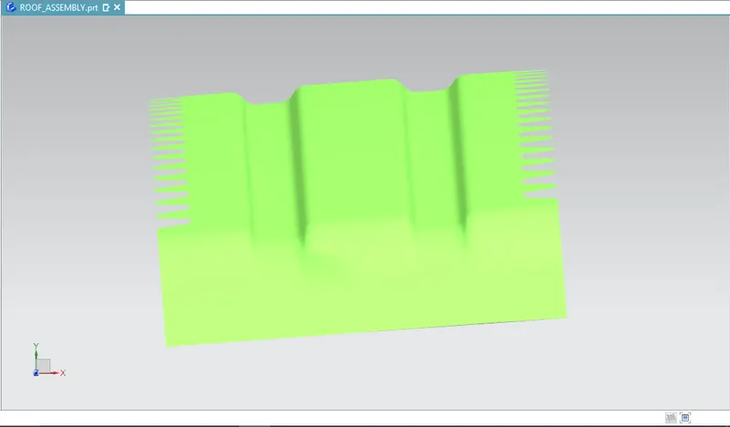
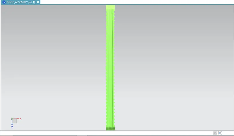
3. BOW ROOF-1 :
Bow Roofs are provided to increase the strength of the car roof and to resist maximum load on the roof outer.
Bow roofs are placed where the surface is flat.
PART :
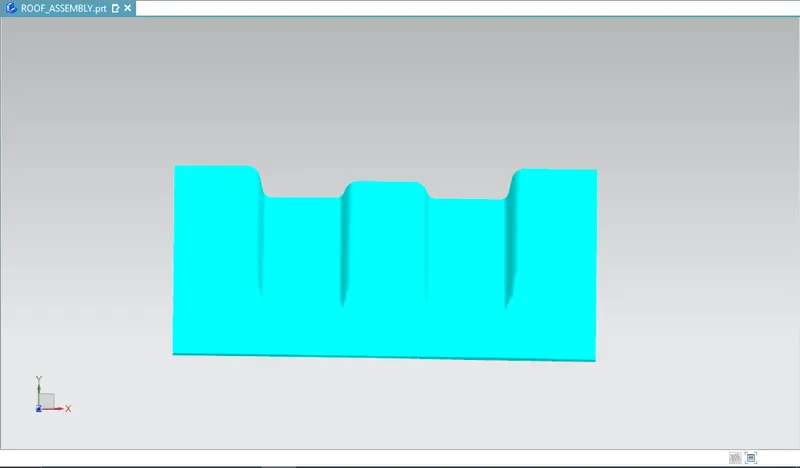
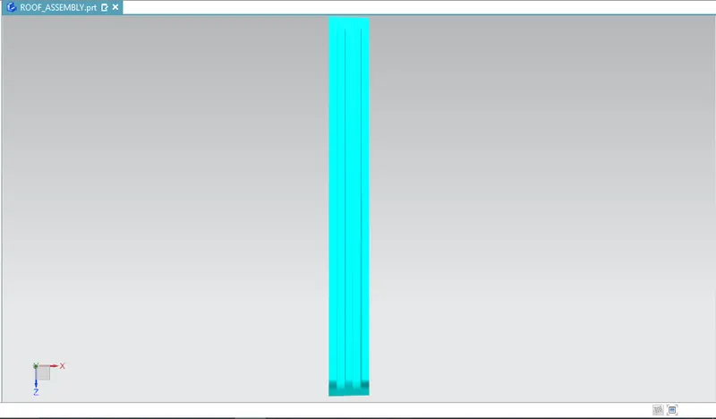
6. REINFORCEMENT CENTRE :
Reinforcement Centre is provided at the Centre of the Roof in order to provide support to the roof and also to increase the strength of the roof and resist maximum load falling on the roof outer,
PART :
5. BOW ROOF-2 :
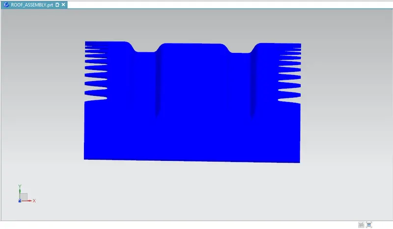
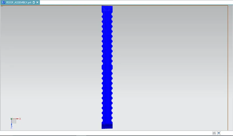
Bow Roofs are provided to increase the strength of the car roof and to resist maximum load on the roof outer.
Bow roofs are placed where the surface is flat.
This Part is provided inside the Reinforcement Centre.
PART :
6. BOW ROOF-3 :
Bow Roofs are provided to increase the strength of the car roof and to resist maximum load on the roof outer.
Bow roofs are placed where the surface is flat.
PART :
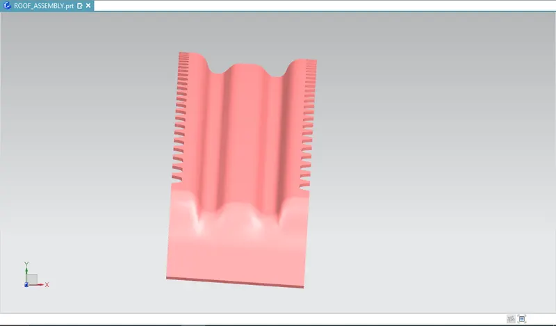
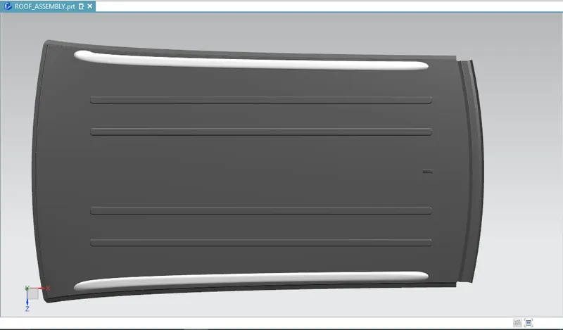
7. ROOF OUTER :
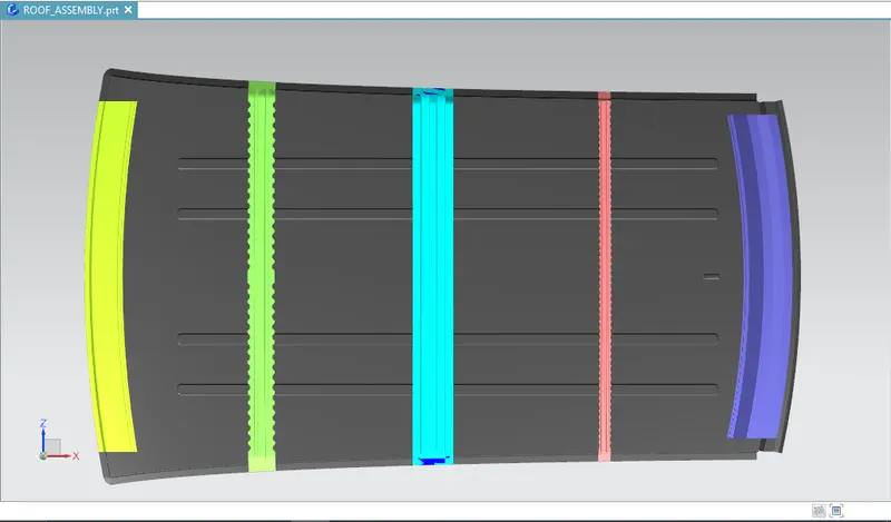
DRAFT ANALYSIS:
1. ROOF OUTER
2. FRONT ROOF RAIL
3. REAR ROOF RAIL
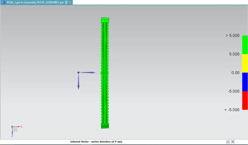
4. BOW ROOF 1
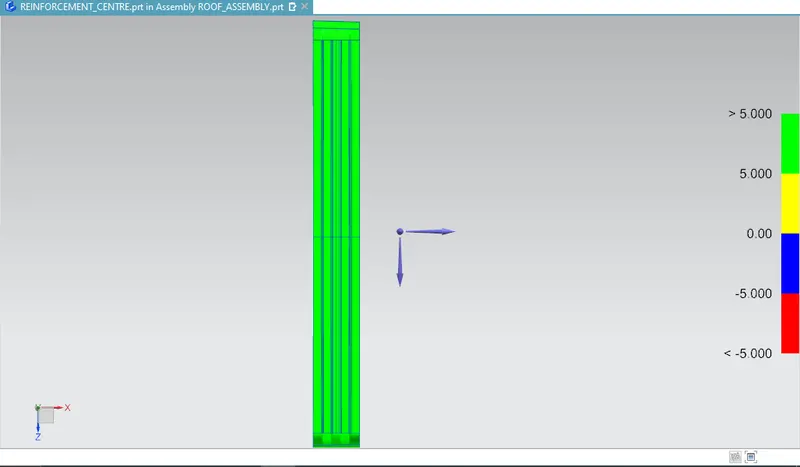
5. REINFORCEMENT CENTRE
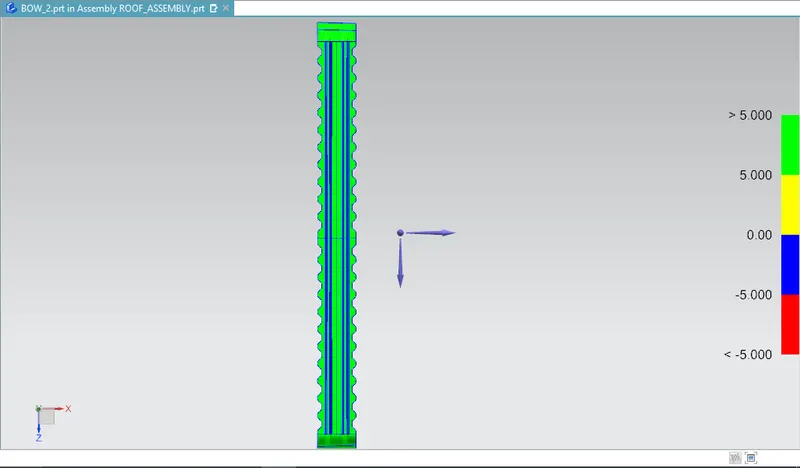
6. BOW ROOF 2
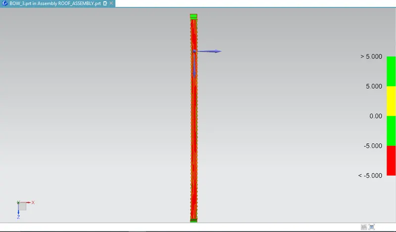
7. BOW ROOF 3
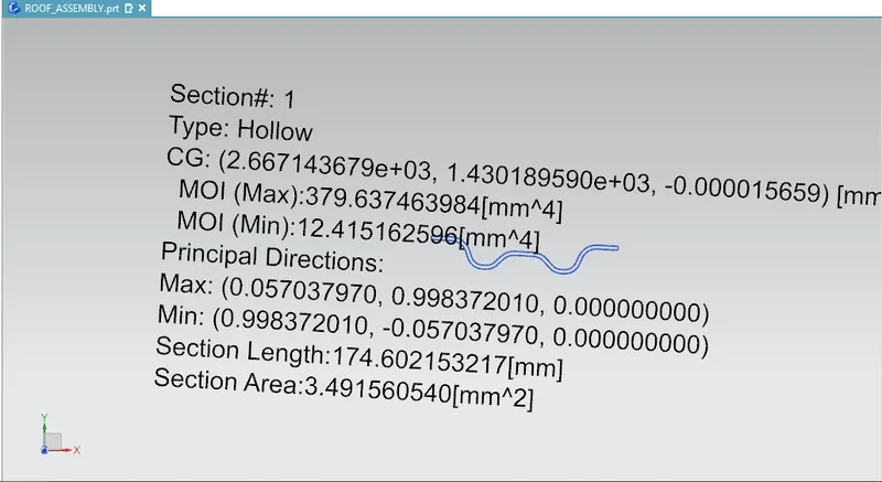
SECTION INERTIA ANALYSIS:
1. FRONT ROOF RAIL
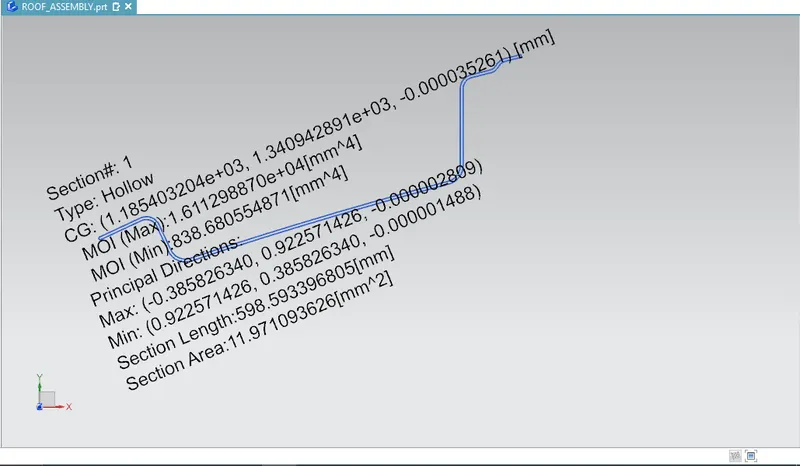
2. REAR ROOF RAIL :
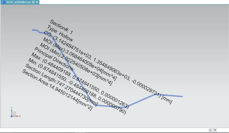
3. BOW ROOF 1
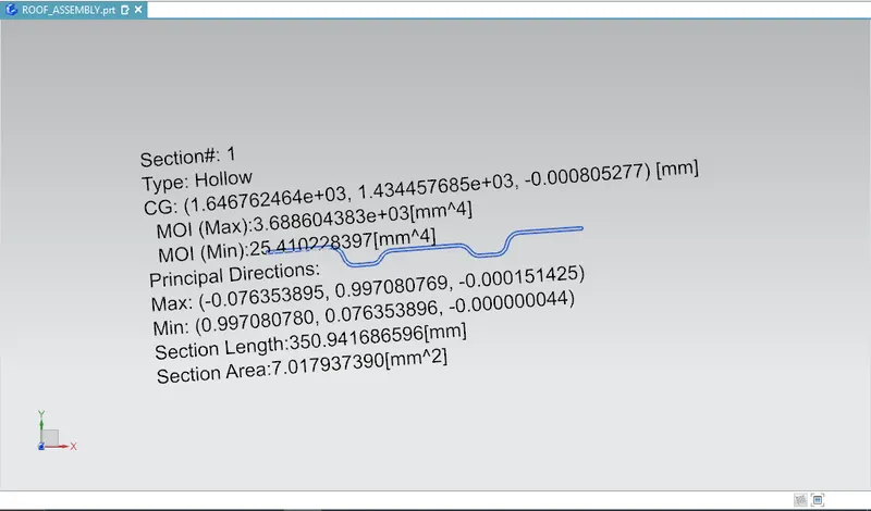
4. REINFORCEMENT CENTRE :
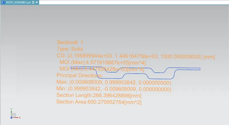
5. BOW ROOF 3
CURVATURE STUDY:
The curvature study on the roof is done in order to determine the position of the Bow roofs so that it resists the load in the outer surface of the roof and provides maximum strength to the roof.
1. HEAT DISTORTION CRITERIA :
Bow–roof prediction Formula
W = [1.73 x 10^(-3) x L] + [1.85 x 10^(-8) x (R^2)/t] + [ 1.10x10^(-3) x l] - 2.68
Judgement Condition : OK< 2.7> 3.1
Where
L = Roof Length in X-Direction[mm](Roof dimension in 0-Y)
R = Roof curvature
R = 2(Rx*Ry)/(Rx+Ry)
Rx = X curvature
Ry = Y curvature
t = Roof plate thickness [mm]
l = Bow Roof Span [mm]
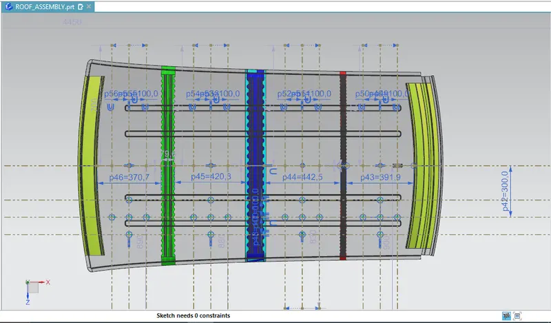
CALCULATIONS:
| SL NO. | SECTION | RX (mm) | RY (mm) | R (mm) | l (mm) | L (mm) | W | RESULT |
| 1. | FRONT ROOF RAIL & BOW ROOF 1 | 3985.5066 | 2472.4777 | 3051.7501 | 370.84 | 2031.767 | 1.47 | OK |
| 2. | BOW ROOF 1 & REINFORCEMENT CENTRE | 4555.7965 | 6157.3568 | 5236.8642 | 420.2432 | 2031.767 | 1.97 | OK |
| 3. | REINFORCEMENT CENTRE & BOW ROOF 3 | 4969.5641 | 10376.1125 | 6720.4278 | 442.4821 | 2031.767 | 2.43 | OK |
| 4. | BOW ROOF 3 & REAR ROOF RAIL | 5049.6303 | 14619.2981 | 7506.46 | 391.934 | 2031.767 | 2.54 | OK |
2. SNOW LOAD CRITERIA :
Qr = [Iy x t2] / [α x s x [(Rx + Ry)/2]2 x 10-8]
Where
α = My x Lx2 x 10-12 , My = Y(Ly-Y)
Judgement condition = Qr ≥ 3.1
250 ≤ s ≤ 380
t = Roof plate thickness [mm]
Ly = Distance between the front and rear roof Rails on the Vehicle along with 0Y[mm]
Length of Roof panel with the center point between Roof rail Front /Rear as the front and rear reference point.
Lx = Distance between the Left and Right end of the roof on the Roof BOW [mm]
Width of the roof panel exposed on the surface.
Y = Distance front Front Roof Rail to Roof BOW[mm]
s = Distance for which Roof BOW bears divided load [mm]
s = L1/L2 + L2/2
Iy = Geometrical moment of inertia of Roof BOW (Y cross-section )[mm4]
Rx = Lateral direction curvature radius of roof panel Y cross-section on Roof BOW [mm]
Roof panel curvature Radius of the Length Lx in Front view
Ry = Longitudinal Direction curvature radius of the Roof panel X cross-section on Roof BOW [mm]
Roof panel X curvature radius of length s in Side view
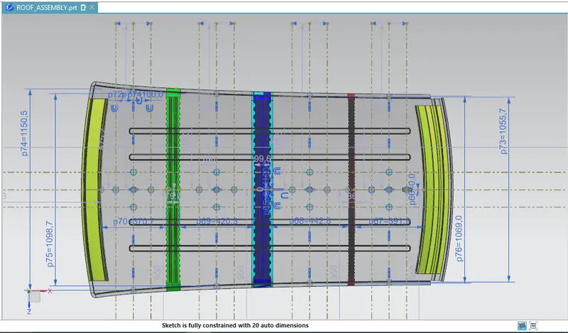
CALCULATIONS:
| SL NO | SECTION | RX (mm) | RY (mm) | l (mm) | Lx (mm) | Ly (mm) | Y (mm) | L1 (mm) | L2 (mm) | My | a | S | MOI (mm^4) | Qr | RESULT |
| 1. | FRONT ROOF RAIL & BOW ROOF 1 | 4576.5657 | 2535.9909 | 370.84 | 1151.0 | 2031.767 | 475.4783 | 475.4783 | 510.3354 | 740092.2918 | 0.9804 | 256.099 | 3688.604 | 65.34 | OK |
| 2. | BOW ROOF 1 & REINFORCEMENT CENTRE | 3762.8244 | 6063.4281 | 420.2432 | 1098.7 | 2031.767 | 510.3354 | 510.3354 | 512.4415 | 776559.3123 | 0.9374 | 257.2166 | 4.571e05 | 4418.28 | OK |
| 3. | REINFORCEMENT CENTRE & BOW ROOF 3 | 4284.6063 | 11207.9065 | 442.4821 | 1069.0 | 2031.767 | 512.4415 | 512.4415 | 506.0 | 778684.8370 | 0.8898 | 254.0127 | 379.637 | 0.393 | NG |
CONCLUSION:
From the above assignment we can conclude that
1. The position of Bow Roof 1 , Reinforcement Centre and Bow Roof 2 are proper as per the Heat Distortion Criteria.
2. But the Section 3 having Reinforcement Centre and Bow roof 3 failed the Snow load criteria due to the Moment of Inertia of Bow Roof 3 so as a corrective measure we can increase the size of Bow Roof 3 i.e the Cross Sectional Size so that it can withstand the load and pass the Snow Load Criteria.
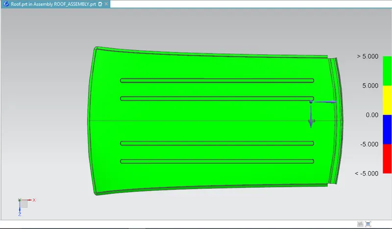
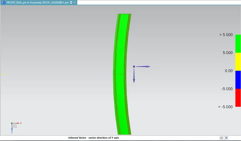
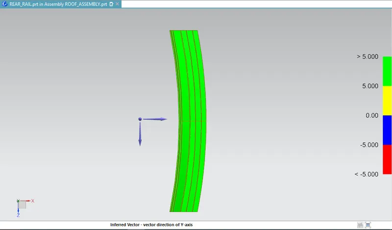
3. From the Draft Analysis we can clearely see that Bow Roof 2 and Bow roof 3 has major Negative drafts so as a corrective measure we need to increase the draft angle of the surfaces where there is a negative draft so that the part can become manufacturable.