Roof challenge
TITLE - TO DESIGN THE ROOF OF A CAR (FRONT ROOF, BOW ROOF, CENTER ROOF, AND REAR ROOF).
OBJECTIVE – To design the front roof rail, bow roof, center roof, and rear roof rail as per the given master sketch and perform the curvature study and check the bow roof prediction and snow load prediction conditions. Also produce draft analysis to produce positive draft for manufacturing.
INTRODUCTION
An automobile roof or car top is the portion of an automobile that sits above the passenger compartment, protecting the vehicle occupants from sun, wind, rain, and other external elements. The roof panel is generally a flat panel like component and according to this particular embodiment is made from light weight aluminum material and includes an outer periphery. Depending on the particular emgbodiment, roof panel may have cut outs for items like sunroofs or windows, it mah have longitudinal ribs, creased or other aerodynamic features or it may be made from a single panel or multiple panels that are joined together.
The size and shape of the attachment flange can vary depending on the particular application but it is generaally designed to allow for a weld or braze seam that attachs roof assembly to the structural members without the need for additional mechanical fasterners like self piercing rivets or adhesive compounds.
Under the styling surface that is seem from the outside, there are many other structures under the roof that contrubute to its strength and stability. The number of such reinforcement structures differ with respect to the size of the vehicle. They are primarily installed on flatter areas of the roof to enhance strength.
ROOF CONSISTS OF THE
- Roof outer panel
- Front roof rail
- Rear roof rail
- Center roof rail
- Bow roofs
DESIGN METHODOLOGY
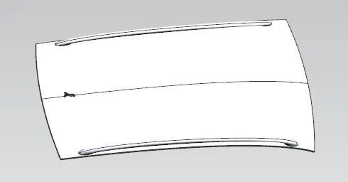
STYLISH SURFACE
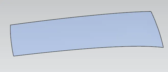
EXTRACTED SURFACE
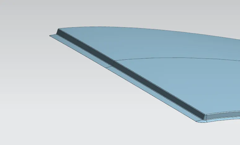
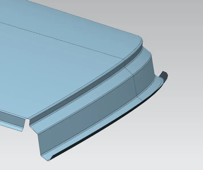
FRONT DITCH AREA
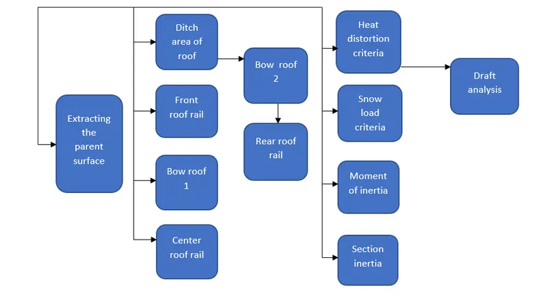
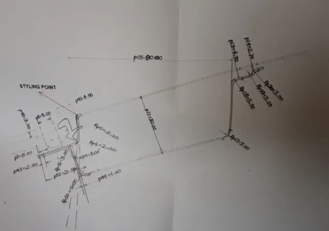
The parent surface is extracted and then ditch area is developed considering the parameter specified in the following master section.Flange of around 15mm is created using law extension command and corner relief is provided at rear flanges and positive draft of more than 3 degrees. Overall thickness of the front ditch is about 0.75 mm.
REAR DITCH AREA
It is same as the front ditch area, it is created by taking the offset of the roof outer panel and providing necessary values to create rear ditch area as per the given master-section. Relief is provided at corners in order to help to eliminate the tool breakage and also increase the tool life.
FRONT ROOF RAIL
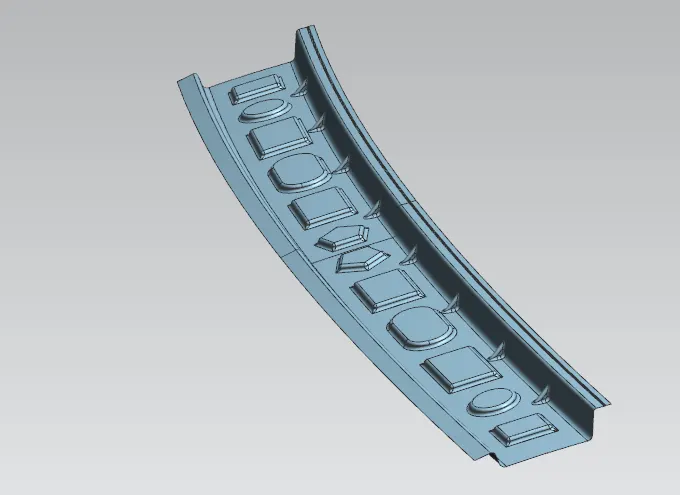
It is an additional part given to the roof as a reinforcement which improves the overall strength of the roof. While designing the front roof rail we need to take some considerations such as
- The opening angle of 3 degrees
- The depth of the front roof rail should match up with visibility criteria.
- The length of the roof should be in accordance with headroom clearance.
MASTER SKETCH
REAR ROOF RAIL
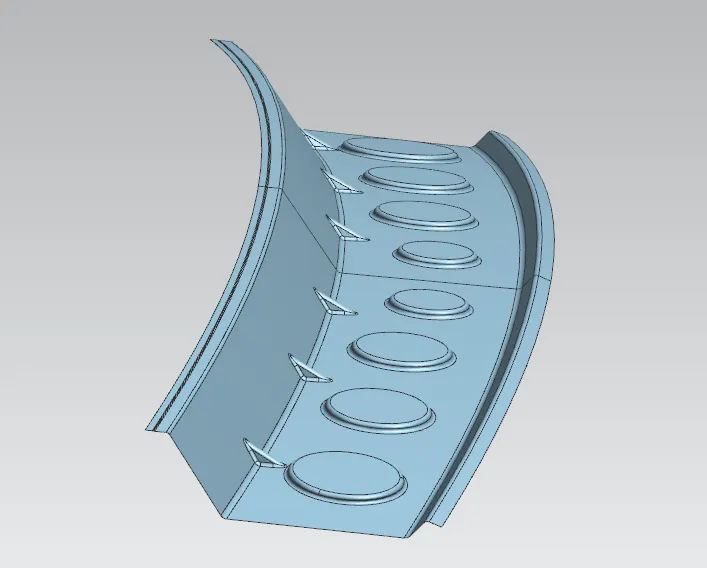
For the rear roof rail, head clearance should be considered as we followed in the front roof rail. The master of the rear roof rail is different compared to other roof rails because of back door attachment.

BOW ROOF
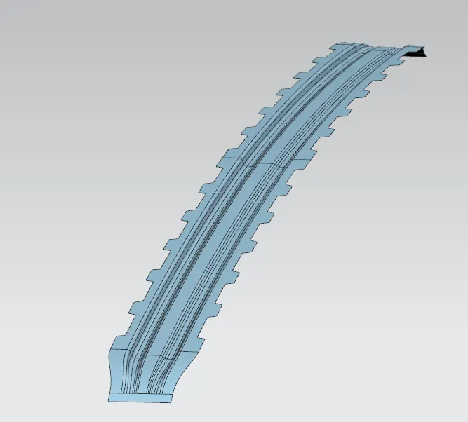
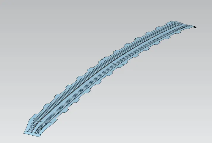
The bow roofs are given to improve the torsional stiffness and load bearing capacity of the roof structure. Longer the roof, more the number of bow roofs are created to the BIW fixture. The positioning of bow roofs done on curvature study, and heat distortion and snow load criteria are checked to analyze the position of the bow roofs.
BOW ROOF 1
BOW ROOF 2
CENTER ROOF RAIL
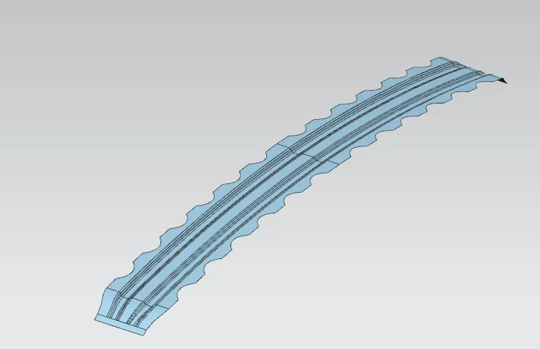
Center roof rail is provided to effectively support the flat area of the rrof as it is more suspectable to failure under the action of external load. It is placed at the center of the roof. Embosses and dart are created for all the roof rails in order to improve the strength of the rail and roof respectively.
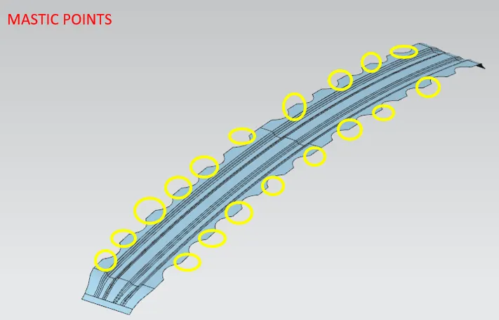
- There should be minimum gap of 5-6 mm between the roof rails, bow roofs and the roof outer panel to place the mastic points. They are used to join the two different parts.
DESIGN CONSIDERATION OF THE ROOF
- Visibility criteria
- Head clearance
- Curvature study
- Front collision
- Heat distortion
- Snow load
- Draft analysis
ROOF CRUSH TEST
The validation for the designed roof is the roof crush test in which the test sample is placed horizontally as shown in the figure below.

The windows and doors of the test sample are closed and locked and the force is applied at a 5degree with respect to the horizontal in the side view and 25 degree with respect to the horizontal in the front view.
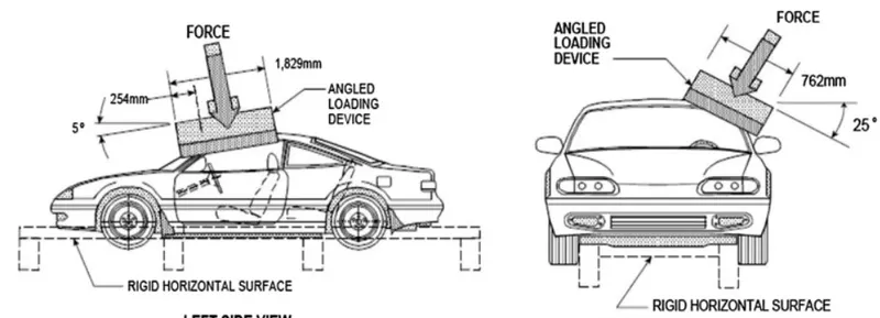
From the above test, the load displacement graph is obtained and if the displacement is more than required then neccessary reinforcement should be added to reduce the displacement.
ROOF TOP VIEW
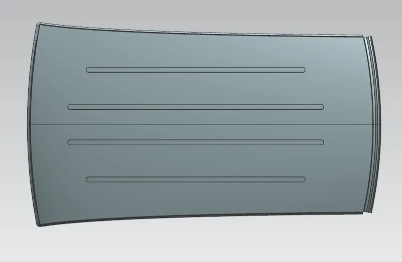
ROOF BOTTOM VIEW
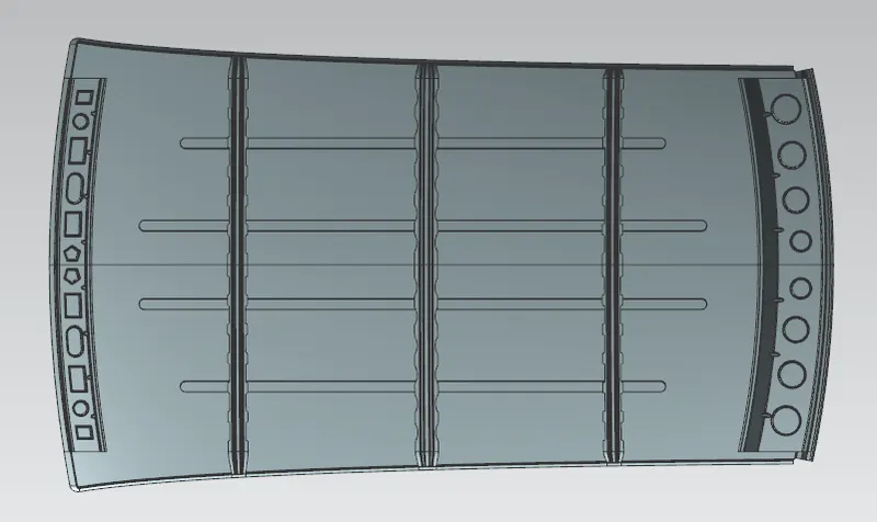
ROOF TRANSPARENT VIEW
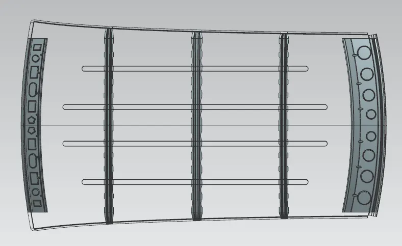
ROOF ISOMETRIC VIEW
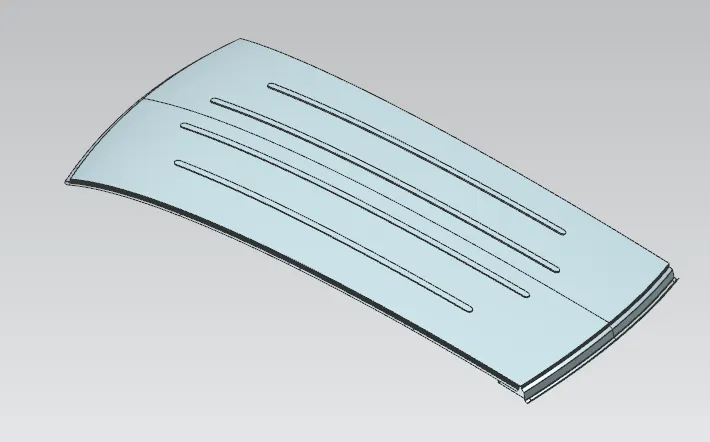
CURVATURE STUDY OF THE ROOF
Heat distortion study plays an important role in sheet metal. It is a temperature limit above which the meaterila cannot be used for structural applicatons. This study is used to predict the heat distortion temperature in order to avoid the bending or damages on roof based on heat distortion temperature and also it determines the postion of bow roofs to strengthen the roof.
Bow roof-prediction formula
W= [1.73 x 10^(-3) x L] +[1.85 x 10^(-8) x (R^2)/t] = [1.10 x 10^(-3) x l] - 2.68
judgement condition : OK<2.7>3.1
Where
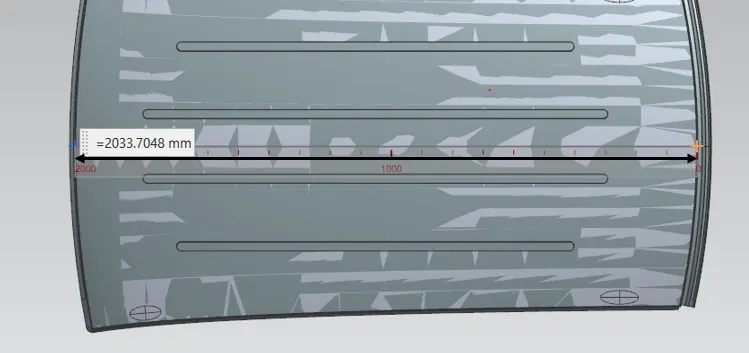
- L= Roof Length in x- direction(mm)(roof dimension in O-Y)
- Here L is the total length of stylish surface as shown in below figure...
- R= Roof curvature
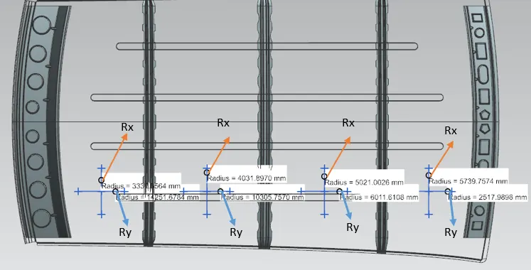
R=2(Rx*Ry)/(Rx+Ry)
Rx= x curvature
Ry= y curvature
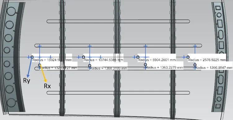
Here at 0-Y axis, at about 3Y 300mm line is drawn parellel to 0-y axis and to that 100mm line is drawn above and below the 3Y line. Draw the centerline between the bow roof and rear roof rail and to that 100mm line is drawn to the left and right side of the centerline, do the same thing for other 3 sections of roof. Then plot the points where the horizontal and vertical lines intersect each other, thus we get the intersection points and join the intersection points with 3point arc. Using these arcs we will find the radius as shown in below figure...
- t= roof plate thickness(mm)
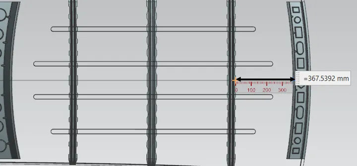
- l= bow roof span (mm)
here l is the distance between bow roof and the rear roof rail as shown in figure..
HEAT DISTORTION TABLE
| ROOF RAILS | Rx | Ry | I | L | T | W | REMARKS |
| FR-BOW1 | 5739.75 | 2517.98 | 367.53 | 2033.7 | 0.75 | 1.54 | OK |
| BOW1-CR | 5021 | 6011.61 | 447.33 | 2033.7 | 0.75 | 2.06 | OK |
| CR-BOW2 | 4031.89 | 10305.75 | 440.66 | 2033.7 | 0.75 | 2.68 | OK |
| BOW2-RR | 3331.65 | 14251.67 | 363.3 | 2033.7 | 0.75 | 1.95 | OK |
From the above table it is found that all the values are with in the given conditions and hence the position of bow roofs are in good state.
SNOW LOAD CRITERIA
This situdy is done to check the durability of the roof to withstand snowfall and reflex back to its original shape without any permanent deformation once the load is removed.
Snow load prediction formula
Qr = [Iy x t^2] / [α x S x [(Rx+Ry)/2]^2 x 10^-8]
where
α = My x Lx^2 x 10^-12 , My = Y(Ly-Y)
judgement condition = Qr ≥ 3.1
250≤S≤380
- t = roof plate thickness (mm)
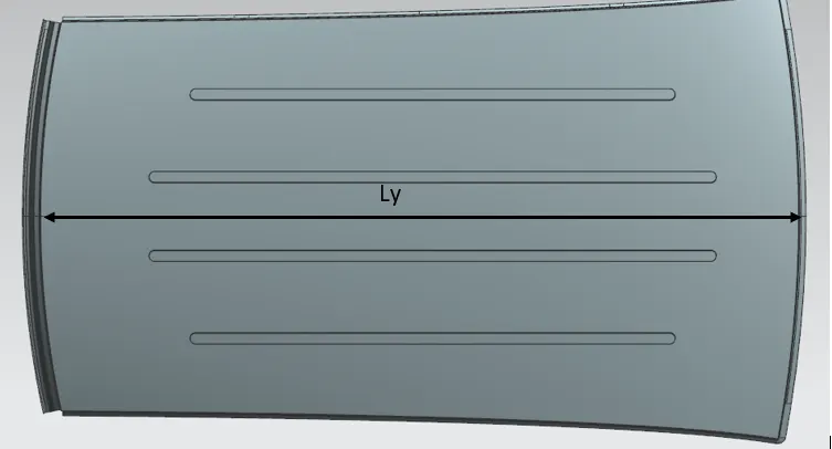
- Ly = distance between the front and rear roof rails on the vehicle along with Oy(mm).
Length of roof panel with the center point between roof rail front / rear as the front and rear reference point.
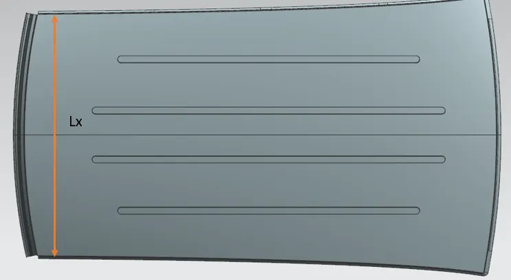
- Lx = distance between the left and right end of the roof on the roof bow (mm).
Width of the roof panel exposed on the surface.
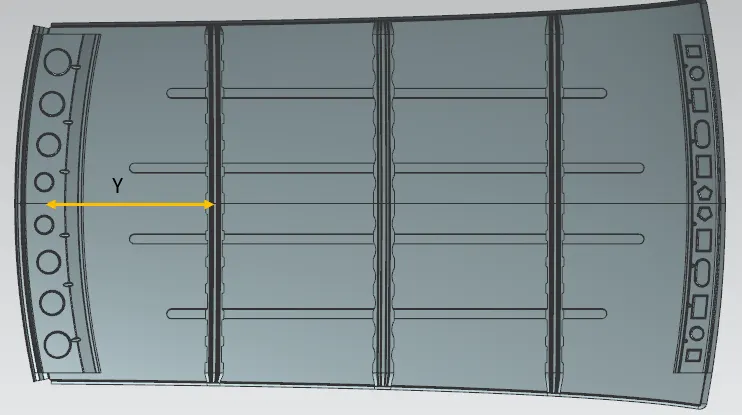
- Y = distance rear roof rail to roof bow(mm).
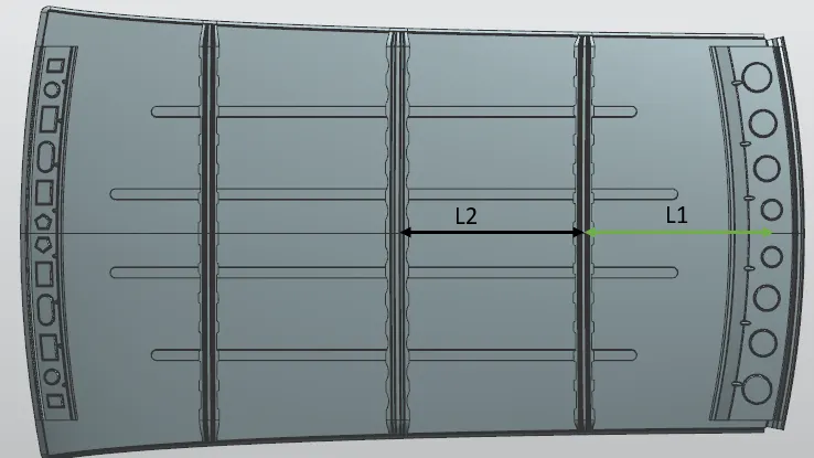
- S = distance for which roof vow bears divided load (mm).
s = L1/2 + L2/2
- Iy = geometrical moment of inertia of roof bow (y cross-section)(mm^4).
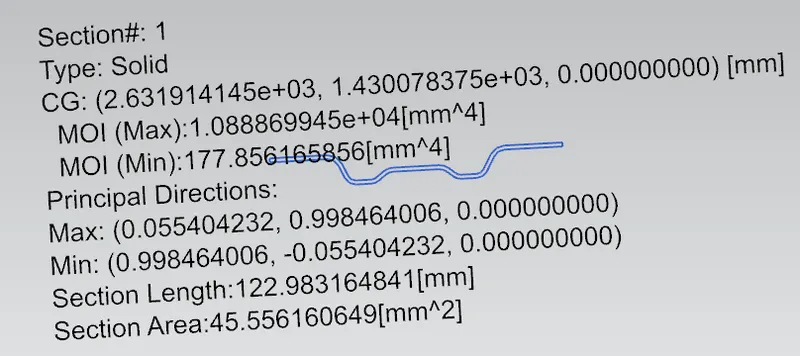
Moment of inertia of bow roof 1
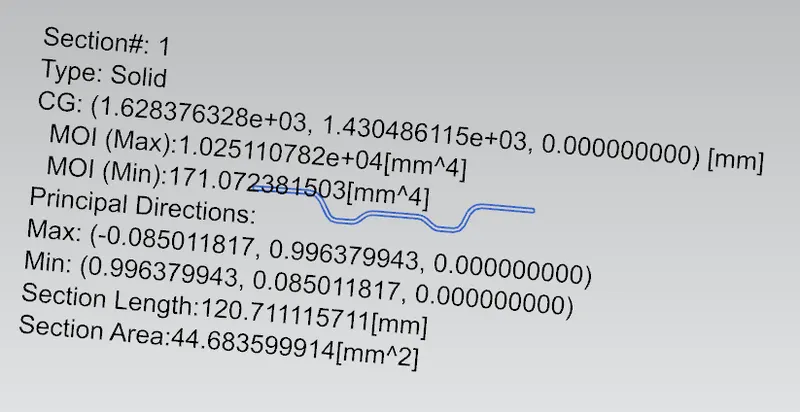
Moment of inertia of bow roof 2
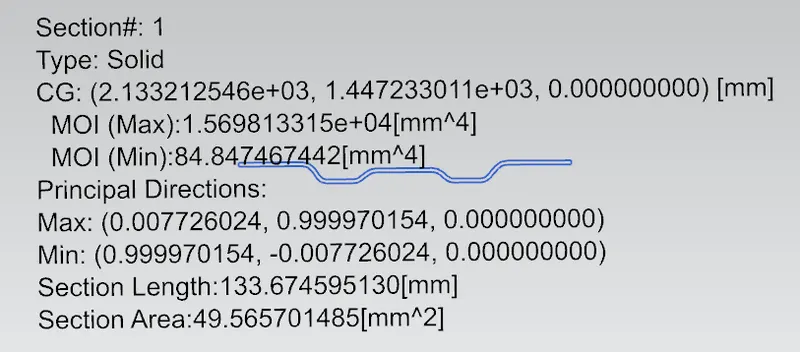
Moment of inertia of center roof rail
- Rx = lateral direction curvature radius of roof panel Ycross-section on roof bow(mm).
roof panel curvature radius of the length Lx in front view.
- Ry = longitudinal direction curvature radius of the roof panel X cross-section on roof bow(mm).
roof panel X curvature radius of length s in side view.
Rx and Ry are formed by creating intersection points, as we created while calculating the heat distortion.
SNOW LOAD CRITERIA TABLE
| ROOF RAILS | L1 | L2 | Lx | Ly | y | Iy | My | α | S | T | Qr | RESULT |
| FR-BOW1 | 444.13 | 505 | 1138.26 | 2033.7 | 444.13 | 171 | 705,975.72 | 0.9125 | 474.56 | 0.75 | 54.79 | OK |
| BOW1-CR | 505 | 498.65 | 1088.68 | 2033.7 | 505 | 84.84 | 771,993.5 | 0.9149 | 501.82 | 0.75 | 1.58 | NG |
| CR-BOW2 | 498.65 | 495.19 | 1059.58 | 2033.7 | 498.65 | 177.85 | 765,452.68 | 0.8593 | 496.92 | 0.75 | 0.61 | NG |
| BOW2-RR | - | - | 1044.9 | 2033.7 | 495.19 | - | - | - | - | 0.75 | - | - |
It is observed that the values of Qr>3.1
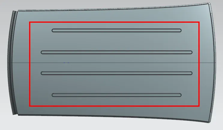
From the above we found that the two values of Qr<3.1, here we can ask the styling team to modify the surface curvature along Y axis. Also we can create the additional embosses on the top of roof to improve the overall strength of the roof as shown in below figure...
- SECTION MODULOUS
The elastic section modulus is defined as S = I / y, where I is the second moment of area (or area moment of inertia, not to be confused with moment of inertia) and y is the distance from the neutral axis to any given fibre.
FOR BOW ROOF1
Moment of inertia(Imax) = 1.088869945 x 10^4 (mm^4)
Moment of inertia(Imin) = 177.856165856 (mm^4)
Section modulus S = MOI / distance between the neutral axis and extreme end of the object.
i.e S = I/Y
For (MOI)max = Imax/Y
= (1.088869945 x 10^4) / 26.7
Smax = 407.81 mm^3
For (MOI)min = Imin/Y
= (177.856165856) / 26.7
Smin = 6.66 mm^3
BOW ROOF2
Moment of inertia(Imax) = 1.025110782 x 10^4 (mm^4)
Moment of inertia(Imin) = 171.072381503 (mm^4)
Section modulus S = MOI / distance between the neutral axis and extreme end of the object.
i.e S = I/Y
For (MOI)max = Imax/Y
= (1.025110782 x 10^4) / 27.2
Smax = 376.87 mm^3
For (MOI)min = Imin/Y
= (171.072381503) / 27.2
Smin = 6.28 mm^3
CENTER ROOF RAIL
Moment of inertia(Imax) = 1.569813315 x 10^4 (mm^4)
Moment of inertia(Imin) = 84.847467442 (mm^4)
Section modulus S = MOI / distance between the neutral axis and extreme end of the object.
i.e S = I/Y
For (MOI)max = Imax/Y
= (1.569813315 x 10^4) / 31.1
Smax = 504.76 mm^3
For (MOI)min = Imin/Y
= (84.847467442) / 31.1
Smin = 2.72 mm^3
FRONT ROOF RAIL
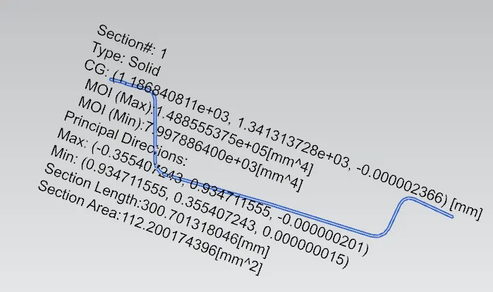
Moment of inertia(Imax) = 1.488555375 x 10^5 (mm^4)
Moment of inertia(Imin) = 7.997886400 x 10^3 (mm^4)
Section modulus S = MOI / distance between the neutral axis and extreme end of the object.
i.e S = I/Y
For (MOI)max = Imax/Y
= (1.488555375 x 10^5) / 58.5
Smax = 2544.53 mm^3
For (MOI)min = Imin/Y
= (17.997886400 x 10^3) / 58.5
Smin = 307.65 mm^3
REAR ROOF RAIL
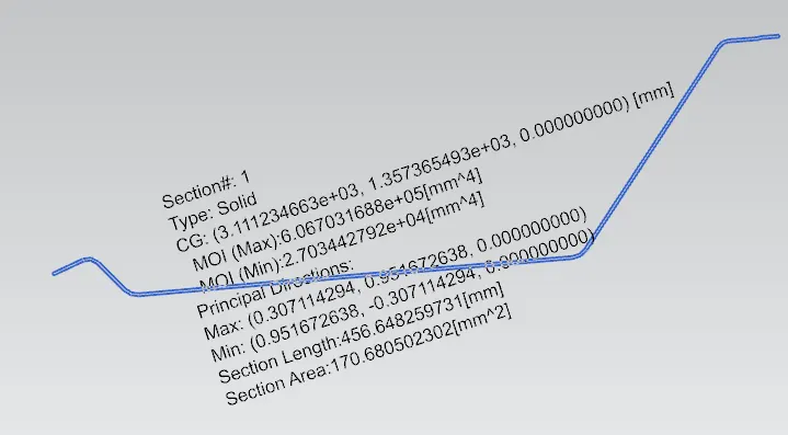
Moment of inertia(Imax) = 6.067031688 x 10^5 (mm^4)
Moment of inertia(Imin) = 2.703442792 x 10^4 (mm^4)
Section modulus S = MOI / distance between the neutral axis and extreme end of the object.
i.e S = I/Y
For (MOI)max = Imax/Y
= (6.067031688 x 10^5) / 101.1
Smax = 6001.02 mm^3
For (MOI)min = Imin/Y
= (12.703442792 x 10^4) / 101.1
Smin = 1256.52 mm^3
- DRAFT ANALYSIS
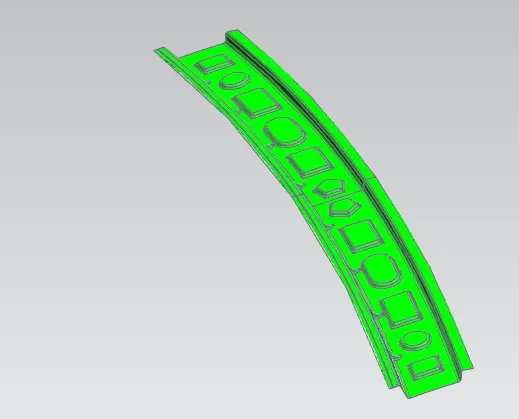
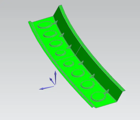
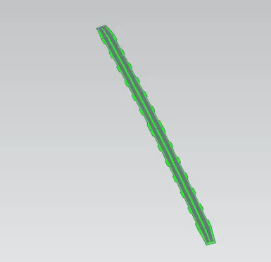
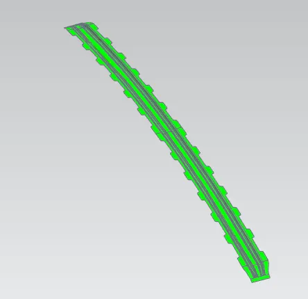
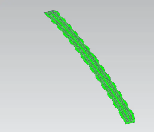
The Draft Analysis command enables you to detect if the part you drafted will be easily removed. This type of analysis is performed based on color ranges identifying zones on the analyzed element where the deviation from the draft direction at any point, corresponds to specified values.
Root outer panel
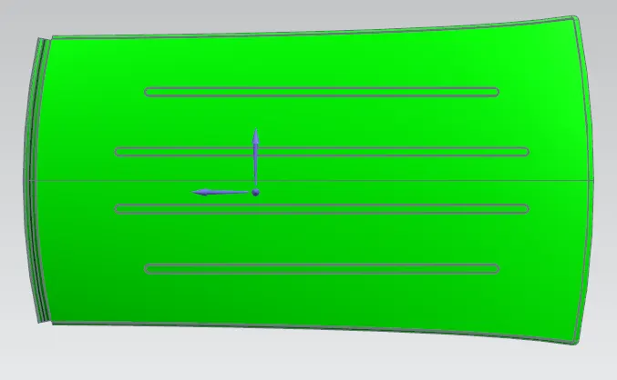
Front roof rail
Rear roof rail
Bow roof1
Bow roof2
Center roof rail
CONCLUSION
- The design of front roof rail, rear roof rail, bow roofs, and center roof rails are successfully designed as per the given master sketch and dimensions.
- All reinforcements are designed according to input data provided by styling team and also the heat distortion and snow load criteria are with in the given conditions.
- We found that some values of Qr are not meeting the given conditions, for this we created embosses on the top of roof to improve the strength of the roof.
- Section modulous and draft analysis are carried out to check the feasibility of the manufacturing and found OK.